In March of 1927, in B. Franklin Mahoney’s small San Diego manufacturing plant, the construction of Charles Lindbergh’s Spirit of St. Louis began. Less than three months later, this modest little monoplane touched off a burst of aeronautical enthusiasm that would serve as a catalyst for the nascent American aircraft industry. Just when the first bits of wood and metal that would become the Spirit of St. Louis were being fashioned into shape, another project of significance to the history of American aeronautics commenced. This was the dismantling of the experiment station of the U. S. Air Service’s Engineering Division at McCook Field, Dayton, Ohio.
|
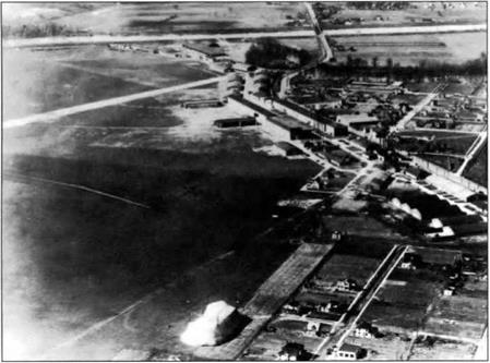
Figure 1. Aerial view of the Engineering Division’s installation at McCook Field, Dayton, Ohio.
|
45
P Galison and A. Roland (eds.), Atmospheric Flight in the Twentieth Century, 45-66 © 2000 Kluwer Academic Publishers.
For ten years, this bustling 254-acre installation, was the site of an incredible breadth of aeronautical research and development activity. By the mid-1920s, however, the Engineering Division, nestled within the confines of the Great Miami River and the city of Dayton, literally had outgrown its home, McCook Field. In the spring of 1927, the 69 haphazardly constructed wooden buildings that housed the installation were torn down, and the tons of test rigs, machinery, and personal equipment were moved to Wright Field, the Engineering Division’s new, much larger site several miles down the road.1 The move to Wright Field would be followed by further expansion in the 1930s with the addition of Patterson Field. In 1948, these two main sites were formally combined to create the present Wright- Patterson Air Force Base, one of the world’s premier aerospace R&D centers.
Although an event hardly equal to Lindbergh’s epic transatlantic flight, historically, the shut down of McCook Field offers a useful vantage point to reflect upon the beginnings of American aerospace research and development. In the 1920s, before American aeronautical R&D matured in the form of places such as Wright-Patterson AFB, basic research philosophies, and the roles of the government, the military, and private industry in the development of the new technology of flight, were being formulated and fleshed out. Just how research and manufacture of military aeronautical technology would be organized, how aviation was to become a part of overall national defense, and how R&D conducted for the military would influence and be incorporated into civil aviation, were still all wide open questions. The resolution of these issues, along with the passage of several key pieces of regulatory legislation,2 were the foundation of the dramatic expansion of American aviation after 1930. Lindbergh’s flight was a catalyst for this development, a spark of enthusiasm. But the organization of manufacture and the refinement of engineering knowledge and techniques in this period were the substantive underpinnings of future U. S. leadership in aerospace.
The ten-year history of McCook Field is a rich vehicle for studying these origins of aerospace research and manufacture in the United States. The facility was central to the emergence of a body of aeronautical engineering practices that brought aircraft design out of dimly lit hangars and into the drafting rooms of budding aircraft manufacturers. Further, McCook served as a crossroads for three of the primary players in the creation of a thriving American aircraft industry – the government, the military, and private aircraft firms.
A useful way to characterize this period is the “adolescence” of American aerospace development. The decade after the Wrights’ invention of the basic technology in 1903 was dominated by bringing aircraft performance and reliability to a reasonable level of practicality. One might think of this era as the “gestation,” or “birth,” of aeronautics. To continue the metaphor, it can be argued that by the 1930s aviation and aeronautical research and development had reached early “maturity.” The extensive and pervasive aerospace research establishment, and its interconnections to industry and government, of the later twentieth century was in place in recognizable form by this time. It was in the years separating these two stages of development, the late teens and 1920s, that the transition from rudimentary flight technology supported by minimal resources to sophisticated R&D carried out by professional engineers and technicians in well-organized institutional settings took place. In this period of “adolescence,” aeronautical research found its organizational structure and direction, aeronautical engineering practices and knowledge grew and became more formalized, and the relationship of this emerging research enterprise and manufacturing was established. McCook Field was a nexus of this process. In the modest hangars and shops of the Engineering Division, not only were the core problems of aircraft design and performance pursued, but also energetically engaged was research on the wide range of related equipment and technologies that today are intimately associated with the field of aeronautics. The catch-all connotation of “aerospace technology” that undergirds our modem use of the term took shape in the 1920s at facilities such as McCook. Moreover, the administrators and engineers at McCook were at the center of the debate over how the fruits of this research should be incorporated into the burgeoning American aircraft industry and into national defense policy. In large measure, the structure of the United States’ aerospace establishment that matured after World War II came of age in this period, when aerospace was in adolescence.
There were of course several other key centers of early aeronautical R&D beyond McCook Field, most notably the National Advisory Committee for Aeronautics and the Naval Aircraft Factory. Both of these government agencies had significant resources at their command and made important contributions to aeronautics. My focus on McCook is not to suggest that these other organizations were peripheral to the broader theme of the origins of modem flight research. They were not. McCook does, however, as a case study, present a somewhat more illuminating picture than the other facilities because of the broader range of activities conducted there. Moreover, NACA and the Naval Aircraft Factory are the subjects of several scholarly and popular books. The story of McCook Field remains largely untreated by professional historians. If nothing else, this presentation should demonstrate the need for additional study of this important installation.3
As is often the case, a temporary measure taken in time of emergency ends up serving a permanent function after the crisis has subsided. This was true of the Engineering Division at McCook Field. Established as a stopgap facility to meet some very specific needs when the United States entered World War I, McCook remained in existence after the war and developed into an important research center for the still young technology of flight. (“McCook Field” quickly became the unofficial shorthand reference for the facility and was used interchangeably with “Engineering Division.”)
Heavier-than-air aviation formally entered the American military in 1907 with the creation of an aeronautical division within the U. S. Army Signal Corps.4 In 1909, the Army purchased its first airplane from Wilbur and Orville Wright for $30,000.5 With the acquisition of several others, the Signal Corps began training pilots and exploring the military potential of aircraft in the early teens. Even with these initial steps, however, there was little significant American military aeronautical activity before World War I.
A seemingly ubiquitous feature of human conflict throughout history is the entrepreneur who, when others are weighing the geopolitical and military factors of an impending war, see a golden opportunity for financial gain. The First World War is a most conspicuous example. In that war, there is likely no better case of extreme private profit at the expense of the government war effort than the activities of the Aircraft Production Board. In the midst of this financial legerdemain, McCook Field was bom.
After the United States declared its involvement in the war and the Aircraft Production Board was set up, the dominance of Army aviation quickly settled in Dayton, Ohio. Howard E. Coffin, a leading industrialist in the automobile engineering field, was put in charge of the APB. Coffin appointed to the board another powerful leader of the Dayton-Detroit industrial circle, Edward A. Deeds, general manager of the National Cash Register Company.6 Deeds was given an officer’s commission and headed up the Equipment Division of the aviation section of the Signal Corps. This gave him near complete control over aircraft production.
Earlier, in 1911, Deeds had begun to organize his industrial interests with the formation of the Dayton Engineering Laboratories Company (DELCO). His partners included Charles Kettering and H. E. Talbott. In 1916, when European war clouds were drifting toward the United States, Deeds and his DELCO partners, along with Orville Wright, formed the Dayton-Wright Airplane Company in anticipation of large wartime contracts.7
By the eve of the American declaration of war, Coffin and Deeds had the framework for a government supported aircraft industry in place, organized around their own automotive, engineering, and financial interests and connections. Carefully arranged holding companies obfuscated any obvious conflict of interest, while Coffin and Deeds administered government aircraft contracts with one hand and received the profits from them with the other.8 Having orchestrated this grand profit-making venture in the name of making the world safe for democracy, Coffin crowned the achievement with a rather pretentious comment in June of 1917:
We should not hesitate to sacrifice any number of millions for the sake of the more precious lives which the expenditures of this money will save.9
An easy statement of conviction to make coming from someone who stood to reap a significant portion of those “any number of millions.”
Ambitious military plans for thousands of U. S.-built aircraft10 quickly pointed to the need for a centralized facility to carry out the design and testing of new aircraft, the reconfiguration of European airframes to accept American powerplants, and to perform the developmental work on the much lauded Liberty engine project. The Aircraft Production Board was concerned that a “lack of central engineering facilities” was delaying production and requested that “immediate steps be taken to provide proper facilities.”11 Here again, Edward Deeds was at the center of things, succeeding at maneuvering government money into his own pocket.
The engineers of the Equipment Division suggested locating a temporary experiment and design station at South Field, just outside Dayton. This field, not so coincidently, was owned by Deeds and used by the Dayton-Wright Airplane
Company. Charles Kettering and H. E. Talbott, Deeds’ partners, objected to the idea, arguing that they needed South Field for their own experimental work for the government contracts already awarded to Dayton-Wright. Kettering and Talbott suggested a nearby alternative, North Field.12
Found acceptable by the Army, this site was also owned by Deeds, along with Kettering. Deeds conveyed his personal interest in the property to Kettering, who in turn signed the field over to the Dayton Metal Products Company, a firm founded by Deeds, Kettering, and Talbott in 1915. In terms arranged by Deeds, Dayton Metal Products leased North Field to the Army beginning on October 4, 1917, at an initial rate of $12,000 per year.13
As the lease was being negotiated, the Aircraft Production Board adopted a resolution renaming the site McCook Field in honor of the “Fighting McCooks,” a family that had distinguished itself during the Civil War and had owned the land for a long period prior to its acquisition by Deeds.14
Thus, the creation of McCook Field took place amidst a series of complex financial and bureaucratic dealings against a backdrop of world war. The basic result was the centralization of American aeronautical research and production, both financially and physically, in the hands of this tightly integrated, Dayton – based industrial group. During the war, the Aircraft Production Board and the people who controlled it would direct American aeronautical research and production. The issue of the individual roles of government and private industry in aviation, however, would re-emerge and continue to be addressed in the postwar decade. The engineering station at McCook Field would be a principal arena for this process.
The experimental facility at McCook was almost as well known for its numerous reorganizations as it was for the research it conducted. Shortly after the American declaration of war, the meager airplane and engine design sections that comprised the engineering department of the Signal Corps’ aviation section were consolidated and expanded into the Airplane Engineering Department. Headed by Captain Virginius E. Clark, this department was under the Signal Corps’ Equipment Division that Edward Deeds administered.15 The aviation experiment station at McCook would be continually restructured and compartmentalized throughout the war. It officially became known as the Engineering Division in March 1919 when the entire Air Service was totally reorganized.16
The Army’s aeronautical engineering activity in Dayton began even before the facilities at McCook were ready. With wartime emergency at hand, Clark and his people started work in temporary quarters set up in Dayton office buildings. By December 4, 1917, construction at McCook had progressed to the point where Clark and his team could take up residency. Always intended to be a temporary facility, the buildings were simple wooden structures with a minimum of conveniences. They were cold and drafty in the winter and hot and vermin-infested in the summer. A variety of flies, insects, and rodents were constant research companions.17 Upkeep and heating were terribly expensive and the slapdash wooden construction was an ever-present fire hazard.18
In spite of these less than ideal working conditions, the station immersed itself in a massive wartime aeronautical development program. It was quickly realized that if the United States’ aviation effort was to have any impact in Europe at all, it would have to limit attempts at original designs and concentrate on re-working existing European aircraft to suit American engines and production techniques. This scheme, however, proved to be nearly as involved as starting from scratch because of the difference in approach of American mass production to that of Europe.
During World War I, European manufacturing techniques still involved a good deal of hand crafting. Engine cylinders, for example, were largely hand-fitted, a handicap that became very evident when the need to replace individual cylinders arose at the battle front. Although the production of European airframes was becoming increasingly standardized, each airplane was still built by a single team from start to finish.
American mass production, by contrast, had by this time largely moved away from such hand crafting in many industries. During the nineteenth century, mass production of articles with interchangeable parts became increasingly common in American manufacture. Evolving within industries such as firearms, sewing machines, and bicycles, production with truly interchangeable parts came to fruition with Henry Ford’s automobile assembly line early in the twentieth century.19
By 1917, major American automobile manufacturers were characterized by efficient, genuine mass production. When the U. S. entered World War I, it was hoped that a vast air fleet could be produced in short order by adapting American production techniques and facilities already in place for automobiles to aircraft. The
|

Figure 2. The main design and drafting room at McCook.
|
|
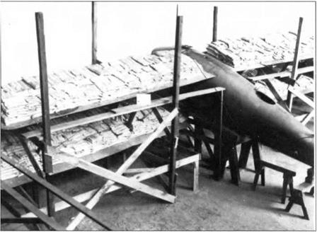
Figure 3. A biplane being load tested in the Static Testing Laboratory at McCook.
|
most notable example of this auto-aero production crosslink was the highly touted Liberty engine project.20
If U. S. assembly line techniques were to be effectively employed, however, accurate, detailed drawings of every component of a particular airplane or engine were required. Consequently, when the engineers at McCook began re-working European designs, huge numbers of production drawings had to be prepared. To produce the American version of the British De Havilland DH-9, for instance, approximately 3000 separate drawings were made. This was exclusive of the engine, machine guns, instruments, and other equipment apart from the airframe. Another principle re-design project, the British Bristol Fighter F-2B, yielded 2500 production drawings for all the parts and assemblies.21 As a result, the time saved reworking European aircraft to take advantage of American assembly line techniques, rather than creating original designs, was minimal.
In addition to adopting assembly line type production, the McCook engineers developed a number of other aids that helped transcend cut-and-try style manufacture. For example, a systematic method of stress analysis using sand bags to determine where and how structures should be reinforced was devised. Also, a fairly sophisticated wind tunnel was constructed enabling the use of models to determine appropriate wing and tail configurations before building the full-size aircraft. (This was the first of two tunnels. The more famous “Five-Foot Wind Tunnel” would be built in 1922.) These and other design tools began to transform the staff at McCook from mere airplane builders into aeronautical engineers.
In the end, even with all the effort to gear up for mass production, American industry produced comparatively few aircraft,22 and did so at a very high cost to the government. But this was due more to corruption in the administration of aircraft production than to the techniques employed.23 Still, the efforts of the engineers at McCook Field were not fruitless. They contributed to bringing aviation into the professional discipline of engineering that had been developing in other fields since the late nineteenth century. Although the American aeronautical effort had little impact in Europe, the approach adopted at McCook was an important long term contribution to the field of aeronautical engineering and aircraft production. It was, in the United States at least, the bridge over which homespun flying machines stepped into the realm of truly engineered aircraft.
Even though it was only intended to serve as a temporary clearinghouse for the wartime aeronautical build up, McCook Field did not close down after hostilities ended. In fact, it was in the postwar phase of its existence that the station made its most notable contributions. Colonel Thurman Bane took over command from Virginius Clark in January 1919, and under his leadership McCook expanded into an extremely wide-ranging research and development center. During the war, the facility was primarily involved with aircraft design and production problems. After, the Engineering Division continued to design aircraft and engines, but its most significant achievements were in the development of related equipment, materials, testing rigs, and production techniques that enhanced the performance and versatility of aircraft and aided in their manufacture. Virtually none of the thirty-odd airplanes designed by McCook engineers during the 1920s were particularly remarkable machines. (Except, perhaps, for their nearly uniform ugliness.) But in terms of related equipment, materials, and refinement of aeronautical engineering knowledge, the R&D at McCook was cutting edge. The list of McCook firsts is lengthy. The depth and variety of projects tackled by the Engineering Division made it one of the richest sources of engineering research in its day.
Among the most significant contributions made by the Engineering Division were those in the field of aero propulsion. The Liberty engine was a principal project during the war and after. Although fraught with problems early in its development, in its final form the Liberty was one of the best powerplants of the period. It was clearly the single most important technological contribution of the United States’ aeronautical effort during World War I. In addition, it powered the Army’s four Douglas World Cruisers that made the first successful around-the-world flight in 1924.
The Liberty engine was only part of the story. As early as 1921, the Engineering Division had built a very successful 700 hp engine known as the Model W, and was at work on a 1000 hp version.24 These and other engines were developed in what was recognized as the finest propulsion testing laboratory in the country. It featured several very large and sophisticated engine dynamometers. The McCook engineers also built an impressive portable dynamometer mounted on a truck bed. Engine and test bed were driven up mountainsides to simulate high altitude running conditions.25
The Engineering Division had a particularly strong reputation for its propeller research. Some of the most impressive test rigs anywhere operated at McCook. In fact, one of the earliest, first set up in 1918, is still in use at Wright-Paterson AFB. High speed whirling tests were done to determine maximum safe rotation speeds, and water spray tests were conducted to investigate the effects of flying in rain storms. Extensive experimentation with all sorts of woods, adhesives, and construction techniques was also performed. In addition, some of the earliest work with metal and variable pitch propellers was carried out at McCook. Propulsion research also included work on superchargers, fuel systems, carburetors, ignition systems, and cooling systems. Experimental work with ethylene-glycol as a high temperature coolant that allowed for the reduction in size of bulky radiators was another significant McCook contribution in this field.26
Aerodynamic and structural testing were other key aspects of the Engineering Division’s research program. Alexander Klemin headed what was called the Aeronautical Research Department. Klemin had been the first student in Jerome Hunsaker’s newly established aeronautical engineering course at MIT. So successful had Klemin been that he succeeded Hunsaker as head of the aeronautics program at MIT. When the United States entered the war, he joined the Army and went to McCook.27
|
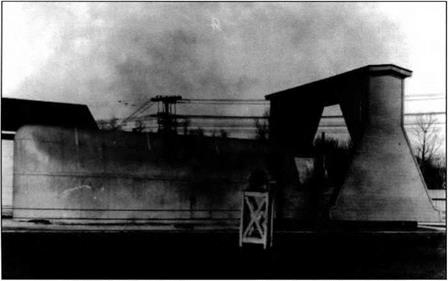
Figure 4. The propulsion research at McCook was particularly strong. One of these early propeller test rigs is still in use today at Wright-Patterson Air Force Base.
|
|
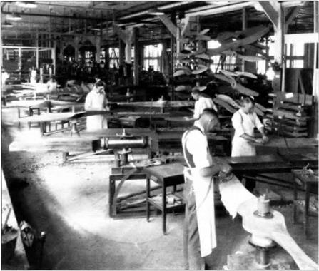
Figure 5. The propeller shop hand-crafted propellers of all varieties for research and flight test purposes.
|
Klemin’s work during and after the war centered around bringing theory and practice together in the McCook hangars. The Engineering Division’s wind tunnel work was a prime example. The tunnel built during World War I was superseded by a much larger tunnel built in 1922. Known as the “five foot tunnel,” it was a beautiful creation built up of lathe-turned cedar rings. The McCook tunnel was 96 feet in length and had a maximum smooth airflow diameter of five feet, hence the name.28 Although the National Advisory Committee for Aeronautics’ variable density tunnel completed the following year was the real breakthrough instrument in the field,29 the McCook tunnel provided important data and helped standardize the use of such devices for design purposes.
Among the activities of the Aeronautical Research Department were the famous sand loading tests. Under Klemin’s direction this method of structural analysis was refined to a high degree. Although the NACA became the American leader in aerodynamic testing with its variable density tunnel, McCook led the way in structural analysis.30
Materials research was another area in which the Engineering Division was heavily involved. Great strides were made in their work with aluminum and magnesium alloys. These products found important applications in engines, airframes, propellers, airship structure, and armament. In 1921, the Division was at work on this country’s first all duraluminum airplane.31 Materials research also included developmental work on adhesives and paints, fuels and lubricants, and fabrics, tested for strength and durability for applications in both aircraft coverings and parachutes.32
One of the most often-cited achievements at McCook was the perfecting of the free-fall parachute by Major Edward L. Hoffman. First used at the inception of human flight by late-eighteenth century balloonists, the parachute remained a somewhat dormant technology until after World War I. Prior to Hoffman’s work, bulk and weight concerns overrode the obvious life-saving potential of the device. Hoffman experimented with materials, various shapes and sizes for the canopy, the length of the shroud lines, the harness, vents for controlling the descent, all with an eye toward increased efficiency and reliability. His systematic approach was characteristic of the emerging McCook pattern.
|
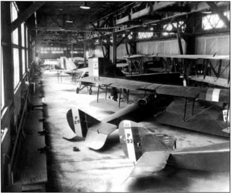
Figure 6. The Flight Test hangar at McCook, showing the range of aircraft types being evaluated by the Engineering Division.
|
|
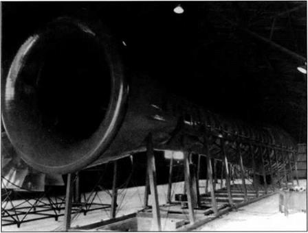
Figure 7. The Five-Foot Wind Tunnel, built in 1922, bad a maximum airflow speed of 270 mph.
|
|
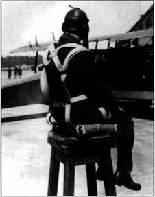 Figure 8. The “pack-on-lhc-aviator” parachute design that was perfected at MrC innlr
After numerous tests with dummies, Leslie Irvin made the first human test of Hoffman’s perfected chute on April 28, 1919. Designated as the Type A, this was a modem-style “pack-on-the-aviator” design with a ripcord that could be manually activated during free fall. Though completely successful, parachutes did not become mandatory equipment for U. S. Army airmen until 1923, a few months after Lt. Harold Harris was saved by one after his Loening monoplane broke apart in the air on October 20, 1922. Harris’ exploit was the first instance of an emergency use of a free-fall parachute by a U. S. Army pilot.33
Aerial photography was another of the related fields that was significantly advanced during the McCook years. The Air Service had initiated a sizeable photo reconnaissance program during the war. Work in this field continued during the 1920s, and it became one of the most noted contributions of the Engineering Division. Albert Stevens and George Goddard were the central figures of aerial photography and mapping at McCook. Goddard made the first night aerial photographs and developed techniques for processing film on board the aircraft. In 1923, Stevens, with pilot Lt. John Macready, made the first large-scale photographic survey of the United States from the air. Stevens had particular success with his work in high altitude photography. By 1924, Air Service photographers were producing extremely detailed, undistorted images from altitudes above 30,000 feet, covering 20 square miles of territory.34
In addition to the obvious military value of aerial photography, this capability was also being employed in fields such as soil erosion control, tax assessment, contour mapping, forest conservation, and harbor improvements. The fruits of the research at McCook often extended beyond purely aeronautical applications.
The demands of the aerial photography work were also an impetus to other areas of aeronautical research. The need to carry cameras higher and higher stimulated propulsion technology, particularly superchargers. Flight clothing and breathing devices were similarly influenced. Extreme cold and thin air at high altitudes resulted in the development of electrically heated flight suits, non-frosting goggles, and oxygen equipment.35
Several important contributions in the fields of navigation and radio communication that would help spur civil air transport were developed at McCook. The first night airways system in the United States was established between Dayton and Columbus, Ohio. This route was used to develop navigation and landing lights, boundary and obstacle lights, and airport illumination systems. Experimentation with radio beacons and improved wireless telephony were also part of the program. These innovations proved especially valuable when the Department of Commerce inaugurated night airmail service. Advances in the field of aircraft instrumentation, included improvements in altimeters, airspeed indicators, venturi tubes, engine tachometers, inclinometers, tum-and-bank indicators, and the earth induction compass, just to name a few. Refinement of meteorological data collection also made great strides at McCook. The development of such equipment was essential for the creation of a safe, reliable, efficient, and profitable, commercial air transport industry.36
|
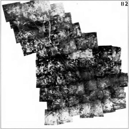
Figure 9. An example of the mapping produced by the aerial mapping photography program conducted by the Engineering Division at McCook Field.
|
Another significant economic application of aeronautics that saw development at McCook was crop dusting. The advantages of releasing insecticide over wide areas by air compared to hand spraying on the ground were obvious. In the summer of 1921, when a serious outbreak of catalpa sphinx caterpillars occurred in a valuable catalpa grove near Troy, Ohio, the opportunity to demonstrate the effectiveness of aerial spraying presented itself. A dusting hopper designed by E. Dormoy was fitted to a Curtiss JN-6. Lt. Macready flew the airplane over the affected area at an altitude of about 30 feet as he released the insecticide. He accomplished in a few minutes what normally would have taken days.37
Of course, McCook Field was a military installation, and a good deal of their research focused on improving and expanding the uses of aircraft for war. Perhaps the most significant long term contribution in this area made by the Engineering Division was their work with the heavy bomber. In the early twenties, General William “Billy” Mitchell, assistant chief of the Air Service, began to vociferously promote aerial bombardment as a pivotal instrument of war. The Martin Bomber was the Army’s standard bombing aircraft at the time. The Engineering Division worked with the Glenn L. Martin Company to re-design the aircraft, but were unable to meet General Mitchell’s requirements for a long range, heavily loaded bomber.
In 1923, the Air Service bought a bomber designed by an English engineer named Walter Barling. Spanning 120 feet and powered by six Liberty engines, the Barling Bomber was the largest airplane yet built in America. So big and heavy was the craft that it could not operate from the confined McCook airfield. Consequently, the Engineering Division had it transported by rail to the nearby Fairfield Air Depot to conduct flying tests. First flown by Lt. Harold Harris in August of 1923, the Barling Bomber proved largely unsuccessful. It was a heavy, ungainly craft that never lived up to expectations. Nevertheless, it in part influenced the Air Service, in terms of both technology and doctrine, toward strategic bombing as a central element of the application of air power.38
Complementary to the development of military aircraft was, of course, armament. McCook engineers turned out a continuous stream of new types of gun mounts, bomb racks, aerial torpedoes, machine gun synchronization devices, bomb sights, and armament handling equipment. Even experiments with bullet proof glass were conducted. The advances in metallurgy that were revolutionizing airframe and engine construction were also being employed in the development of lightweight aircraft weaponry.39
Another distinct avenue of aeronautical research that saw at least limited development at McCook was vertical flight. George de Bothezat, a Russian emigre who worked on the famous World War I Ilya Muromets bomber, designed a workable helicopter for the U. S. Army in the early 1920s. Built in total secrecy, the complex maze of steel tubing and rotor blades was ready for testing on December 18,1922. In its first public demonstration the craft stayed aloft for one minute and 42 seconds and reached a maximum altitude of eight feet. Flight testing continued during 1923. On one occasion it carried four people into the air. Although it met with some success, de Bothezat’s helicopter did not live up to its initial expectations and the project was eventually abandoned.40 Still, the vertical flight research, like the heavy bomber, demonstrates McCook’s pioneering role in numerous areas of long range importance.
Equally important as conducting research is, of course, dissemination of the results. Here again the Engineering Division’s efforts are noteworthy. During the war, the McCook Field Aeronautical Reference Library was created to serve as a clearinghouse for all pertinent aeronautical engineering literature and a repository for original research conducted at the station. By war’s end, the library contained approximately 5000 domestic and foreign technical reports, over 900 reference works, and had subscriptions to 42 aeronautical and technical periodicals. All of the material was cataloged, cross-indexed, and made available to any organization involved in aeronautical engineering. During the war, an in-house periodical called the Bulletin of the Experimental Department, Airplane Engineering Division was published. After 1918, at the urging of the National Advisory Committee for Aeronautics, the Division increased distribution of the journal to over 3000 engineering societies, libraries, schools, and technical institutes. Through these instruments, the research of the Engineering Division was documented and disseminated. McCook proved to be an invaluable information resource to both the military and private manufacturing firms throughout the period.41
In addition, in 1919, the Air Service set up an engineering school at McCook. Carefully selected officers were trained in the rudiments of aircraft design, propulsion theory, and other related technical areas. This school still operates today as the Air Force Institute of Technology.42
The Engineering Division’s role as a technical, professional information resource was complemented by its efforts to keep aviation in the public eye. During the 1920s, Dayton became almost as famous for the aerial exploits of the McCook flying officers as it was for being the home of Wilbur and Orville Wright. Speed and altitude records were being set on a regular basis. These flights were in part integral to the research, but they had a public relations component as well. With the postwar wind down of government contracts, private investment had to be cultivated. The Engineering Division saw a thriving private aircraft industry that could be tapped in time of war as essential to national security. The publicity garnered from recordsetting flights was in part intended to draw support for a domestic industry.
There were hundreds of celebrated flying achievements that originated with the Engineering Division, but two events in particular brought significant notoriety to McCook Field and aviation. In 1923, McCook test pilots Lt. Oakley G. Kelly and Lt. John A. Macready made the first non-stop coast-to-coast flight across the United States. Their Fokker T-2 aircraft was specially prepared for the flight by the Engineering Division. Kelly and Macready departed from Roosevelt Field, Long Island, on May 2, and completed a successful flight with a landing in San Diego, California, in just under 27 hours.43
The following year, the Air Service decided to attempt an around-the-world flight. Again, preparations and prototype testing were done at McCook. Four Douglas-built aircraft were readied and on April 6, 1924, the group took off from Seattle, Washington. Only two of the airplanes completed the entire trip, but it was a technological and logistical triumph nonetheless. The achievement received international acclaim and was one the most notable flights of the decade.44
This cursory discussion of McCook Field research and development from propulsion to public relations is intended to be merely suggestive of the rich and diversified program administered by the Engineering Division of the U. S. Air Service. McCook is something of an historical Pandora’s box. Once looked into, the list of technological project areas is almost limitless. One program dovetails into the next, and all were carried out with thoroughness and sophistication.
One obvious conclusion that can be drawn from this brief overview is the powerful place McCook Field holds in the maturation of professional, high-level
|
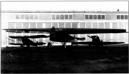
Figure 10. Among the more famous aircraft prepared at McCook Field were the Fokker T-2 (center), which made the first non-stop U. S. transcontinental flight in 1923, and the Verville – Sperry Racer (right), which featured retracting landing gear.
|
aeronautical engineering in the United States, and its influence on the embryonic American aircraft industry. Beginning with the World War I experience, aircraft were now studied and developed in terms of their various components. Systematic testing and design had replaced cut-and-try. The organized approach to problems that characterized the Engineering Division’s research program became a model for similar facilities. Many who would later become influential figures in the American aircraft industry were “graduates” of McCook. They took with them the experience and techniques learned at the small Dayton experiment station and helped create an industry that dominated World War II and became essential thereafter. While the Engineering Division was by no means the singular source of aeronautical information and skill in this period, a review of their research activity and style clearly illustrate their extensive contributions to aeronautical engineering knowledge, as well as the formation of the professional discipline. In these ways aeronautics was transformed from simply a new technology into a new field, a new arena of professional, economic, and political significance.
The crosslink between McCook and private industry involved more than the transfer of technical data and experienced personnel. There was also a philosophical component at work of great importance with respect to how future government sponsored research would be conducted. Military engineers and private aircraft manufacturers agreed that a well developed domestic industry was in the best interest of all concerned. Yet, each had very different ideas regarding how it should be organized and what would be their individual roles.
McCook Field had, of course, been intimately tied to private industry since its creation. Its initial purpose was to serve as a clearinghouse for America’s hastily gathered aeronautical production resources upon the United States’ entry into World War I. Although the installation had a military commander, it was under the administration of industrial leader Edward Deeds.
During the war, when contracts were sizeable and forthcoming, budding aircraft manufacturers had few problems with the Army’s involvement in design and production. By 1919, however, when heavy government subsidy dried up and contracts were canceled, the interests of the Engineering Division and private manufacturers began to diverge. Throughout the twenties, civilian industry leaders and the military engineers at McCook exchanged accusations concerning responsibilities and prerogatives.
Even though government contracts were severely curtailed after the war, the military was still the primary customer for most private manufacturers. Keenly aware of this, the Army attempted to follow a course that would aid these still relatively small, hard pressed private firms, as well as facilitate their needs for aircraft and equipment. They continually reaffirmed their position that a thriving private industry that could be quickly enlisted in time of national emergency was an essential component of national defense. In a 1924 message to Congress, President Coolidge commented that “the airplane industry in this country at the present time is dependent almost entirely upon Government business. To strengthen this industry is to strengthen our National Defense.”45 Such statements reflected the “pump-priming” attitude toward the aircraft industry that was typical throughout the government, not only among the military. By providing the necessary funds to get private manufacturers on sound footing, government officials felt they were at once bolstering the economy as well as meeting their mandate of providing national security.46
These sentiments were backed up with action. For example, in 1919, Colonel Bane, head of the Engineering Division, recommended an order be placed with the Glenn L. Martin Company for fifty bombers. The Army needed the airplanes and such an order would at least cover the costs of tooling up and expanding the Martin factory. In addition to supplying aircraft, it was believed that this type of patronage would help create a “satisfactory nucleus,…, capable of rapid expansion to meet the Government’s needs in an emergency.”47 On the surface, it seemed like a beneficial approach all the way around.
This philosophy, however, met with resistance from the civilian industry. They liked the idea of government contracts, but they felt the Army was playing too large a role in matters of design and the direction the technology should go. They were concerned private manufacturers would become slaves to restrictive military design concepts as a result of their financial dependency on government contracts. By centralizing the design function of aircraft production within the military, it would stifle originality and leave many talented designers idle.48 Moreover, they believed that in a system where private firms merely built aircraft to predetermined Army specifications, they would be in a vulnerable position. They feared the Army would take the credit for successful designs and that they would be blamed for the failures.49 The civilian industry hoped to gain government subsidy, but wanted to do their own developmental work and then provide the Army with what they believed would best serve the nation’s military needs.
The Engineering Division’s response to this philosophical divergence was twofold. First, they asserted that Army engineers were in the best position to assess the Air Service’s needs and having them do the design work was the most efficient way to build up American air defenses. They claimed civilian designers sacrificed ease of production and maintenance for superior flight performance. Key to a military aircraft construction program, it was argued, were designs that were simple enough to mass produce and then maintain in the field by minimally-trained mechanics. When other performance parameters are the primary goal, complexity and expense often creep into the final product. Although performance factors such as speed and maneuverability were certainly important to the Army, utility and practicality remained higher priorities. This difference in outlook was among the principal reasons why the Engineering Division did not want to give up their design and development prerogatives.50
The other divisive issue was the conduct of basic research. The Engineering Division stressed the crucial nature of this type work with a new technology such as aeronautics. They were concerned that private industry, particularly in light of its troubled financial situation, would be reluctant to undertake fundamental research due to its frequent indefinite results and prohibitive costs. They would, understandably, focus on projects that promised fairly immediate financial return. Leon Cammem, a prominent New York engineer, skillfully summarized the Army’s position in an article that appeared in The Journal of the American Society of Mechanical Engineers. He concluded that “it is obvious that if aeronautics is to be developed in this country there must be some place where investigations into matters pertaining to this new art can be carried on without any regard to immediate commercial returns.” He suggested that place should be McCook Field.51
Throughout the 1920s, the civilian industry assailed the government, and the Engineering Division in particular, for attempting to undercut what they saw as their role in the development of this new field of technological endeavor. Although the military always had the upper hand in the McCook era, industry leaders managed to keep the issues on the table. Pressures on the industry eased somewhat in the 1930s because a sizeable commercial aviation market was emerging and gave private manufacturers a greater degree of financial autonomy. Yet, battles over research and decision making prerogatives continued to arise whenever government contracts were involved. Although the dollar amounts are higher and the technological and ethical questions more complex, many of the organizational issues of modern, multi-billion-dollar aerospace R&D are not new. The historical point of significance is that it was in the 1920s that such organizational issues were first raised and began to be sorted out. Again, the notion of a field in adolescence, finding its way, establishing its structural patterns for the long term clearly presents itself A look at the formative years of the American aircraft industry and government-sponsored aeronautical research shows that these organizational debates were an early feature of aviation in the United States, and that the Engineering Division at McCook Field was an intimate player in this history. Given this, and McCook’s countless contributions to aeronautical engineering, it is perhaps only a slight overstatement to suggest that the beginnings of our current-day aerospace research establishment lie in a small piece of Ohio acreage just west of Interstate 75 where today, among other things, the McCook Bowling Alley now resides.


 Figure 8. The “pack-on-lhc-aviator” parachute design that was perfected at MrC innlr

