Category Archimedes

TAKE-OFF AND TRANSFER

Vandervoot Walsh, an assistant professor of architecture at Columbia wrote in 1931: “I suspect most engineers believe that the correct method of designing an airport is to let them lay the whole thing out, insuring its practicability: and then, if there is any money left, to call in an architect to spread a little trimming around on the outside of the buildings to make them look pretty.”54 Walsh felt that engineers believed that they could design an airport without an architect. The architect, suggested Walsh, did not share the same conviction about his own skills; the architect “understood” he could not design an airport without the help of an engineer.

Walsh was hardly arguing that an architect was superfluous, rather his article was a strongly-worded declaration of the architect’s rightful place in the design process. The value an architect provided was not in the “trimmings”; in fact, using an architect in this way was surely a waste of money according to Walsh. “Flying will never become generally popular until airports become more than merely practical and safe. They must affect the human emotions, establishing a mental state of ease through a feeling of comfort, safety and other emotions producing pleasure.”55

By the beginning of the 1930s, airport engineers embraced the idea that airport design should pay consideration to psychological factors. They agreed with the architects that the physical appearance of the airport help convey the image of permanence while disguising the very real discomforts and hazards of aviation. The question was to what degree and at which phase of the design process should they be incorporated. Further, there was no established mechanism for coordination between engineers and architects. As Walsh wrote, “practically no engineers have the training which architects have in the technique of keeping the planning in a very plastic condition, capable of quick changes as new and better ideas pass through the mind.”56 On the other hand, few architects understood the dynamics of airplanes and aircraft movement. Architects emphasized in their airport designs the idea of maximizing the functionality of the buildings; airport engineering design emphasized the functionality of the airplane.

It is important to keep in mind that airport design was more complicated than the design of a single facility. What becomes clear is that despite the assertions of the architect, both the architect and engineer were vitally interested in the problems of transfer. However, for the architect “transfer” was a local, small-scale phenomenon – how to get passengers between airplane and car, train, or bus. For the engineer, the problem of transfer was how to get passengers in and out of the air so that they could get from one airport to another.

There was no real resolution of competing claims for technical expertise over airport design in 1931 and 1932, just an acceptance that the amount of money being spent and the increase in passenger traffic had dictated a much more complex set of solutions to the problems of airport design. There was a consensus that airport design had to address two fundamental problems – takeoff-and-landing and transfer. As the matter of take-off and landing still was seen as the more pressing of the two problems, the engineers enjoyed the upper hand; but their visibility, if not their influence, was waning. Architects spoke more eloquently and effectively and captured public imagination. Architects proved much more adept at embedding the rhetoric of the American cultural ideals of progress and modernity in their descriptions of airport design. Again, Vandervoot Walsh provides a good (if lengthy) example:

Since we must admit that one of the grandest achievements of the human race is its newly acquired power to fly, then no airport is worthy of its existence if it does not express in its form the poetry of this great event. … There are others who say that the days of story-telling in archi­tecture are over, that all buildings have essentially become machines – cold, inhuman, efficient, doing their work with precision and speed. Let us hope, though, that the builders of airports will have a bigger vision than this, that engineers will realize that with human beings there is a spirit as well as body that must be satisfied. And that they will be willing to cooperate with architects to make these places of embarkation into the skies worthy of the great science of aviation.57

The reduced visibility of airport engineers was not really due to a lack of poetry but rather the fact that their profession was undergoing significant change. In 1931, Archibald Black expressed his concern for the “vanishing airport engineer” in a brief polemic published in The American City. Black was correct when he noted that there were fewer airport engineers but what was disappearing was the airport engineer who functioned in the same manner as the medical general practitioner – student of all the major airport systems but true expert in none. That airport engineer was about to be replaced by a new type – one more fully engaged in the technological problems of making an individual airport system function within a national system of airports and air transportation. That change was a direct consequence of the new involvement of architects in airport design.58

THE EVOLUTION OF AERODYNAMICS IN THE TWENTIETH-CENTURY:. ENGINEERING OR SCIENCE?

INTRODUCTION

The field of aerodynamics is frequently characterized as an applied science. This appellation is simplistic, and is somewhat misleading; it is not consistent with the engineering thought process so nicely described and interpreted by Vincenti.1 The intellectual understanding of aerodynamics, as well as the use of this understanding in the design of flight vehicles, has grown exponentially during the twentieth – century. How much of this growth can be called “science”? How much can be called “engineering”? How much falls into the grey area called “engineering science”? The purpose of this paper is to address these questions. Specifically, some highlights from the evolution of aerodynamics in the twentieth-century will be discussed from an historical viewpoint, and the nature of the intellectual thought processes associated with these highlights will be examined. These highlights are chosen from a much broader study of the history of aerodynamics carried out by the author.2

For the purpose of this paper, we shall make the distinction between the roles of science, engineering, and engineering science as follows.

Science: A study of the physical nature of the world and universe, where the desired end product is simply the acquisition of new knowledge for its own sake.

Engineering: The art of applying an autonomous form of knowledge for the purpose of designing and constructing an artifice to meet some recognized need.

Engineering Science: The acquisition of new knowledge for the specific purpose of qualitatively or quantitatively enhancing the process of designing and constructing an artifice.

These distinctions are basically consistent with those made by Vincenti.3

There is perhaps no better example of the blending of the disciplines of science, engineering science, and pure engineering than the evolution of modem aerodynamics. The present paper discusses this evolution in five steps: (1) the total lack of technology transfer of the basic science of fluid dynamics in the nineteenth century to the design of flying machines at that time (prior to 1891); (2) the reversal of this situation at the beginning of the twentieth century when academic science discovered the airplane, when the success of Lilienthal and the Wright brothers

241

P Galison and A. Roland (eds.), Atmospheric Flight in the Twentieth Century, 241-256 © 2000 Kluwer Academic Publishers.


proved the feasibility of the flying machine, and when academicians such as Kutta and Joukowski developed the seminal circulation theory of lift and Prandtl introduced the concept of the boundary layer, all representing the introduction of engineering science to the study of aerodynamics (1891 – 1907); (3) the era of strut and wire biplanes, exemplified by the aerodynamic investigation of Eiffel, who blended both engineering science and engineering in his lengthy wind tunnel investigations (1909 – 1921); (4) the era of the mature propeller-driven airplane, characterized by the evolution of streamlining, representing again both engineering science and engineering; (5) the era of the modem jet propelled airplane, including the revolutionary development of the swept wing (see also the companion paper in this volume, “Engineering Experiment and Engineering Theory: The Aerodynamics of Wings at Supersonic Speeds, 1946 – 1948,” by Walter Vincenti). In the final analysis, we will see that the naive “engineering versus science” alluded to in the title of this paper fails to hold up, because the evolution of aerodynamics in the twentieth century was characterized by a subtle integration of both.

A 20TH CENTURY “BRIDGE”

Part of the reconciliation between airport engineers and architects was stimulated by their mutual confidence in the utility of city planning in the design process. In a commentary on a paper presented by Donald Baker at a major meeting in 1928 of the American Society of Civil Engineers’ City Planning Division, John Nolen, one of the nation’s preeminent city planners, wrote: “As an outstanding feature of modem transportation the airport has an effect upon the city or urban community as a unit. To choose a site without consideration of all the elements of the community composition may mean that either the city may be injured by the location given over to the airport, or, in turn, the airport may not be so situated as to serve the city economically; or still worse, it may be so placed that it cannot develop business either from the city or serve as an adequate and safe stopping point on an airway for traffic from outside.”59

What Nolen and others were suggesting was a new way of understanding the specialized contributions of engineers and architects. In the minds of city planners, neither the engineering nor the architectural treatment of an airport facility

constituted the only issues guiding airport development. Good airport design, according to Nolen, necessarily incorporated “mastery not only of the physical conditions, but also a firm grasp on their financial and economic relations under appropriate statutes, laws and regulations.”60

City planners believed their endeavors to constitute a “scientific profession,” derived from a fundamentally different basis from that of engineering or architecture. John Nolen, wrote that “successful town planning cannot be the work of a narrow specialist, or of a single profession. The call is for versatility, special knowledge and cooperation. For town planning is engineering plus something; architecture plus something; or landscape architecture plus something….”61 Nolen was keenly interested in airports. He wrote several papers about city planning and airports, was an active public speaker on the subject, and most importantly was hired by several cities to design their airports. Nolen’s philosophy of city planning was that excellent results could only be achieved if social and economic factors were considered as seriously as demographic, aesthetic, and technical criteria. This produced a strikingly different outlook on airport design than existed in the aviation community. For example, when Commerce Department officials were in the midst of their crusades to persuade American cities to build airports, John Nolen stated unequivocally to a meeting of the Aeronautic Section of the Society of Automotive Engineers that the locations of the nation’s most important airports had already been determined. Simple “boosterism” was not particularly useful to Nolen’s way of thinking.62

Most city planners shared Nolen’s assessment. Airports were like bridges, connecting formerly-separated regions and like real bridges, they had the potential to alter the economic geography of the nation. The “bridge” had little value if it was not integrated with all other modes of transportation. The third part of airport design then, was identified as connecting the airport with the local systems of ground transportation.63

By the mid-1930s, engineers, architects and city planners were all engaged in the problems of airport design. Each profession viewed the technological possibilities of an airport from very different perspectives. This might have resulted in vigorous professional competition yet, instead the engineers, architects and city planners came to embrace each other (albeit warily) in a way that resulted in a synthesis of airport design concepts. There were several diverse factors contributing to this result including the full integration of radio into airport technology; the introduction of an entirely new type of aircraft, the so-called “modem” airliners; the political and economic circumstances of the 1930s that led to the Roosevelt Administration’s dramatic increase in federal investment in airports; and an abiding American fascination with aviation and its seductive promise of speed. How these factors helped bring together these three groups of professionals is perhaps best shown through a brief recounting of the development of LaGuardia Airport in New York.

ROLES OF SCIENCE AND ENGINEERING IN NINETEENTH-CENTURY AERODYNAMICS

To understand the relationship of science and engineering to aerodynamics in the twentieth-century, we need to examine briefly the completely different relationship that existed during the nineteenth-century.

The history of aerodynamics before the twentieth-century is buried in the history of the more general discipline of fluid dynamics. Consistent with the evolution of classical physics, the basic aspects of the science of fluid dynamics were reasonably well understood by 1890. Meaningful experiments in fluid dynamics started with Edme Mariotte and Christiaan Huygens, both members of the Paris Academy of Science, who independently demonstrated by 1690 the important result that the force on a body moving through a fluid varies as the square of the velocity. The relationship between pressure and velocity in a moving fluid was studied experimentally by Henri Pitot, a French civil engineer in the 1730’s. Later in the eighteenth-century, the experimental tradition in fluid dynamics was extended by John Smeaton and Benjamin Robins in England, using whirling arms as test facilities. Finally, by the end of the nineteenth-century, the basic understanding of the effects of friction on fluid flows was greatly enhanced by the experiments of Osborne Reynolds at Manchester. These are just some examples. In parallel, the rational theoretical study of fluid mechanics began with Isaac Newton’s Principia in 1687. By 1755 Leonhard Euler had developed the partial differential equations describing the flow of a frictionless fluid – the well-known “Euler Equations” which are used extensively in modern aerodynamics. The theoretical basis of fluid mechanics was further enhanced by the vortex concepts of Hermann Von Helmholtz in Germany during the mid-nineteenth-century. Finally, the partial differential equations for the flow of a fluid with friction – the more realistic case – were developed independently by the frenchman Henri Navier in 1822 and the englishman George Stokes in 1845. These equations, called the Navier-Stokes equations, are the most fundamental basis for the theoretical study of fluid dynamics. They were well-established more than 150 years ago.

Thus, by the end of the nineteenth-century, the basic principles underlying classical fluid dynamics were well established. The progress in this discipline culminated in a complete formulation and understanding of the detailed equations of motion for a viscous fluid flow (the Navier-Stokes equations), as well as the beginnings of a quantitative, experimental data base on basic fluid phenomena, including the transition from laminar to turbulent flow. In essence, fluid dynamics was in step with the rest of classical physics at the end of the nineteenth-century – a science that was perceived at that time as being well-known, somewhat mature, with nothing more to be learned. Also, it is important to note that this science was predominately developed (at least in the nineteenth-century) by scholars who were university educated, and who were mainly part of the academic community.

The transfer of this state-of-the-art in fluid dynamics to the investigation of powered flight was, on the other hand, virtually non-existent. The idea of powered flight was considered fanciful by the established scientific community – an idea that was not appropriate for serious intellectual pursuits. Even Lord Rayleigh, who came closer than any of the scientific giants of the nineteenth-century to showing interest in powered flight, contributed nothing tangible to applied aerodynamics. This situation can not be more emphatically stated than appears in the following paragraph from the Fifth Annual Report of the Aeronautical Society of Great Britain in 1870:

“Now let us consider the nature of the mud in which I have said we are stuck. The cause of our standstill, briefly stated, seems to be this: men do not consider the subject of ‘aerostation’ or ‘avia­tion’ to be a real science, but bring forward wild, impracticable, unmechanical, and unmathematical schemes, wasting the time of the Society, and causing us to be looked upon as a laughing stock by an incredulous and skeptical public.”

Clearly, there was a “technology transfer problem” in regard to the science of fluid dynamics applied to powered flight. For this reason, applied aerodynamics in the nineteenth-century followed its own, somewhat independent path. It was developed by a group of self-educated (but generally we//-educated) enthusiasts, driven by the vision of flying machines. These people, most of whom had no formal education at the university level, represented the early beginnings of the profession of aeronautical engineering.

For example, this community of self-educated engineers was typified by the following: George Cayley, who in 1799 enunciated the basic concept of the modem configuration airplane; Francis Wenham, who in 1871 built the first wind tunnel; Horatio Phillips, who in 1884 built the second wind tunnel and used it to test cambered (curved) airfoil shapes which he later patented; Otto Lilienthal (who did have a bachelors degree in Mechanical Engineering), who carried out the first meaningful, systematic series of experimental measurements of the aerodynamic properties of cambered airfoils,4 and later designed and flew extensively the first successful human-carrying gliders (1892 – 1896); and Samuel Langley, 3rd Secretary of the Smithsonian Institution, who carried out an exhaustive series of well-planned and well-executed aerodynamic experiments on rectangular, flat plates,5 but who had two spectacular failures in 1903 when a piloted flying machine of his design crashed in the Potomac river.

Langley clearly stated the prevailing attitude in his Memoir published posthumously in 1911.6

“The whole subject of mechanical flight was so far from having attracted the general attention of physicists or engineers, that it was generally considered to be a field fitted rather for the pursuits of the charlatan than for those of the man of science. Consequently, he who was bold enough to enter it, found almost none of those experimental data which are ready to hand in every recognized and reputable field of scientific labor.”

Langley considered himself one of the bold ones. This is particularly relevant because in the United States at the end of the nineteenth century the position of Secretary of the Smithsonian was considered by many as the most prestigious scientific position in the country. Here we have, by definition, Langley as the most prestigious scientist in the United States, and he is turning the tables on the scientific community by devoting himself to the quest for powered flight.

However, the prevailing attitude abruptly changed in the space of ten years, beginning in 1894.

A TECHNICAL COMMUNITY-DESIGNED AIRPORT

On Sunday, November 25, 1934, a front page article in the New York Times was headlined: “LaGuardia Won’t Land in Newark and Insists Liner Fly Him to City Airport From Rival Field.” “My ticket says New York, and that’s where they brought me,” said the beaming new mayor as he got off the TWA plane at Floyd Bennett Field.64 The whole incident was a carefully planned publicity stunt by Fiorello LaGuardia and his staff who wanted to announce dramatically his intentions to build a major airport in (not near) New York City. Five years later, 325,000 people joined the mayor to dedicate New York City Municipal Airport (renamed LaGuardia one month later) and another 1.5 million people plunked down a dime to inspect the airport operations during subsequent years, lured by the opportunity to see the world’s most modem airport.65

LaGuardia was seen as a kind of “crown jewel” in new national airport plans developed through the joint efforts of the Bureau of Air Commerce and WPA engineers. Describing the development of the LaGuardia, Fortune magazine noted that: “There is no such thing as an ideal airport. It doesn’t exist because the ideal geographic location for it doesn’t exist inside or adjacent to the metropolis it is intended to serve, symmetrical in all directions, possessing full wind coverage, and free from obstructions in its entire periphery. Most airports are a compromise.”66

Still, the site Mayor LaGuardia found in Queens on North Beach, the old Curtiss Airport, was considered nearly ideal. It fit into the city’s massive highway and parkway constmction program; it was on the water; the weather conditions were favorable; and the travel time into the city was projected to be nearly identical with Newark’s. Aero Digest added that “Instead of fitting the airport to its surroundings, handicapped by the terrain or the nearness of buildings, it was possible there to plan runways of ample length to meet the increasing requirements of the modem airliner and a rapidly-expanding air transport industry.”67

The WPA, under the direction of Brehon Somervell, had overall responsibility for the project. The main plans originated with the engineers, architects, and planners of the Design Section of the WPA Division of Operations, but the engineers of the city’s Dock Department were full partners in the effort. For the landfill portion of the project, a special board of consulting engineers from the Army Corps of Engineers was brought in. Private airport engineering firms were also consulted. Bureau of Air Commerce engineers laid out the field design, including lighting and other electrical signal device plans. WPA engineers conducted all the soil borings and topographic surveying. Delano and Aldrich were hired to design all the buildings and develop a landscaping plan.68

There were many contemporary descriptions of the various systems of mnways, drainage, heating, lighting, fire prevention, as well as of the designs for the administration and passenger terminal buildings plus the hangers. Above all, however, the greatest attention was accorded to the control tower and radio equipment. “The electrical wiring and controls in this room comprise one of the most intricate and efficient systems ever installed,” wrote Samuel Stott. There were 21 receiver units which were described as “elaborate as that of any airport in the World, and considerably more flexible.”69

LaGuardia Airport is significant not because the individual technological components represented the “newest” or the “best” of their class (although some were) but because it was the first to integrate these systems (and to do so in the design phase, rather than after the airport was built). This level of integration was only possible through the combined efforts of engineers, architects, and city planners as well as a host of federal, state, and local officials. The potential for chaos was quite high but all agreed that one entity had to have final say.

In the case of LaGuardia, the temptation is to identify the airport’s namesake, the mayor, as a driving, dictatorial force that brought about cooperation by coercion. Fiorello LaGuardia was certainly the local power behind the New York airport’s creation. The mayor assumed day-to-day responsibility for oversight of the airport (it was perhaps one of his proudest boasts that his rival Robert Moses, head of the New York Parks Department, had nothing to do with the airport). But LaGuardia Airport was not simply a local project. President Roosevelt was equally interested in the construction of this airport as were a bevy of federal officials. They saw New York’s new airport as the first of many major new metropolitan airports which would form the crucial links in the nation’s air transportation system. Right on its heels was the construction of Washington National Airport. Newark, Chicago, Los Angeles had all undergone major transformations compliments of New Deal relief dollars. All of these projects (and several hundred others) turned to the federal government for more than money. The airport sections of the WPA and the Bureau of Air Commerce working in tandem were, in fact, the main organizing force behind a national system of airports. It is these organizations that truly coordinated the design and construction of LaGuardia.

Airports were not islands unto themselves. They were part of a national system of airports. Air transportation was about the purposeful movement between geographically separate locations. Creating one “perfect” airport was of little value unless there were many others just like it. The federal airport engineers, especially W. Sumpter Smith, Jack Gray and Alexis McMullen, helped communities throughout the nation coordinate their efforts with each other. The federal engineers tapped into the new professional identity of engineers, architects, and city planners. During the opening decades of the 20th century the professional associations representing these three groups fashioned strong bonds that transcended local associations. The Commerce Department under the Coolidge, Hoover and Roosevelt Administrations all encouraged associational activities (albeit for different reasons and under different names).

No one wanted airplanes to crash but until the mid-thirties this happened with shocking regularity. Federal aviation officials used the fear-and-safety factor as initial leverage to promote the coordination of efforts among design professionals. All three groups were responsive to this appeal. However, it was also used to extract funds from Congress for the development of a radio-based air traffic control system. That system helped make the Bureau of Air Commerce, and its successor agency the Civil Aeronautics Authority in particular, the focal point for every airport project.

For small communities this was often the only technical consultation accomplished. For major airport projects like LaGuardia or Washington, the participation of the Bureau of Air Commerce representatives was considered vital. The centrality and importance of the federal leadership initiatives in airport development became apparent during the Congressional hearings for new civil aeronautics legislation in 1937 and 1938. Members of Congress were taken aback by the emphatic pleas of aviation advocates to strike out the airport exclusion clause of the Air Commerce Act of 1926.

Despite considerable trepidation, Congress was ultimately responsive to these concerns and the resultant Civil Aeronautics Act of 1938 expanded federal authority over the airways to include the development and operation of air navigation facilities at airports. Following the completion of the National Airport Survey in the spring of 1939, it was clear that a new era had begun. “Normal” airport design meant a process undertaken by several different types of technical specialists whose work on a specific local technological system was coordinated by the federal government (specifically the new Civil Aeronautics Authority) with responsibilities for the creation and maintenance of a national system. The role of the Federal government has endured to this day, as has the core design concept of both the airport and the network of airports and the tripartite relationship of airport engineers, architects, and city planners.

ACADEMIC SCIENCE DISCOVERS THE AIRPLANE

Between 1891 and 1896, Otto Lilienthal in Germany made over 2000 successful glider flights. His work was timed perfectly with the rise of photography and the printing industry. In 1871 the dry-plate negative was invented, which by 1890 could freeze a moving object without a blur. Also, the successful halftone method of printing had been developed. As a result, photos of Lilienthal’s flights were widely distributed, and his exploits frequently described in periodicals throughout Europe and the US.

These flights caught the attention of Nikolay Joukowski (Zhukovsky) in Russia. Joukowski was head of the Department of Mechanics at Moscow University when he visited Lilienthal in Berlin in 1895. Very impressed with what he saw, Joukowski bought a glider from Lilienthal, one of only eight that Lilienthal ever managed to sell to the public. Joukowski took this glider back to his colleagues and students in Moscow, put it on display, and vigorously examined it. This is the first time that a university-educated mathematician and scientist, and especially one of some repute, had become closely connected with a real flying machine, literally getting his hands on such a machine. Joukowski did not stop there. He was now motivated about flight – he had actually seen Lilienthal flying. The idea of getting up in the air was no longer so fanciful – it was real. With that, Joukowski turned his scholarly attention to the examination of the dynamics and aerodynamics of flight on a theoretical, mathematical basis. In particular, he directed his efforts towards the calculation of lift. He envisioned bound vortices fixed to the surface of the airfoil along with the resulting circulation that somehow must be related to the lifting action of the airfoil.

Finally, in 1906 he published two notes, one in Russian and the other in French, in two rather obscure Russian journals. In these notes he derived and used the following relation for the calculation of lift (per unit span) for an airfoil:

L = pVT

where L is the lift, p is the air density, V is the velocity of the air relative to the airfoil, and Г is the circulation, a technically-defined quantity equal to the line integral of the flow velocity taken around any closed curve encompassing the airfoil (Circulation has physical significance as well. The streamline flow over an airfoil can be visualized as the superposition of a uniform freestream flow and a circulatory flow; this circulatory flow component is the circulation. Figure 1 is a schematic illustrating the concept of circulation.) With this equation, Joukowski revolutionized theoretical aerodynamics. For the first time it allowed the calculation of lift on an airfoil with mathematical exactness. This equation has come down through the twentieth-century labeled as the Kutta-Joukowski Theorem. It is still taught today in university-level aerodynamics courses, and is still used to calculate lift for airfoils in low-speed flows.

The label of this theorem is shared with the name of Wilhelm Kutta, who wrote a Ph. D. dissertation on the subject of aerodynamic lift in 1902 at the University of Munich. Like Joukowski, Kutta was motivated by the flying success of Lilienthal. In particular, Kutta knew that Lilienthal had used a cambered airfoil for his gliders, and that, when cambered airfoils were put at a zero angle of attack to the freestream, positive lift was still produced. This lift generation at zero angle of attack was counter-intuitive to many mathematicians and scientists at that time, but experimental data unmistakenly showed it to be a fact. Such a mystery made the theoretical calculation of lift on a cambered airfoil an excellent research topic at the time – one that Kutta readily took on. By the time he finished his dissertation in 1902, Kutta had made the first mathematical calculations of lift on cambered airfoils. Kutta’s results were derived without recourse to the concept of circulation.

ACADEMIC SCIENCE DISCOVERS THE AIRPLANE

Figure 1. The synthesis of the flow over an airfoil by the superposition of a uniform flow and a circulatory flow.

Only after Joukowski published his equation in 1906 did Kutta show in hindsight that the essence of the equation was buried in his 1902 dissertation. For this reason, the equation bears the name, the Kutta-Joukowski Theorem.

This equation became the quantitative basis for the circulation theory of lift. For the first time a mathematical and scientific understanding of the generation of lift was obtained. The development of the circulation theory of lift was the first major element of the evolution of aerodynamics in the twentieth century, and it was in the realm of science. The objective of Kutta and Joukowski – both part of the academic community – was understanding the nature of lift, and obtaining some quantitative ability to predict lift. Their work was not motivated, at least at first, by the desire to design a wing or airfoil. Indeed, by 1906 wings and airfoils had already been designed and were actually flying on piloted machines, and these designs were accomplished without the benefit of science. The circulation theory of lift was created after the fact.

Contemporary with the advent of the circulation theory of lift was an equally if not more important intellectual breakthrough in the understanding and prediction of aerodynamic drag. The main concern about the prediction of lift on a body inclined at some angle to a flow surfaced in the nineteenth-century, beginning with George Cayley’s concept of generating a sustained force on a fixed wing. In contrast, concern over drag goes all the way back to ancient Greek science. The retarding force on a projectile hurtling through the air has been a major concern for millenniums. Therefore, it is somewhat ironic that the breakthroughs in the theoretical prediction of both drag and lift came at almost precisely the same time, independent of how long the two problems had been investigated.

What allowed the breakthrough in drag was the origin of the concept of the boundary layer. In 1904, a young German engineer who had just accepted the position as professor of applied mechanics at Gottingen University, gave a paper at the Third International Mathematical Congress at Heidelberg that was to revolutionize aerodynamics.7 Only eight pages long, it was to prove to be one of the most important fluid dynamics papers in history. In it, Prandtl described the following concept. He theorized that the effect of friction was to cause the fluid immediately adjacent to the surface to stick to the surface, and that the effect of friction was felt only in the near vicinity of the surface, i. e., within a thin region which he called the boundary layer. Outside the boundary layer, the flow was essentially uninfluenced by friction, i. e., it was the inviscid, potential flow that had been studied for the past two centuries. This conceptual division of the flow around a body into two regions, the thin viscous boundary layer adjacent to the body’s surface, and the inviscid, potential flow external to the boundary layer (as shown in Figure 2), suddenly made the theoretical analysis of the flow much more tractable. Prandtl explained how skin friction at the surface could be fundamentally understood and calculated. He also showed how the boundary layer concept explained the occurrence of flow separation from the body surface – a vital concept in the overall understanding of drag. Since 1904, many aerodynamicists have spent their lives studying boundary-layer phenomena – it is still a viable area of research

today. This author dares to suggest that PrandtTs boundary layer concept was a contribution to science of Nobel prize stature. Perhaps one of the best accolades for Prandtl’s paper was given by the noted fluid dynamicist Sydney Goldstein who was moved to state in 1969 that: “The paper will certainly prove to be one of the most extraordinary papers of this century, and probably of many centuries.”8

As in the case of Kutta and Joukowski, Prandtl was a respected member of the academic community, and with the boundary layer concept he made a substantial scientific contribution to aerodynamics. This was science; the boundary layer concept was an intellectual model with which Prandtl explained some of the fundamental aspects of a viscous flow. However, within a few years this concept was being applied to the calculations of drag on simple bodies by some of PrandtTs students at Gottingen, and by the 1920s, research on boundary layers had become focused on acquiring knowledge for the specific purpose of drag calculations on airfoils, wings, and complete airplanes. That is, boundary layer theory became more of an engineering science.

In retrospect the beginning of the twentieth-century was the time of major technological breakthroughs in theoretical aerodynamics. These events heralded another breakthrough – one of almost a sociological nature. Wilhelm Kutta, Nikolay Joukowski, Ludwig Prandtl were all university-educated with Ph. D.s in the mathematical, physical, and/or engineering sciences and all conducted aerodynamic research focused directly on the understanding of heavier-than-air flight. This represents the first time when very respected academicians embraced the flying machine; indeed, the research challenges associated with such machines absolutely dictated the direction of their research. Kutta, Joukowski, and Prandtl were very much taken by the airplane. What a contrast with the prior century, when respected academicians essentially eschewed any association with flying machines, thus

ACADEMIC SCIENCE DISCOVERS THE AIRPLANE

Figure 2. PrandtTs concept of the division of the flow field into two regions: (1) the thin viscous boundary layer adjacent to the body surface, and (2) the inviscid (frictionless) flow outside the boundary layer.

causing a huge technology transfer gap between nineteenth-century science and the advancement of powered flight.

What made the difference? The answer rests in that of another question, namely, who made the difference? The answer is Lilienthal and the Wright brothers. Otto LilienthaTs successful glider flights were visual evidence of the impending success of manned flight; we have seen how the interest of both Kutta and Joukowski was motivated by watching Lilienthal winging through the air, as seen either via photographs or by actual observation. And when the news of Wilbur’s and Orville’s success with the Wright Flyer in 1903 gradually became known, there was no longer any doubt that the flying machine was a reality. Suddenly, work on aeronautics was no longer viewed as the realm of misguided dreamers and madmen; rather it opened the floodgates to a new world of research problems, to which twentieth-century academicians have flocked. After this, the technology transfer gap, in the sense that occurred over the previous centuries, began to grow smaller.

THE ROLE OF PATENTS IN THE DEVELOPMENT OF. AMERICAN AIRCRAFT, 1917-1997

On 12 November 1975, ten lawyers from nine different law firms appeared in U. S. District Court, Southern District of New York. They represented twenty clients – nineteen of the largest aerospace firms in the United States and a curious legal and business entity known as the Manufacturers Aircraft Association, Inc. (MAA). All the aerospace firms were members of the MAA; some had been members since the MAA was founded in 1917. All ten lawyers agreed with the court’s finding that the MAA violated Section One of the Sherman Anti-Trust Act of 1890. The MAA was, in short, “a contract, combination… or conspiracy in restraint of trade or commerce.”1 On behalf of their clients, the assembled lawyers agreed to “wind up the affairs and terminate the existence” of the MAA.2 They further agreed to “terminate and cancel the Amended Cross License Agreement,” the legal instrument defining the purpose and operation of the MAA.3

The consent decree captures none of the historical irony hanging over this decision. The federal government had directed aircraft manufacturers in 1917 to enter into a cross-licensing agreement and to form the MAA to administer the agreement. In spite of protests at the time and repeated challenges in the 1920s and 1930s, the Justice Department consistently found that the cross-licensing agreement did not violate the Sherman Anti-Trust Act. In 1972, however, that same Justice Department brought suit in District Court, arguing, in effect, that it had been mistaken for 55 years. During that time, the United States aircraft manufacturing industry had been arguably the most successful in the world, dominating a market in which other nations, beyond the reach of the MAA, were free to compete. Half the companies represented in District Court had joined the MAA since its founding, a membership pattern suggesting openness and inclusivity, not combination and conspiracy. The MAA had been good for its members and good for America.4

Still more ironically, termination of the cross-licensing agreement had no discernible impact on American aircraft development. The MAA went out of business in 1975. All the patents licensed by the MAA and controlled by its members were made available to any applicant. The Court arranged to adjudicate disputed royalties arising from the new dispensation. Yet American aircraft manufacturers went right on dominating the free world market for this product, just as they had done under the protection of the cross-licensing agreement. In fact, the termination of the MAA coincided with the introduction of the European Airbus,

323

P Galison and A. Roland (eds.), Atmospheric Flight in the Twentieth Century, 323-345 © 2000 Kluwer Academic Publishers.

which, in the words of author John Newhouse, appeared at first “to be an even more dismal failure than most of Europe’s other jet transports had been.”5 The Airbus went on to be more competitive, but the United States still dominates the world market for commercial airliners more than twenty years after the dissolution of the MAA.

The many ironies of this case have attracted scholars of patent law, economists, and even sociologists.6 They have not, however, stimulated much study by historians of technology, not even historians of aviation. In most histories of American aviation, patents are noted by their absence.7 Even in my own study of the National Advisory Committee for Aeronautics (NACA), patents find little place after the cross-licensing agreement of 1917, which the NACA brokered.8 The NACA formed a patents committee in 1917, but discharged it with thanks when the cross-licensing agreement was signed. The Air Commerce Act of 1926 directed the NACA to form a patents committee, but the following year the NACA converted it to a committee on “Aeronautical Inventions and Design.” Congress may have thought of aviation development in terms of patents, but the NACA did not. Even in the 1930s, when the NACA found itself under congressional pressure to be of greater service to industry, it was proprietary information, not patents, that proved the sticking point.

The importance of aircraft patents to economists and legal scholars and their apparent irrelevance to aviation historians raises several nagging questions. Have historians simply overlooked the importance of patents in aviation history? If, as historians seem to believe, patents were not important, why was there a patent pool? And why did the Justice Department believe that the patent pool restrained trade? Finally, if patents do not shape an innovative industry, such as aircraft manufacture, what do they achieve? And what, then, does drive innovation in aircraft manufacture?

This paper will attempt to answer those questions. It will first summarize the history of aircraft patents in the United States. Then it will explore the theory of patents and the application of that theory to this particular case. Next it will seek the reasons for the success of the American aircraft industry, looking especially for ways in which patents might have played a role. In conclusion, it will attempt to explain the invisibility of patents in previous accounts.

ENGINE TESTING

Engine evaluation tends to focus on duct and compressor (turbine and nozzle) efficiencies, pressure ratios, turbine fluid dynamic flow resistance, rotational speed, engine air intake amounts. Typically one measures variables such as fuel flows, engine speeds, pressures, stresses, power, thrust, altitude, airspeed – and then calculates these other performance parameters through modeling of the data. The results usually are presented as dimensionless numbers characterizing inlet ducting, compressor air bleeding, exhaust ducting, etc.12

a. Engine Test Cells

There are two main types of engine test cells:

Static cells run heavily instrumented engines fixed to engine platforms under standard sea-level (“static”) conditions;

Altitude chambers run engines in simulated high-altitude situations, supplying “treated [intake] air at the correct temperature and pressure conditions for any selected altitude and forward speed the rest of the engine, including the exhaust or propelling nozzle, is subjected to a pressure corresponding to any selected altitude to at least 70,000 feet.”13

In earlier piston-engine trials an engine and cowling were run in a wind tunnel to test interactive effects between propeller and cowling. Wind tunnels specially adapted to exhaust jet blasts and heat sometimes are used to test jet engines.14

Test cells measure principal variables such as thrust, fuel consumption, rotational speed, and airflow. In addition much effort is directed at solving design problems such as “starting, ignition, acceleration, combustion hot spots, compressor surging, blade vibration, combustion blowout, nacelle cooling, anti-icing.”15

Test cell instrumentation followed flight-test instrumentation techniques, yet was a bit cruder since miniaturization, survival of high-G maneuvers, and lack of space for on-board observers were unimportant. Flight test centers usually had test cells as well, and performed both sorts of tests. Test cell and flight-test data typically were reduced and analyzed by the same people, and similar instrumentation was efficient. Thus test-cell instrumentation tended to imitate, with lag, innovations in flight test instrumentation. Here we only discuss instrumentation peculiar to test cells.

Test cell protocols involve less extreme performance transitions, and thus are more amenable to cruder recording forms such as observers reading gauges. The earliest test cells had a few pressure tubes connected to large mechanical gauges16 and volt-meter displayed thermal measurements. Thrust measurements were critical. Great ingenuity was expended in thrust instrumentation using “bell crank and weigh scales, hydraulic or pneumatic pistons, strain gauges or electric load cells.”17 Engine speed was the critical data-analysis reference variable, yet perhaps easiest to record since turbojets had auxiliary power take-offs that could be directly measured by tachometer.

By the late 1940s electrical pressure transducers were used to record pressures automatically. Since they were extremely expensive, single transducers would be connected to a scanivalve mechanism that briefly sampled sequentially the pressures on many different lines, with the values being recorded. The scanivalve in effect was an early electro-mechanical analog-to-digital converter,18 giving average readings for many channels rather than tracking any single channel through its variations. Data processing, however, remained essentially manual until the late 1950s.

ENGINE TESTING

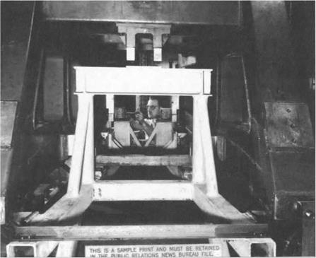
Figure 3. Heavily-instrumented static engine test cell, 1950s, with many hoses leading off for pressure measurements. [NACA, as reprinted in Lancaster 1959, Plate 2,24b.]

Test cells operate engines in confined spaces, and engine/test chamber interactive effects often produce erroneous measurements. For example, flexible fuel and pressure lines (which stiffen under pressure) may contaminate thrust measurements. This can be countered by allowing little if any movement of the thrust stand – something possible only under certain thrust measurement procedures. Other potential thrust-measurement errors are:

• air flowing around the engine causing drag on the engine;

• large amounts of cooling air flowing around the engine in a test cell have momentum changes which influence measured thrust;

• if engine and cell-cooling air do not enter the test cell at right angles to the engine axis, an error in measured thrust occurs due to the momentum of entering air along the engine axis;

• pressure difference between fore and aft of the engine may combine with the measured thrust.19

These can be controlled by proper design of the test cell environment or by making corrections in the data analysis stage.

b. Engine Flight Testing

In the 1940s and early 1950s, photopanels were the primary means for automatic collection of engine flight-test data. Early photopanels were mere duplicates of the

ENGINE TESTING

test-pilot’s own panel. Later the panels became quite involved, having many gauges not on the pilot’s panel. Large panels had 75 or more instruments photographed sequentially by a 35 mm camera.

After the flight film would be processed. Then using microfilm readers data technicians would read off instrument values into records such as punched cards. Data reduction was done by other technicians using mechanical calculators such as a Friden or Monroe. On average, one multiplication per minute could be maintained.20 This and the need to hand record each measurement from each photopanel gauge placed severe limitations on the amount of data that could be processed and analyzed. Time lag from flight test to analyzed data often was weeks.

The development of electrical transducers such as strain gauges, capacitance or strain-gauge pressure transducers, and thermocouples enabled more efficient continuous recording of data. They could be hooked to galvanometers that turned tiny mirrors reflecting beams of light focused as points on moving photosensitive

ENGINE TESTING

Figure 5. Photopanel instrumentation for XP-63A Kingcobra flight tests at Muroc Airbase, 1944-45. Upper photo shows the photopanel camera assembly. Its lens faces the back of the instrument photopanel shooting through a hole towards a mirror reflecting instrument readings. The lower left picture is the photopanel proper, consisting of several pressure gauges, two meters, and a liquid ball compass. The camera shoots through the square hole below the center of the main cluster. The lower right picture shows the test pilot’s own instrument panel. [Young Collection.]

ENGINE TESTING

Figure 6. Human computer operation at NASA Dryden Center, 1949, shown with a mechanical calculator in the foreground. [NASA E49-54.]

paper, giving continuous analog strip recordings of traces. Mirrors attached to 12-24 miniaturized pressure manometer diaphragms also were used.21 Such oscillograph techniques for recording wave phenomena go back to the 19th century,22 but by the 1950s had evolved into miniaturized 50-channel recording oscillographs (see Figure 10). By 1958, GE Flight Test routinely would carry one or two 50-channel CEC recording oscillographs in its test airplanes.

With 50 channels of data, one had to carefully design the range of each trace and its zero-point to ensure that traces could be differentiated and accurate readings could be obtained. Fifty channels of data recorded as continuous signals on a 12” wide strip posed a serious challenge. A major task for the instrumentation engineer was working out efficient and unambiguous use of the 50 channel capacity. Instrumentation adjusted the range and zero-point of each galvanometer to conform to the instrumentation engineer’s plan.

Another aspect of the instrumentation engineer’s job was to design an instrumentation package allowing for efficient adjustment of galvanometer swing and zero point. This amounted to the design of specific Wheatstone Bridge circuits to control each galvanometer. The 1958 instrumentation of the GE F-104 #6742, designed by George Runner, had a family of individual control modules hand-wired on circuit boards with wire-wound potentiometers to adjust swing. (Zero point was adjusted mechanically on the galvanometer itself.) Each unit was inserted in an aluminum “U” channel machined in the GE machine shop, with plug units in the rear and switches and potentiometer adjustments in the front end of the “U”. These interchangeable modules could be plugged into bays for 50 such units, allowing for

ENGINE TESTING

Подпись: Figure 8. GE data reduction and processing equipment, 1960. Three instrument clusters are shown. In the middle is a digitizing table for converting analogue oscillograph traces to digital data. A push of a button sends out digital values for the trace which are typed on a modified IBM typewriter to the left. The right cluster is a IBM card-reader/punch attached to a teletype unit mounted on the wall for transmitting data to and from the GE Evandale, Ohio, IBM 7090. On the left another IBM card reader is attached to an X-Y plotter. Various performance characteristics could then be plotted. [Suppe collection.]

Figure 7. Typical Oscillograph trace record; only 16 traces are shown compared to the 50 channel version often used in flight test. [Source: Bethwaite l%3. p. 232; background and traces have been inverted.)

speedy and efficient remodeling of the instrumentation. A basic fact of flight test is that each flight involves changes in instrumentation, and 742’s instrumentation was impressively flexible for the time. 100 channels of data could be regulated; two recording oscillographs were used.

Oscillograph traces are, of course, analog. By the latter 1950s data analysis was being done by digital computer. This meant that oscillograph traces had to be digitized. Initially it was done by hand. Later special digitizing tables let operators place cross-hairs over a trace and push a button sending digital coordinates to some output device. At GE Flight Test initially a modified IBM Executive typewriter would print out four digits then tab to the next position. Later output was to IBM cards.23 Typewriter output only allowed hand-plotting data, whereas IBM cards allowed input into tabulation and computer processing.

GE Flight Test-Edwards did not have its own computer facilities in the late 1950s and early 1960s. Some data reduction used computers leased from NASA/Dryden, which only ran one shift at the time. Sixteen hours a day, GE leased the NASA computer resources – initially an IBM 650 rotating drum machine, later replaced by an IBM 704 and then by an IBM 709 in 1962. Most data reduction was done, however, on the GE IBM 7090 in Evandale, Ohio. Sixteen hours a day, IBM cards were fed into a card-reader and teletyped to Evandale where they were duplicated and then fed into a data reduction program on the 7090; the output cards then were teletyped back to GE-Edwards for analysis and plotting. Much plotting was done by an automated plotter placing about 8 ink-dots per IBM card.

Electronic collection of data with computerized data reduction and analysis radically increased the amount of data that could be collected, processed, and interpreted. Numbers of measurements taken increased at the rate of growing computing power – doubling about every 18 months. The very same computerized data collection and processing capabilities were incorporated into sophisticated control systems for advanced aircraft such as the X-15 rocket research vehicle, the XB-70 mach 3 bomber, and the later Blackbird fighters. As aircraft and engine

ENGINE TESTING

Figure 9. As aircraft got faster they relied increasingly on computerized control systems. Left – hand chart shows the increase in maximum speed between 1940-1965. The right-hand diagram shows the increase in flight-test data channels for the same aircraft over the same period. [Source: Fig. 1, p. 241, and Fig. 4, p. 243, of Mellinger 1963.]

ENGINE TESTING

Figure 10. EDP unit installed at GE Flight Test, Edwards AFB, 1960. The rear wall contains two 2" digital tape units, amplifiers, and other rack-mounted components. A card-punching output unit is off the right. The horseshoe contains various modifiers, the left side for filtering analog data signals and the right for analog-to-digital conversion, scaling, and the like. At the ends of the horseshoe are a 51 channel oscillograph (left) and pen-plotter (right) for displaying samples of EDP processing outputs for analysis. [Suppe collection.]

control systems themselves became more computerized and dependent on ever­more sensors, engine flight test likewise had to sophisticate and collect more channels of data. Fifty channels was the upper limit of what could reliably be distinguished in 12” oscillograph film, and analyzing data from two oscillograph rolls per flight stretched the limits of manual data processing.

The only hope was digital data collection and processing. When data are recorded digitally, many inputs can be multiplexed onto the same channel. Multiplexing is a digital analog to use of a scanivalve that avoids problems of overlapping and ambiguous oscillograph traces by digital separation of individual variables. A further advantage of digital processing is that the data are in forms suitable for direct computer processing, thereby eliminating the human coding step in the digitization process.

GE got the contract to develop the J-93 engine for the B-70 mach 3 bomber. Instrumentation on this plane was unprecedented, exceeding its North American predecessor, the X-15. GE geared up for the XB-70 project, building a new mammoth test cell for the J-93 in 1959-60 with unusually extensive instrumentation (e. g, 50-100 pressure lines alone), introducing pulse-coded-modulation digital airborne tape data recording, developing telemetering capabilities, and contracting for a half-million dollar Electronic Data Processing (EDP) unit.

The EDP unit primarily was a “modifier” in the instrumentation scheme, filtering signals through analog plug-in filters, doing analog-to-digital conversions, and performing simple scalings. Data recorded on one 2” digital tape could be converted into another format (2” tape or punched card) suitable for direct use on the IBM 704,

ENGINE TESTING

Figure 11. Upper picture is the X-l 5 telemetry ground station ca. 1959. The bulk of the station is devoted to radar ground tracking of the X-l5. Only the recorder, plotter and bank with meters in the left portion are concerned with flight-test instrumentation. Lower picture is the Edwards AFB Flight Test Center telemetry ground station in the early 1990s. Computerized terminals and projected displays provide more extensive graphical analysis of performance data in real time. [Upper photo: Sanderson 1965, Fig. 19, p. 285; lower photo: Edwards AFB Flight Test Center.]

709, and 7090. It also had limited output transducers that produced strip or oscillograph images for preliminary analysis. The surprising thing about this huge EDP unit is that it had no computer – not if we make having non-tape “core” memory the minimal criterion for being a computer. The decision was to build this device for data reduction, then “ship” the data via teletype to GE-Evandale for detailed processing and analysis.

In telemetry signals collected by transducers are radioed to the ground, as well as sent to on-board recorders, where a ground station converts them to real-time displays – originally dials, meters, and X-Y pen plotters, but today computerized displays, sometimes projected on large screens in flight-test “command centers.” Test flights are very expensive, so project engineers monitor telemetered data and may opt to modify test protocols mid-flight.24 Telemetry provides the only data when a test aircraft crashes, destroying critical on-board data records. GE Flight Test developed telemetering capabilities in preparation for the XB-70 project, trying them out in initial X-15 flights.

The X-15 instrumentation was a trial run for the XB-70 project (both were built by North American), although the X-15 relied primarily on oscillographs for recording its 750 channels of data.25 With the XB-70 project, the transition from hand-recorded and analyzed data to automated data collection, reduction, and analysis is completed. The XB-70B instrumentation had about 1200 channels of data recorded on airborne digital tape units. Data reduction and processing were automated. Telemetry allowed project engineers to view performance data in real time and modify their test protocols. Subsequent developments would sophisticate, miniaturize, and enhance such flight-test procedures while accommodating increasing numbers of channels of data but do not significantly change the basic approach to flight test instrumentation and data analysis.

A supersonic test-bed was needed for flight test of the XB-70’s J-93 engines. Since the J-93 was roughly 6’ in diameter – larger than any prior jet engine – no

ENGINE TESTING

Figure 12.7 Modified supersonic B-58 for flight testing the J-93 engine that would power the XB-70 Mach 3 supersonic bomber. A J-93 engine pod has been added to the underbelly of the airframe. [Suppe collection.]

established airframe could use the engine without modification. GE acquired a B-58 supersonic bomber which it modified by placing a J-93 engine pod slung under the belly. Once the aircraft was airborne the J-93 test engine would take over and be evaluated under a range of performance scenarios.

The Aft Fan Component

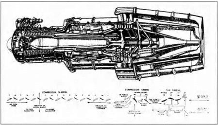
The aft fan required the mechanical design of a new type of blading, with relatively high temperature turbine blades – or, as GE called them, turbine buckets – in the inner portion and relatively cold fan blades of the opposite camber in the outer portion; GE dubbed these blades “bluckets” (see Figure 10). The aerodynamic

The Aft Fan Component

Figure 9. John Blanton, Richard Novak, Linwood Wright, key contributors to General Electric’s aft-fan development.

design of the turbine blading fell within the state of the art, whether the fan component consisted of one stage or two. But the same was not true of the fan blading. Considerations of weight and simplicity strongly favored a single stage fan. As is always the case, the thermodynamic cycle design of the fan component in­volved a complex set of trade-offs. The CJ805 turbojet produced 11,000 pounds of take-off thrust at a specific fuel consumption – i. e. pounds of fuel per hour per pound of thrust – around 0.70. Blanton found that a 1.56 bypass ratio aft fan behind the CJ805 could increase the take-off thrust to 15,000 pounds at a specific fuel consumption as low as 0.55, a quantum jump in both parameters! The one issue was the thrust-to-weight ratio of the engine, which depended on the weight of the fan component. The fan would have to pass 250 lbs/sec of air at a pressure-ratio of 1.6 with an installed efficiency no less than 0.82. Could this be achieved in a single stage? It was far beyond any single compressor stage GE had ever designed before, or for that matter any stage that had ever been in flight. Wright was nevertheless insistent that it could be done.54

The detailed aerodynamic design of the fan was predicated on two crucial decisions. The first was to set the tip Mach number of the fan at 1.25. Klapproth’s 1400 ft/sec tip-speed design had shown that the losses in appropriately designed blading correlated continuously with those in conventional blading up to a Mach number of 1.35. Wright’s 1260 ft/sec transonic rotor, which had a design tip Mach number of 1.25, had been predicated on the 90 percent speed results of Klapproth’s design.55 In effect, based on his experience at NACA, Wright decided that losses associated with shocks would not become obtrusive so long as the tip Mach number did not exceed 1.25. His high confidence in the design, which was questioned by several of GE’s experienced compressor designers, came in large part from the safety margin he believed he had introduced in choosing the 1.25 tip Mach number.

Fan Aerodynamic Design-A New Computer Method The second crucial decision was to adopt a novel analytical design approach. A distinctive feature of both Klapproth’s 1400 ft/sec and Wright’s 1260 ft/sec NACA

The Aft Fan Component

Figure 10. Blucket from General Electric CJ805-23 fan engine. Inner section is turbine “bucket,” drawing energy from jet exhaust, outer section is fan blade, pressurizing bypass flow, hence the hybrid term “blucket.” [Wilkinson, cited in text, p. 32.]

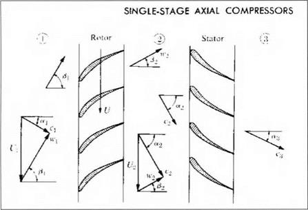
rotors “was a fairly elaborate three-dimensional design system which allows both arbitrary radial and axial work distributions”56 within the blade row. Just as the annulus or flow area must contract in a high-pressure-ratio, multistage compressor, the flow area within a high-pressure-ratio blade row must contract between the leading and trailing edges far more than in conventional blade rows. Furthermore, high Mach number airfoil profiles are very sensitive to incidence angle. As a conse­quence, radial equilibrium effects, redistributing the flow radially, becomes important within blade rows in this type of stage, and not just from stage to stage as in more conventional compressors.

One of the first computer programs GE had developed after delivery of its IBM – 704 digital computer in 1955 solved the radial equilibrium problem in multistage axial compressors. The program employed the so-called streamline-curvature method, an iterative procedure for solving the inviscid flow equations. Specifically, an initial guess is made on where the streamlines lie radially in the spaces between each blade row throughout the compressor, and the flow along these streamlines is calculated; the streamlines are then relocated iteratively until the continuity equation is satisfied.57 When used in design, the work done and losses incurred across each blade row are specified as input along the streamlines, and the flow analysis results are then used to select appropriate standard airfoil profiles for the blades.58 Such an iterative approach was out of the question without digital computers, for the total number of calculations required is immense. Even with an IBM-704, the solution for a single operating point of the 17-stage J-79 compressor would take two or three hours, depending on the initial streamline location guess. The advance in analytical capability, however, justified this. The radial redistribution of the flow throughout a multistage compressor could be calculated with reasonable confidence for both design and off-design operating conditions. Streamline-curvature computer programs revolutionized the analytical design of axial compressors.59

Novak’s strong advocacy of streamline-curvature methods had been one of the chief reasons GE had developed this program in the first place. In the original program radial equilibrium was imposed only in the open spaces on either side of each blade row. Novak now proposed that GE’s streamline curvature program be specially modified to allow radial equilibrium to be imposed at select stations within blade rows. The streamlines and calculation stations for the fan are shown in Figure 11. In effect, the modified procedure “fools the IBM computer into thinking it is going through a series of stators with no swirl in the inlet of the compressor, through a series of rotors with small energy input through the rotor proper, and a series of stationary blade rows when it actually computes through the complete stator.”60 The second key decision in the design of the fan was to modify the streamline-curvature computer program and use it in designing the rotor and stator airfoils.

The Aft Fan Component

Figure 11. Schematic illustration of streamline curvature method used in fan design (looking sideways at the engine). Initial positions of “streamlines” are assumed, flow conditions are then computed at each of the numbered stations; streamlines are then iteratively relocated until continuity conditions are satisfied. The unusual feature in this diagram is that computational stages aie included within each blade row (i. e. stations 4, 5, 6 & 7 are within rotor). [Wright and Novak, op. cit., p. 5; Figures 11-17 are all from this paper, cited in note 7 of the text.]

Specifically, the following parameters were specified as input and the requisite shape of the airfoils was inferred from the flow solution: (1) loss or entropy change distributions, both radially and along stream surfaces through the blades and annulus; (2) energy or work distribution radially and along stream surfaces; (3) blade blockage – i. e., a reduction in flow area within the blade rows; and (4) an allowance for boundary layer thickness along the casing wall. The solution determined (circumferentially average) velocities and pressures at each station along the streamlines. Blade surface velocities could then be inferred by assuming a linear cross-channel variation in static pressure; and blade contours were inferred from the (circumferentially average) relative flow angles at each station by assuming a blade thickness distribution and a distribution of the difference between air and metal angles within the blade row.

The choice dictating the values of the aforementioned parameters is based on judgment, prior test data and on a knowledge of the probable mechanical re­quirements of blade-thickness distribution, and so on…. It is to be recognized from the start that the entire procedure presupposes an iteration, with many variables, to a selfconsistent solution. Hence, each input parameter itself was considered as subject to change.61

No cascade airfoil contours had ever been designed by means of such an elaborate procedure before. The “Arbitrary Blade Contour” Program, as Wright called the modified program, gave him good design control in a design that stood well outside the established state of the art.62

Its complexity and sophistication notwithstanding, this analytical method fell far short of providing a scientifically rigorous or exact calculation of the flow in the fan. First of all, the program was solving the inviscid equations of motion, with viscous losses simply estimated and superposed numerically at calculation stations. In particular, the viscous boundary layers on the blade sur­faces were ignored, their effects represented by superposing on the inviscid flow a stipulated sequence of thermodynamic losses distributed linearly with axial distance.63

Second, the actual rotor blades and stator vanes indicated in Figure 11 were not literally included in the analysis. The streamlines shown in the figure were really axisymmetric stream surfaces in the calculation – not just between blade rows, but within them as well. The physical presence of the blades was represented by a numerically superposed blockage of the flow within the blade rows. The velocities and pressure calculated at each axial station within a blade row were accordingly treated within the analysis as if they were uniform around the circumference. The velocities at the blade surfaces were then calculated, in a subsidiary program, by stipulating the number of blades and assuming a linear variation in pressure from one blade surface to the next. The method thus replaced the actual three-dimensional geometry and flow by a highly idealized model; it did not include even a two­dimensional blade-to-blade flow solution of the sort that had been promoted by Chung-Hua Wu at NACA.64

Third, no effort was made to determine the precise locations of the shocks, much less to determine their interaction with airfoil boundary layers. The American Society of Mechanical Engineers’ paper by Wright and Novak describing the design of the fan and the method followed never mentions shocks. Yet shocks were surely present, for the design relative incident velocity was supersonic over all but a small fraction of the blade span, ranging from a Mach number of 1.25 at the tip to 0.98 at the hub. The shocks were taken into account only in the input distributions of losses and work specified within the rotor blade row; the shock structure assumed for this purpose was based on two-dimensional Schlieren photographs of the sort shown in Figure 8.

In short, what the analytical method did was to provide a highly idealized analysis of radial equilibrium effects within the blade rows. High Mach number blading is sensitive to deviations in incidence angles. The principal source of such deviations was thought to be radial migration of streamlines within the blade rows and blockage caused by the casing wall boundary layers. The method yielded blade contours in which radial equilibrium effects within the blade rows were consistent, under the assumptions of the analysis, with the computed incidence angles. The inputs assumed in the design were based on judgment and previous test data, reflecting Wright’s experience at NACA. A large number of passes through the design procedure (each requiring more than 20 minutes of IBM 704 computer time) were made, with these inputs changing, before a result emerged that was deemed adequately “selfconsistent.” The analytical method, for all its sophistication, was a tool in a design that remained essentially a product of judgment.

A central element of this judgment was to maintain the diffusion factors across the blade rows within the established limits, subject to Klapproth’s proviso (quoted earlier) that the velocity distributions within the blade rows not depart too radically from those of conventional airfoils. The computer program served to define the radial relocation of the stream surfaces within the blade rows, across which the diffusion factor was calculated, and it helped assure that the design would fall within the regime Klapproth had singled out. How much the blades designed on the basis of it differed from blades that might have been obtained, exercising the same judgment, from the computationally less intensive methods followed by Klapproth and Wright at NACA is an open question.65

ALUMINUM SHORTAGES AND WORLD WAR II: AIR FORCES EMBRACE WOOD

Despite the arguments advanced by proponents of wood, the mere threat of war did little to stimulate renewed development of wooden airplanes by potential belligerents. Germany, the main source of renewed military tensions, showed little interest in wooden airplanes. The expansion of the German air force, begun soon after the Nazi seizure of power, was also accompanied by a huge expansion of Germany’s aluminum capacity; by 1939 Germany had surpassed the United States and become the largest aluminum producer in the world. This expansion was dictated more by National Socialist Autarkiepolitik than by projected needs of the Luftwaffe, but this vast capacity no doubt dampened German interest in developing wooden airplanes.23

The raw material situation was quite different in Britain, where serious rearmament began in 1936. The expansion of the RAF occurred simultaneously with the shift to aluminum stressed-skin construction, yet British aluminum production in 1939 amount to only 15 percent of Germany’s. British strategy was to rely on Canadian and American production to supply its needs. Already in April 1939, the British Air Ministry estimated that imports would have to supply two – thirds of British requirements; these estimates proved low.24 Although the Air Ministry appeared confident of its ability to obtain the necessary aluminum supplies, this dependence apparently made the British more willing to continue the use of wood in non-combat airplanes, primarily trainers. In the late 1930s, the RAF stepped up purchases of wooden training aircraft, and by 1943 all British-made training aircraft in production used all-wood or wooden-winged construction.25

Yet Britain’s use of wood was not confined to non-combat aircraft, due largely to the efforts of a single major British aviation firm, the De Havilland Aircraft Company. This firm designed the most famous wooden airplane of the war, the de Havilland Mosquito, a twin-engine bomber, fighter-bomber, night fighter and reconnaissance airplane. The Mosquito was conceived by the de Havilland firm shortly after the Munich crisis in 1938. Geoffrey de Havilland, the company’s founder, proposed building a fast unarmed bomber, protected only by its speed and maneuverability. The de Havilland design dispensed with the anti-aircraft guns standard for bombers at the time. Without defensive armament, claimed de Havilland, his design would fly faster than the opposing fighters. He also noted the advantages of wood for production in wartime, when it would not compete for resources with the metal-using industries. The de Havilland proposal was presented to the Air Ministry in October 1938, but the unconventional design generated little interest. After the declaration of war the following September, the de Havilland firm pressed its case for the design before the Air Ministry, and in December de Havilland received an order for the Mosquito prototype. The Mosquito first flew in November 1940, a mere 11 months after serious design work began. Performance exceeded expectations, and the Air Ministry placed large production orders for the airplane.26

Production deliveries began in July 1941. The airplane soon proved itself in combat, becoming “one of the most outstandingly successful products of the British aircraft industry during the Second World War.” The Mosquito excelled in speed, range, ceiling and maneuverability, making it useful in a variety of roles. Even before the prototype flew, De Havilland began developing reconnaissance and night-fighter variants.27 With a range of over 2000 miles, the original reconnaissance version could photograph most of Europe from bases in Britain at a height and speed that made it practically immune to enemy attack. Later modifications extended the range of the reconnaissance version to over 3500 miles.28 Studies of the Allied air offensive against Germany showed the Mosquito to be far more efficient at placing bombs on target than the large all-metal bombers that formed the backbone of the bombing campaigns. Compared to the heavy bombers, the Mosquito was cheaper to build, required a much smaller crew, and suffered a much lower loss rate, only two percent for the Mosquito compared to five percent for the heavy bombers. One British study calculated that the Mosquito required less than a quarter of the investment to deliver the same weight of bombs as the Lancaster, the main British four-engine bomber.29

The Canadians also got involved in wooden aircraft production. The Canadian case is particularly instructive because of its similarity with the United States in technology and availability of materials. During the interwar period, Canada had built up a small aircraft industry, though its design capabilities remained limited. For armaments, Canada remained largely dependent on Britain, and the Canadian armed forces followed other Commonwealth countries in standardizing on British materiel. As the British rearmed in the late 1930s, they looked to Canada as a possible source of aircraft and munitions, in addition to Canada’s traditional role as a supplier of raw materials. The Canadians, however, were loathe to finance expansion of their production capacity without guaranteed orders from Britain. In November 1938, the British finally placed a significant order with the Canadian aircraft industry for 80 Hampden bombers and 40 Hurricane fighters, accepting a 25 percent higher cost as the price for creating additional aircraft capacity.30

Canada remained a reluctant ally even after joining Britain in declaring war on Germany. Nevertheless, Canada did agree to host the British Commonwealth Air Training Plan, an ambitious program that eventually provided nearly 138,000 pilots and other air personnel for the British war effort. This program would require an estimated 5,000 training airplanes. The Canadian subsidiary of De Havilland was already producing the Tiger Moth, an elementary biplane trainer of wood construction that would be used for the training program. But Britain discouraged Canadian production of the more sophisticated training airplanes, insisting instead on supplying these types from their own production or American purchases.31

This situation changed radically with the fall of France. In the bleak summer of 1940 a British defeat seemed a very real possibility. Britain cut off shipments of aircraft and parts to Canada, and no replacements seemed likely from the U. S. for quite some time. It appeared that Canada might be forced to depend on its own resources for defense.32

One key Canadian resource was timber. In a report dated May 1940, J. H. Parkin proposed a program for developing wooden military airplanes in Canada. Parkin, director of the Aeronautical Laboratories at the National Research Council (NRC), presented strong technical arguments in favor of wood structures. Parkin also stressed Canada’s large timber resources, which included large reserves of virgin Sitka spruce. Parkin proposed that “the design and construction of military aircraft fabricated of wood should be initiated in Canada immediately.”33

These proposals helped launch a major Canadian program for producing wooden airplanes. Air Vice-Marshall E. W. Stedman, the chief technical officer in the RCAF, strongly advocated the construction of wooden airplanes. In London, the Ministry of Aircraft Production sought to discourage “inexperienced Canadian designers” from developing their own airplanes. Nevertheless, the RCAF continued to urge production of a wooden combat airplane in Canada; these efforts eventually led to Canadian production of the Mosquito.34 De Havilland Canada built a plant with a mechanized assembly line for Mosquito production; this plant reached a production rate of 85 airplanes monthly by mid-1945.35

Despite British skepticism, the Canadian government strongly supported the development of innovative wooden airplanes of Canadian design. In coordination with the RCAF, the NRC launched a substantial research program to develop molded plywood construction. In July 1940 RCAF and NRC staff traveled to the U. S. to investigate the latest techniques in wooden aircraft construction. They were especially impressed with Eugene Vidal’s process. Vidal was former Director of Civil Aeronautics at the Commerce Department and an enthusiast of the “personal” airplane. Vidal had started research on molded plywood after his unsuccessful attempt to develop a $700 all-metal airplane while at the Commerce Department.36

By the fall of 1940, Vidal had become the leading American developer of plywood molding techniques, due to Clark’s failure to secure military support for Duramold.37 The Canadian government asked Vidal’s company to build an experimental fuselage for the Anson twin-engine training plane, a British design then being built in Canada. The fuselage was a success, and in 1943 a Canadian company began manufacturing the fuselages under license to Vidal. From 1943 to 1945 over 1000 of the Vidal Ansons were built in Canada. A rugged, reliable airplane, the Vidal Ansons found wide use as civil aircraft after the war. The Vidal Ansons provided one of the largest and most successful applications of molded plywood to airplane structures during the war.38

The United States also launched a major wooden airplane program during World War II, but not until severe aluminum shortages threatened to curtail aircraft production. But unlike the British and Canadians, American support for wooden airplanes remained highly ambivalent.

American rearmament did not begin in earnest until after the German invasion of the low countries in May 1940, when President Franklin Roosevelt startled Congress with his 50,000-airplane program, which called for roughly a ten-fold increase over current production. Before FDR’s dramatic announcement, military planners had repeatedly insisted that aluminum supplies were ample to meet any emergency. Although Air Corps planners had given some attention to increasing the capacity of airplane plants, they had “virtually ignored” possible shortages of aircraft materials and accessories. Conditioned by interwar parsimony, the planners had little inkling of the numbers of airplanes that the President and armed forces would demand, especially when the U. S. became involved in a shooting war.39

American aircraft manufactures began publicly reporting serious aluminum shortages in late 1940 as production accelerated to meet British as well as American needs. In early 1941, the U. S. Office of Production Management finally acknowledged that the country was facing a serious aluminum shortage, and began restricting civilian consumption of aluminum. The federal government responded by financing a massive increase in aluminum refining capacity.40 But in the meantime the military would have to find other materials if it hoped to meet the President’s production goals.

With the onset of the aluminum shortage in early 1941, the Army rushed to expand the use of wood in non-combat airplanes. Early in the year, Wright Field began asking some of the Army’s largest suppliers to establish programs for converting aluminum airplane parts to plywood or plastics, and by the mid-1941 these programs were well under way. North American Aviation had an especially active substitution program for the AT-6, the most widely used advanced trainer in the war. Three major manufacturers were developing all-wood bombing trainers for the Army; two of them, Beech and Fairchild, received production contracts before the end of the year. The Air Corps also accelerated orders for its wood primary trainers already in production; by August 1941 Fairchild was building four PT-19 trainers a day. Cessna began building a twin-engine trainer for the Army based on its commercial light transport. Wooden airplanes appeared poised to play a major role in American mobilization.41

Plans for wooden airplanes grew even more ambitious after Pearl Harbor. By March 1942, Wright Field had plans to order some 16,000 wooden airplanes,

28.0 wooden propellers and 3,000 wooden gliders. Wright Field staff estimated that the substitution program would save some 45 million pounds of aluminum in the production of existing airplanes, largely by using plywood for non-structural parts. The Army Air Forces also ordered 400 Fairchild AT-13s, a new all-wood crew trainer, a fivefold increase over the original order. In an even more ambitious project, the Army launched plans for quantity production of a large wooden transport to be developed by Curtiss-Wright, the C-76. By December 1942 Curtiss-Wright had received orders for 2600 C-76 airplanes at a total estimated cost of over $400 million, including the construction of two huge new factories.42

At first glance, the American wooden airplane program appears almost as successful as those of Britain and Canada. The Army and Navy purchased some

27.0 airplanes that used wood for a significant part of the structure, along with nearly 16,000 gliders built largely of wood. These figures imply that wood airplanes made a significant contribution to the U. S. war effort, amounting to some 9 percent of the 300,000 airplanes produced for the military from July 1, 1940 to Aug. 30, 1945 43 But a closer look reveals this contribution to be less than it seems. With one exception, none of these wooden types were for combat, and the one combat airplane never entered production. The vast majority were relatively light-weight, low-performance training airplanes, mostly based on designs from the 1930s that did not take advantage of synthetic adhesives or molding techniques. In terms of airframe weight, a more reliable index of manufacturing effort, wooden airplanes accounted for only about 2.5 percent of the total44 Furthermore, most of the models produced in quantity used wood for just a small part of the total structure, such as the wing spars.

When it came to developing new designs, the American wooden airplane program was almost a complete failure. Problems occurred in design, production and maintenance. One of the most disastrous design failures was the Curtiss-Wright C – 76, a large twin-engine transport designed to carry a 4500-pound payload. Curtiss-Wright was one of the Army’s leading suppliers, but it had no recent experience designing wooden airplanes. The project began in March 1942 with an order for 200 airplanes; the Army ordered an additional 2400 before the first prototype was completed. When the C-76 prototype was finished a mere 11 months later, it proved overweight, under strength, and difficult to control in flight. In June 1943, repeated failures in static tests led Wright Field to reduce the permissible gross weight to 26,500 pounds pending successful strengthening of the structure, leaving the airplane with a pitiful payload of 549 pounds. The project became the subject of a Congressional investigation, and in July Gen. H. H. Arnold canceled the project at a loss to the Army of $40 million 45

By the summer of 1943, aluminum had become plentiful in the United States, and Wright Field began canceling production of wood designs in favor of proven metal models. In September, J. B. Johnson reported to a NACA committee that the Army was “discouraging the use of wood construction” due to “disappointing results” with wood airplanes.46 The Army also cut off funding for wood research being conducted at the Forest Products Laboratory in Madison, Wisconsin.47 The momentum of some projects carried them forward for almost another year, but in time they too were canceled. Howard Hughes was able to continue working on his giant flying boat despite military opposition, since his funding came from the Defense Plant Corporation rather than the military. But Hughes was engaged in an act of technological hubris that was bound to fail, despite the tremendous technical skill that he brought to the project.48