Category How to Find the Apollo Landing Sites

Moon Geology

The lunar crust is a three layer cake affair, with an upper regolith, lower regolith, and then the mantle layer. The upper regolith extends from 3 feet to 60 feet in depth, and is the result of millions of years of constant bombardment of meteorites and geologic stress from heating and cooling. The lower regolith extends to a depth of 12 miles, and is made up of basalt rocks. Below the two layers of regolith is the mantle, consisting of less rigid material that is low in iron content. Scientists have postulated from the available data gathered from Apollo and unmanned lunar mis­sions that the core of the Moon is small and iron-rich.

There are three major types of features that dominate the surface of the Moon: impact craters, marias (or seas), and highlands. Most familiar are the many craters, caused by the eons of meteorite impacts on the surface. The wide, dark seas are composed of iron and titanium rich volcanic rock known as basalts. And the high­lands are made up of various types of silicate type rocks.

Unique to the Moon’s geology in the highlands, and not found on Earth, is the presence of a type of rock called KREEP. This acronym is formed from potassium (chemical symbol K), rare-earth elements (REE), and phosphorus (chemical sym­bol P). First discovered from the samples brought back by Apollo 12, KREEP is made up of normally incompatible elements, and represents part of the evidence for the formation of the Moon. The leading theory for the Moon’s formation is that it was formed from the remains of an ancient impact between the Earth and a Mars­sized proto-planetary body.

The Apollo missions provided detailed knowledge of the nature of the lunar soil and rocks, and evidence for the impact theory of the lunar genesis.

Apollo 17

Crew: Commander Gene Ceman CM Pilot Ron Evans LM Pilot Dr. Harrison Schmidt

Command Module America Lunar Module Challenger

Accomplishments: Last Moon landing. Longest lunar stay of 74 hours and 59.5 minutes. Returned 243 pounds of lunar samples.

Apollo 17

Fig. 9.1 Apollo 17 Insignia. Courtesy of NASA

Apollo 17

The Apollo 17 landing in the Taurus-Littrow Valley was the last Apollo mission, with Apollo 18, 19, and 20 terminated due to budget cuts. As of this writing, Apollo 17 proved to be the last time man set foot on the Moon. Apollo 17 was the final J-type mission, distinguished from the previous G – and H-series missions by expanded and improved hardware, a larger instrumentation package, and extended exploration and sampling range using the Lunar Roving Vehicle, or LRV. The pri­mary objectives of Apollo 17 were threefold:

• Conduct geological observations and collect samples of the Taurus-Littrow region for data of the specific area. The Apollo 17 mission collected Taurus – Littrow information for comparison with geologic data from the previous Apollo mission regions. This objective was aided with the extended range provided by the LRV. The LRV carried onboard two experiments, the Lunar Traverse Gravimeter (LTG) and the Surface Electrical Properties (SEP) experiment.

• Deploy and activate a new version of the Apollo Lunar Surface Experiments Package, or ALSEP, that included five experiments not previously deployed by the earlier Apollo missions. The ALSEP included a heat flow experiment; lunar seismic profiling experiment (LSPE); lunar surface gravimeter (LSG); lunar atmospheric composition experiment (LACE); and lunar ejecta and meteorites (LEAM).

• Conduct lunar orbiting experiments from Apollo 17’s Service Module, including a lunar sounder, infrared scanning radiometer, and far-ultraviolet spectrometer.

Apollo 17 was the first and only Apollo mission that included a scientist as part of the crew. Geologist Jack Schmitt served as the LM pilot, with veteran Astronaut Gene Cernan serving as the Apollo 17 Commander and flying the LM. Both Gene Cernan and CM pilot Ron Evans received extensive training in geology and lunar science, with Ron Evans concentrating on visual recognition and observation of geological features from long distance.

The original crew assignment was Gene Cernan, Ron Evans, and Joe Engle, a former X-15 pilot credited with 16 X-15 flights. Three of Engle’s X-15 flights exceeded the altitude of 50 miles which earned him astronaut wings prior to his joining Apollo. The normal NASA practice was to have the backup crew of a mis­sion be the primary crew three missions later. Cernan, Evans, and Engle served as the backup crew for Apollo 14, and as such were the primary crew for Apollo 17. Jack Schmitt was originally scheduled for Apollo 18 as the LM pilot. With the cancellation of Apollo 18, 19, and 20, there was pressure to include a scientist on Apollo 17. Thus, Schmitt replaced Engle as the LM pilot for Apollo 17. Prior to the Apollo 17 mission, Jack Schmitt’s claim to fame was cleaning up a transmission verbal faux pas of Astronaut Tom Stafford on Apollo 10 by rephrasing Stafford’s description of a crater as “bigger than Schmitt!”.

Joe Engle would never fly to the Moon, but he did fly as commander on Space Shuttle STS-2 with Shuttle pilot and future NASA Administrator Richard Truly, and as mission commander of STS-51-1. Engle is the only astronaut to fly both the X-15 and the Space Shuttle winged spacecraft into space, and to control and land the Space Shuttle manually.

The LM Challenger landed within 200 m from the planned landing coordinates. Three EVA’s were conducted, with the first EVA tasks including: the deployment of the ALSEP, deployment of the first set of geophones and explosive charges as part of the LSPE, and conducting a cosmic ray experiment using the Cosmic Ray Detector (CRD). During the second EVA, Astronauts Cernan and Schmitt used the LRV to collect core samples, dig trenches, and traverse from Nansen Crater, Lara Crater and various points along the way. These stops were made along the way to collect data from the Lunar Traverse Gravimeter (LTG) and the Surface Electrical Properties (SEP) experiment, and deploy additional LSPE geophones and explosive charges. The third EVA, additional sampling stops and traverse gravimeter mea­surements were made. Additional geophones and explosive charges for the LSPE were deployed, and the EVA ended with the retrieval of the neutron flux probe from the deep drill core hole. Each EVA lasted over 7 hours.

The Taurus-Littrow Valley is fairly easy to identify with a telescope. The site is at the southeastern rim of the Sea of Serenity and intersects the Sea of Tranquility.

Apollo 17

The landing site selected for Apollo 17 was in the Taurus-Littrow Valley on the southeastern rim of Sea of Serenity. Obtaining samples that would determine how this region of the Moon formed particularly interested lunar scientists in this landing site. The two primary objectives were obtaining samples of highland material that were older than the Imbrium impact and investigating the possibility of young, explosive volcanism in this region. Taurus-Littrow was one of several sites consid­ered, along with the Tycho crater, Copernicus crater, and the Tsiolkovsky crater on the far side of the Moon. The Tycho crater was considered too dangerous because of the roughness of the terrain. Copernicus crater was a low priority site. A far side mission to Tsiolkovsky crater created significant communications problems, with the necessity of placing a constellation of expensive communication relay satellites in orbit around the Moon to provide continuous communications with Mission Control and the command module. The Taurus-Littrow site was selected with the anticipa­tion of sampling ancient highland material and young volcanic material in the same landing site. The Taurus-Littrow site also provided the sampling of Tycho ejecta, and geologists suspected some of the craters in the area could be volcanic vents.

Apollo 17

As an observer increases magnification, under steady seeing, the landing area can be seen to have both lighter or darker material. The geologists referred to this mate­rial as light mantle and dark mantle material, stemming from suspected lava flows.

Apollo 17

Fig. 9.5 Zoom-in on the Apollo 17 landing site. Courtesy of the author

The chosen landing site is in an area between two geological massifs, or moun­tain masses, where observational evidence showed dark material from either land­slides or pyroclastic deposits. This dark mantle material is covered with small craters, which scientists at the time postulated either volcanic or meteoric in origin. The results of the Apollo 17 geological studies suggest that approximately 100 mil­lion years ago, lava seeped to the Moon surface and flooded and pooled to form the Taurus-Littrow area and Sea of Serenity. The lava flows apparently were accompa­nied by fire fountains, which formed both orange and dark-colored beads in the soil. Several samples of lunar soil from Taurus-Littrow contained orange glass beads, causing the samples to have an orange hue. Fire fountains also accounts for the dark glassy material collected at the Taurus-Littrow landing site.

Apollo 17

Fig. 9.6 LRO view of the Apollo 17 landing site from 50 Miles Above. Photo courtesy of NASA and Arizona State University

Figure 9.6 is one of the LRO’s clearest photos of an Apollo landing, with the Challenger’s descent stage clearly visible. Since the Moon has no weather or envi­ronmental conditions that can inflict weathering on the soil, the tracks of the lunar rover and the footprints of the astronauts can be easily seen. Unfortunately, this cannot be seen with backyard telescopes. The LRO photographs are taken at an altitude of 50 miles above the lunar surface.

Also visible in this picture is a cluster of craters. It has been determined from the Apollo 17 mission, that much of the main crater cluster was the secondary impact result of the massive Tycho impact less than 95 million years ago. Most of these secondary impact craters were the result of eject spreading out downrange from the Tycho crater. The downrange pattern formed points directed at Tycho. The lighter colored material originated from landslides caused by the secondary ejecta from Tycho hitting the Taurus-Littrow massifs.

Apollo 17 LM Challenger Descent Stage

Fig. 9.7 A closer view from the LRO of the Challenger descent stage. Photo courtesy of NASA and Arizona State University

Apollo 17
Подпись: LEAM
Подпись: Packing material
Подпись: 4— RTG -Central Station
Подпись: Geopbone 2
Apollo 17

Apollo 17Apollo 17 ALSEP LROC NAC M168000580R

Fig. 9.8 LRO view of the Apollo 17 ALSEP with amazing detail of the Apollo 17 ALSEP setup. The Lunar Surface Gravimeter (LSG) and the Lunar Seismic Profiling Experiment (LSPE) and its four associated geophones can also be seen. Photo courtesy of NASA and Arizona State University

Apollo 17

Fig. 9.9 CM pilot Ron Evan’s view of the Taurus-Littrow landing site. Note the massifs that are prominent surrounding the landing site. Courtesy of NASA

Apollo 17

Fig. 9.10 This mosaic panorama of the Taurus-Littrow valley shows the mission viewpoint of the landing site. In the distance the massifs that dominate and define the area can be seen. The Lunar Rover and Astronaut Harrison (Jack) Schmitt are also shown in this panorama. Courtesy of NASA

Apollo 17

Fig. 9.11 The LRV aka the Lunar Rover

The Apollo 17 LRV carried onboard two experiments to obtain data during the lunar traverses. One experiment, the Lunar Traverse Gravimeter (LTG) measured the value of the Moon’s gravity around the Taurus-Littrow area. The LTG, by mea­suring the minute variations of gravity, provided data to determine the shape and depth of the bedrock. At each stop, the astronauts read the LTG readings over voice communications link to Mission Control. Twenty-six measurements were success­fully taken during the first, second and third traverses. This was fortunate, since the similar Lunar Surface Gravimeter (LSG) experiment, part of the ALSEP, failed to function due to a design error.

The other experiment, known as the Surface Electrical Properties (SEP) experi­ment looked for layering in Taurus-Littrow soil by transmitting radio waves into the Moon surface, using interferometry from the radio wave returns, and identifying the layers of the lunar soil. Readings were taken at each stop, with the SEP transmitter set up each time a distance away from the LRV, and the receiver mounted on the front of the LRV receiving the reflected radio signal.

Apollo 17

Fig. 9.12 History’s First Extraterrestrial Fender Bender and Body Repair! Courtesy of NASA

An interesting and historically humorous footnote to the Apollo 17 mission was mankind’s first car accident and car repair on another world. Figure 9.12 shows the makeshift repair on the right rear fender of the lunar rover. Apparently during the first EVA, Gene Cernan brushed against the Lunar Rover, and a hammer in his spacesuit shin pocket caught the LRV’s right rear fender and knocked off half of it. As a result of the broken fender, the rover kicked up a dust plume while moving. The dark dust covered the astronauts, which absorbed the heat from the sunlight and could potentially cause overheating problems for Cernan and Schmitt. The abrasive moon dust also could cause scratching of the astronauts’ visors, and affect the operation of the various latches, hinges, and joints of the LRV. At the beginning of EVA 2, using the universal fix-all duct tape, Cernan was able to re-attach the fender piece after two tries. The taped on fender lasted for over four of the 7 hours EVA 2. However, the duct tape lost some of its stickiness because of the ubiquitous moon dust. For the rest of EVA 2, time was lost as the astronauts frequently used a moon dust brush to clean off the LRV, equipment and themselves. During the break between EVA’s, Cernan and Schmitt fashioned a makeshift fender out of four lami­nated maps and duct tape while inside the relatively cleaner LM. The tape worked better this time, and the new fender was attached by using clamps from the optical alignment telescope lamp. The makeshift fender lasted for the all of EVA 3.

Apollo 17

Fig. 9.13 A large lunar Rock during found during an LRV traverse. Courtesy of NASA

Boulders of various sizes are scattered throughout the Taurus-Littrow valley. At the ALSEP area, deployed west of the Apollo 17 landing site, the boulders aver­aged about 4 m in size and were found to be more numerous than in other areas of the valley. Figure 9.13 illustrates the large rock where one of the LSPE geophones was placed.

Apollo 17

Fig. 9.14 An LSPE explosive charge. Courtesy of NASA

The LSPE included explosive charges that were placed at distances away from the geophones, which when activated, sent shock waves through the lunar soil. A total of eight charges were deployed at distances of between 100 m and 3.5 km from the LSPE at the ALSEP site. The charges were detonated after the astronauts left the surface. The direct shock waves data from the geophones were compared with delayed waves from the detonations to determine the depth of the rock bed beneath the soil.

In light of the near-disaster of Apollo 13 due to an explosion, the safety of the LSPE explosive charges was a priority for the Apollo 17 mission. To assure safety from accidental or inadvertent detonation, the design of the explosive charges needed three safety rings pulled during deployment of the charge to enable three separate subsystems to activate simultaneously. One safety ring activated a timer

that after 90 hours allowed the explosive to be detonated. The second safety ring released the physical barrier that separated the detonator from the explosive charge. The third safety ring activated the battery that provided power to the receiver and firing circuitry for one minute. With the three rings pulled, three independent actions were needed to cause the explosion: the battery timer had to activate to allow power to the firing mechanisms, the sliding physical barrier that separated the detonator from the explosives had to slide into firing position, and a radio signal from NASA on Earth had to be sent to detonate. If the activation radio signal was not transmitted and received within the one minute time window, the device would move the sliding barrier back into the safe position. The explosives charges could not be activated until after 90 hours, well past the time for liftoff of the LM ascent module for its rendezvous with the command module.

Apollo 17

The astronauts used a number of devices to take lunar surface samples. Figure 9.15 photo shows Jack Schmitt taking a drive tube sample. These 18-in. drive tubes were either pushed into or driven into the lunar surface to collect a short core sample. Two or three drive tubes could be joined together to create a longer, depth core sample. The depth of the core sample was often determined by the den­sity of the soil. Softer soil enabled the astronauts to physically sample greater depths, while hard dense soils limited the sample size.

The gnomon device was used to provide a physical scale and to color calibrate photos of lunar terrain and samples. One of the difficulties encountered during the Apollo missions was the underestimation of size and distances by the astronauts. The gnomon device provided a reference for determining physical scale. At one point, from his voice transcription at 140:58:51 and his journal notes of the Second EVA second traverse to Geology Station 2, Jack Schmitt used his own shadow as a ruler. His mission notes acknowledges that “everyone underestimates distance on the Moon”. He would call to mission control to check his shadow length from the television image uplinked from the LRV camera to give an estimate of scale. Even mission commander Cernan admitted misjudging distance on the Moon.

Apollo 17

One of the discoveries made during Apollo 17 was uncovering orange soil dur­ing EVA 2. None of the previous Apollo missions ever uncovered this orange-hue soil. The orange soil was first identified by Jack Schmitt on the fourth stop of the second traverse. It pays to have a scientist on the mission!

Apollo 17

A magnified view of the spheres and fragments in the “orange” soil which was brought back from the Taurus-Littrow landing site by the Apollo 17 crewmen may be seen In Fig. 9.17. Scientist-astronaut Harrison H. “Jack” Schmitt discovered the “orange” soil at Shorty Crater during the second Apollo 17 lunar surface extrave­hicular activity (EVA). The orange and dark glass beads provided clear evidence of volcanic fire fountains to geologists.

Apollo 17

Fig. 9.18 The Lunar Neutron Probe Experiment. Courtesy of NASA

At the end of the third and final traverse, the 2-m long probe for the Lunar Neutron Probe Experiment (LNPE) was retrieved and deactivated at the end of the third EVA after 49 hours of exposure. The LNPE was designed to obtain data on neutron capture rates in the lunar regolith as a function of depth. The LNPE was an outgrowth from the analyses conducted of lunar samples returned from the Apollo 11 mission. In an effort by scientists to understand the processes that created the lunar soil, early studies indicated that neutron capture of certain isotopes of samar­ium and gadolinium were involved. The experiment was to gather data that would enable scientists to estimate the age of the lunar soil. The LNPE was deployed northwest of the lunar module in the hole from the deep drill core. Figure 9.18 shows the gold-colored Mylar transport bag and the treadle used for recovering the deep drill core.

The last view of the LM Challenger descent stage taken by the Apollo 17 remote video camera is shown in Fig. 9.19. A little known fact about the televised liftoff of Challenger from the Moon’s surface is that the television camera was manually controlled from Mission Control. The NASA controller manually panned the remote controlled camera 2 seconds ahead of the LM launch to compensate for the delay time of the transmission to the Moon. Millions of television viewers on Earth were treated to a live broadcast of the LM liftoff because of this carefully planned and executed action.

Apollo 17

Fig. 9.19 Challenger’s liftoff from the Moon. Courtesy of NASA

The television broadcasted launch of the LM Challenger culminated the evolu­tion of Apollo television cameras. The lunar-surface images provided by the cam­eras used on Apollo 15, 16, and 17 were of much higher quality than those used in the earlier Apollo missions. The Apollo television camera used on Apollo 11 was of poor quality, producing blobby low resolution black-and white images. The color cameras used during the Apollo 12 and 14 missions were too light sensitive, with the Apollo 12 astronauts burning out the video tube by pointing it at a reflected surface of the LM. Apollo 14 television images showed Astronauts Alan Shepard and Edgar Mitchell as white blobs most of the time. By the J-missions, a high quality color camera had been designed, implemented, and space and lunar qualified for use.

After the LM Challenger ascent stage rendezvoused with the CM America, the Challenger ascent stage was sent crashing into the Moon, with the ALSEP geo­phones left behind by Apollo 12, 14, 15, 16, and 17 recording the impact. NASA reported the ascent stage impacted the Moon at coordinates 19.96 N, 30.50E at 1:50 EST on 15 Dec 1972.

The spent Saturn IVB third stage for Apollo 17 impacted the lunar surface at 4.21S latitude, 12.31 W longitude at 3:32:42 pm EST on 10 Dec 1972.

As of this writing, Apollo 17 has proved to be the last time man has set foot on the Moon.

Food in Space

The longest Apollo lunar mission was Apollo 17, which lasted 12 days. The Apollo astronauts dined on freeze dried foods that were rehydrated with water to make their meals. The food was not spectacular as cuisine, but provided the necessary sustenance for the length of the mission.

Astronauts serving on the ISS, with periodic supply replenishment are aboard for months on end. Food technology for ISS personnel has been improved since the Apollo days. The ISS crews are treated to a wide variety of foods from several cuisines.

The major problem of a Mars mission is carrying enough food consumables to last the length of the mission. NASA has chefs planning and developing a cuisine that astronauts can eat that is varied, tasty, nutritious, and has a shelf life for the Mars expedition that may last years. But a spacecraft can carry only so much. In all likeli­hood, the Mars mission crew may have to use hydroponics to grow fresh vegetables such as lettuce, tomatoes, onions, garlic, peppers, cabbage and other foods in space.

Space food cannot be crumby (pun intended). Not only should it taste good and have good texture, it must keep the amount of crumbs to a minimum, since crumbs float, migrate, and contaminate equipment. Food currently chosen for space is selected for minimal crumbs, and ability to withstand mold and bacteria. In addition, under microgravity conditions, the astronaut’s sense of smell is dulled in space when the fluids in their bodies redistribute as a result of lowered gravity, causing nasal congestion. With smell as a major aspect of taste, and the stuffed up nose of an astronaut, space food tends to be more spicy. A variety of sauces like hot sauce, sweet and sour, sriracha hot sauce, barbecue sauce (Carolina-style? Kansas City – style? Texas-style?), and liquid salt solution (salt grains are like crumbs), can be provided for use to season and spice up most anything. The texture of food is a major aspect of Earthbound cuisine, with foods having a crisp texture, a crunchy texture, or a smooth and creamy texture. Achieving this wide range of food textures in space is difficult to achieve when food comes dehydrated in plastic pouches, and water is added to the pouches for rehydration, and the pouches are reheated as required.

Moon Observing Basics

The Moon is an easy and bright target for the beginning, casual, and serious back­yard observer. Even with the unaided eye, one can identify the major Seas as the large smooth grey areas. A good pair of 7 x 35 or 7 x 50 binoculars can resolve some of the major craters and large light and dark regions on the Moon’s surface. But it’s not until the observer starts using a telescope that the “OH WOW!” factor comes into play. “OH WOW” is the exclamation that issues from your mouth when you look through the eyepiece of the telescope at the Moon for the first time. Telescopes with apertures beginning at 60 mm and larger can produce very satisfying images of craters, mountain ranges, mares and lunar domes. And in the case of the subject of this book, a good telescope can help the reader to zoom-in on the Apollo landing sites and appreciate NASA’s great successes.

The reader needs to understand that, depending on the type of telescope being used, the orientation of the image may either be correct or mirrored. This can pose a problem when using Moon maps, or even the images presented in this book. The short-hand guidance is as follows: if the reader is using a Newtonian reflector, don’t worry. If using a refractor or other design, up will be up, down will be down, but left will be right, and right will be left. Don’t worry, you’ll get used to it.

Despite the sophistication and technology that is possessed by today’s backyard astronomer, the reader is reminded that although the Apollo landings sites can be identified, there is no hope to see the remaining Apollo relics left on the Moon. The smallest object that can be seen from an earthbound telescope is a crater the size of the Rose Bowl or Wembley Stadium. The largest Apollo object left on the Moon is the descent stage of the lunar lander, roughly the equivalent of two U-Haul trucks parked side-by-side.

The Ranger Series

The Ranger Series

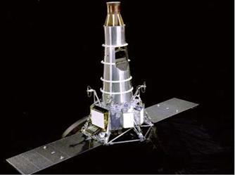
Fig. 10.1 The Ranger. Courtesy of NASA

The Ranger Program was NASA’s first step in achieving President Kennedy’s goal of landing a man on the Moon and returning him safely by the end of the 1960s. This long forgotten lunar probe program was initially a source of embarrassment to NASA and the nation, but eventually achieved its goals and paved the way for the Surveyor Program, followed then by the Apollo triumphs. The Ranger spacecraft mission evolved into a simple task: to take images of the lunar surface and return those images to Earth by a telemetry link until the Ranger spacecraft smashed into the Moon.

The Ranger Series

The Ranger Series

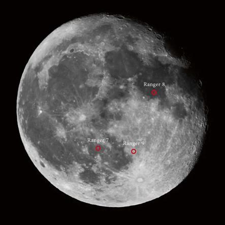
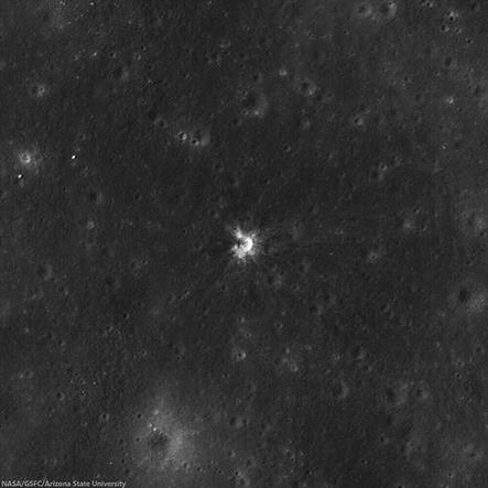
Fig. 10.3 LRO photo of the Ranger impact sites. Photo courtesy of NASA and Arizona State University

In the scope of this book, consider visually locating the Ranger sites with a telescope as extra credit. LRO photos have located the Ranger impact sites with difficulty. Fortunately, the Apollo 12 landing site is not only within walking dis­tance of Surveyor 3, but is also within the general area of the Ranger 7 impact zone. Apollo 11 also landed in the general vicinity of Ranger 8. To the backyard observer, basically locating Apollo 11 and Apollo 12 also encompasses the Ranger 7 and Ranger 8 impact zones. To locate the Ranger 9 impact site, first locate the major crater Ptolemy. The crater just south of Ptolemy is the crater Alphonsus, and Ranger 9 impacted just slightly north and east of the central peak within the crater.

The Ranger program was a series of unmanned lunar missions by NASA in the early 1960s whose design goal was to obtain the first close-up images of the lunar surface. The development of the basic Ranger spacecraft system began in 1959. The original concept for Ranger included a gamma ray spectrometer, radar altimeter, television imaging system, and a soft landing seismometer. These scientific equipment should sound familiar as parts of the eventual Apollo sci­entific equipment suites. The first six Ranger missions were complete failures, as NASA went through a learning process for developing space capable vehi­cles, space navigation, and launch technology and procedures. Ranger 1 and 2 were launch failures, and Ranger 3 and 5 totally missed the Moon. Ranger 4 impacted the Moon but experienced electronic systems failure. Ranger 6 impacted the Moon, but its cameras failed to function. At one point, the program was called "shoot and hope". After two congressionally mandated reorganiza­tions of NASA and JPL, the Ranger program was stripped of much of its scien­tific equipment and simplified to its final kamikaze space camera configuration. Ranger 7 successfully returned images in July 1964, followed by two more successful missions.

The Ranger spacecraft had three different configurations.

• Block I, consisting of Ranger 1 and 2, were test missions. They were launched in 1961 for engineering development, and were not targeted for the Moon. The Ranger 1 spacecraft was designed to go into an Earth parking orbit and then into an extended elliptical Earth orbit to test systems and strategies for future lunar missions. Ranger 1 was launched into the Earth parking orbit as planned, but the Agena B booster stage failed to restart to put it into the higher trajectory, so when Ranger 1 separated from the Agena stage it went into a low Earth orbit and began tumbling. The satellite re-entered Earth’s atmosphere on August 30, 1961. The Ranger 2 followed a similar fate, and was launched into a low earth parking orbit, but an inoperative roll gyro prevented the Agena booster stage restart. As with its predecessor, Ranger 2 could not be put into its planned deep-space tra­jectory, and was stranded in low earth orbit upon separation from the Agena stage. The orbit decayed and the spacecraft reentered Earth’s atmosphere on November 20, 1961.

• Block II missions comprising of Ranger 3, 4, and 5, were launched during 1962 to achieve rough lunar landings, obtain science data, and test approach television camera operations. These Ranger spacecraft experienced satisfactory vehicle performance, but Ranger 3 missed the Moon by approximately 23,000 miles and Ranger 5 missed the Moon by about 450 miles. Ranger 4 suffered electronics problems that caused the solar panels to not open. Ranger 4 battery power failed after 10 hours and the probe was unable to perform mid-course corrections or activate its cameras. Ranger 4 impacted the Moon on the far side.

• Block III Missions were the Ranger 6, 7, 8, and 9 which used the experience of the earlier Ranger missions to achieve success in 1964 and 1965. NASA learned its lessons on navigating to the Moon and made technology modifications to enable transmission of high-resolution photographs of the lunar surface during the final minutes of flight. Ranger 6 performed satisfactorily en route to the Moon, but the camera failed to operate before lunar impact. Success finally came with Ranger 7, 8, and 9, as those missions fulfilled NASA objectives and provided more than 17,000 photographs at resolutions higher than ever achieved. The Ranger 7 and 8 missions provided coverage of the two types of mare terrain that included the area of the eventual Apollo 11 landing site. Ranger 9 provided coverage of the highland region, impacting in the large central highland crater Alphonsus.

The Ranger photographs provided valuable photographic information for future landing site selection for Surveyor and Apollo missions, and provided surface detail unavailable from Earth-based observations. Each Ranger space­craft had 6 cameras on board. The basic cameras were the same with each camera set up for different exposure times, fields of view, lenses, and scan rates. The camera system was divided into two channels, P for partial and F for full, with each channel design having with independent power supplies, timers, and transmitters.

• The F-channel had 2 cameras: the wide-angle A-camera and the narrow angle B-camera. The final F-channel image was taken between 2.5 and 5 seconds before impact at an altitude of approximately 10,000 feet.

• The P-channel had four cameras: P1 and P2 (narrow angle) and P3 and P4 (wide angle). The last P-channel image was taken between 0.2 and 0.4 second before impact at an altitude of approximately 2,000 feet.

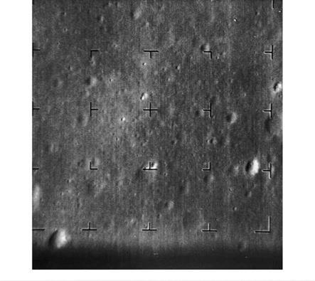
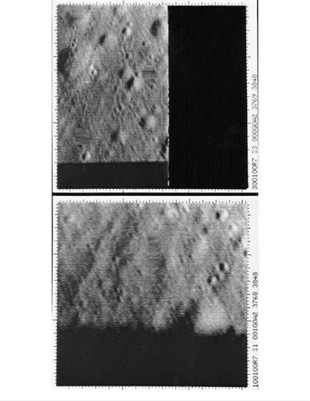
The images provided better resolution than was available from Earth based views by a factor of 1000. The smallest crater that earthbound telescopes could achieve was about the size of a large NFL or major college football stadium, while the images produced by the Ranger cameras showed from pickup truck sized cra­ters down to the 1 feet sized features in Ranger 9 photos. These high resolution images showed Apollo mission planners that finding a smooth landing site was not going to be easy.

The Ranger Series

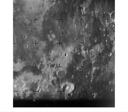
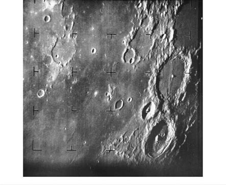
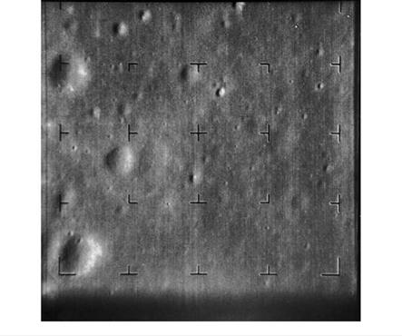
Fig. 10.4 Photo Sequence taken by Ranger 7 a camera approaching the Moon. Courtesy ofNASA

The Ranger Series

Fig. 10.5 Courtesy of NASA

The Ranger Series

The Ranger Series

The Ranger Series

Fig. 10.8 Photo Sequence taken by Ranger 7 p camera approaching the Moon. Courtesy ofNASA

The Ranger Series

Fig. 10.9 Courtesy of NASA

Impact on Society and Culture

To the post World War 2 generation, the Apollo Program represented the hopes and dreams of a bright future and great adventure that was tantalizingly within reach. But the main driver for the race to the Moon was international politics. Created during the height of the Cold War, the rivalry between the two great superpowers, the United States and the U. S.S. R,. provided the impetus for the push into space, culminating in the success of the Apollo Program. The technical challenges were great, but the basis of science supported the idea of landing on the Moon. The technical groundwork of physics, chemistry, and engineering had been laid decades before, and the national focus and challenge of accomplishing a manned lunar mis­sion within a decade provided the necessary energy, commitment, and funding to achieve the goal.

The generations following the Apollo triumphs have lost their way in space. The goals of space travel have become muddled. There is no superpower rivalry that is driving nations to race into space and achieve the goal of landing on Mars. There is no international or national imperative that is pressuring mankind to go to Mars, other than curiosity and the need to explore. The society of the common man has lost sight of the benefits attained by striving towards a common, far reaching goal. The focus on immediate financial accountability has fogged mankind’s vision of the future.

A manned mission to Mars benefits man’s need for exploration, knowledge, and adventure. On the practical side, a program to launch a manned mission to Mars, or even a return to the Moon for potential colonization, represents an opportunity for job creation. New jobs are created from programs directly supporting the space effort to spinoff industries that apply new technologies which provide beneficial products and services. A forward looking approach to space will benefit better edu­cation for the populace, more employment, and better and more meaningful jobs.

Rose colored glasses? Maybe. But the evidence shows the benefits of space – related research and development in a trickle down transfer to every day use.

Every year, NASA publishes a book entitled Spinoff, which highlights products and industries created as off-shoots from space technology. Examples from a recent issue of Spinoff listed the following recent NASA-derived technologies transferred to everyday use:

• Spacesuits incorporating sun-blocking fabric have been adapted to clothing offering protection to ordinary beach goers and people with light sensitivities.

• Gravity-loading technology designed to help astronauts exercise in space have been incorporated into anti-gravity treadmills for rehabilitating after surgery.

• A device NASA invented to study cell growth in simulated weightlessness has been applied to medical research into treatments for heart disease, diabetes, and cirrhosis.

• A star mapping algorithm developed for the Hubble telescope has been adapted to identify unique migrational patterns of endangered species.

• NASA research and development into materials and manufacturing techniques are bringing carbon nanotubes into greater use in everyday applications, such as nanofiber filters to eliminate contaminants.

• Thermal insulation technologies developed for isolating the cryogenic tempera­tures of Saturn V and Space Shuttle fuel tanks have been transferred to applica­tions in the home, resulting in thermal insulation strips that easily apply to wall studs, providing an affordable and environmentally friendly boost to a home’s insulation factor.

These are just a handful of thousands of products derived from the research and development of the space programs such as Apollo, the Space Shuttle, and the ISS. Many new innovations and breakthroughs in technology will result from a focused effort to land a manned mission on Mars. And the public ultimately benefits from these discoveries and innovations in everyday life.

Lunar Photography

Many of the non-NASA lunar photos in this book were taken by the author. The equipment used was selected to reflect typical sized telescopes owned by a majority of backyard observers. 80 mm to 130 mm refractors on equatorial mounts were utilized, with a digital single-lens reflex (DSLR) camera. The majority of the author’s photos were taken using a 102 mm Stellarvue 102ED mounted on a Celestron CG-4 equatorial mount, with a few photos from a 130 mm aperture Brandon refractor mounted on a computer-driven Vixen equatorial mount. A Canon Rebel XTi DSLR camera was used with either the prime focus technique or Barlow projection technique with a Proxima 1.5x Barlow, in combination with various camera-to-telescope adaptors. The goal was to present the reader a view of the Moon through a typical hobbyist’s telescope at low and medium magnifications.

The reader will notice that many of the photos were taken when the Moon was not full. The Moon, being a three-dimensional object, casts beautiful shadows dur­ing its less-than-full phases. The full Moon tends to be drab and two dimensional, both in photographs and with the naked eye peering through the eyepiece of a telescope, because the fully illuminated surface casts no shadows. So, for eye appeal and the logical fact that there are more days that the Moon is not in its full phase, many of the locator photographs in this book were taken during the first quarter and gibbous phases of the Moon.

Site Selection

From the standpoint of the Apollo program, NASA planners desired an initial target area to be one of typical mare and near the lunar equator. The selected region was a relatively detached sea between Ocean of Storms and Sea of Clouds, bounded by the Riphean Mountains on one side and the bright cratered area containing Guericke Crater and Parry-Bonpland Crater on the other.

Mission Description

Launch: July 28, 1964. Impacted Moon: July 31, 1964, at 13:25:49 UT. Landing Site: Mare Cognitum (The Sea that has Become Known), 10.35°S lat., 339.42°E long.

The mission objective of Ranger 7 was carried out flawlessly by obtaining close – up pictures of the lunar surface for the benefit of both the scientific community and the Apollo program planning. Ranger 7 transmitted approximately 4,000 television pictures of the target area before smashing itself in the lunar surface. The signals from the six television cameras aboard the spacecraft were transmitted during the last 17 minutes of the flight. The picture taking spanned a distance range from slightly more than 1,800 miles to approximately 500 yards above the surface.

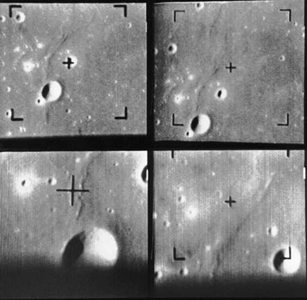
Fig. 10.12 Photo Sequence taken by Ranger 8 p camera approaching the Moon. Courtesy of NASA

•ОцЦрМИЙі

Site Selection

The basic objective in selecting the Ranger 8 impact site was to choose an area which, in conjunction with the Ranger 7 photographs, would provide a more com­plete knowledge of the lunar maria within the Moon’s equatorial zone. Applying the newly evolving Apollo constraints, a point near the equator and 15° from the termi­nator was chosen.

Robotic Exploration Versus Manned Exploration

A decades long debate has existed over the merits of robotic exploration, using deep space probes and landing robotic rovers, instead of manned missions.

Supporters of manned missions have cited the large and ever increasing numbers of scientific papers based on data generated from the Apollo mission in the four

decades since Apollo Moon landings. The area covered by the astronauts, onsite human judgement for sampling or executing experiments, and the efficiencies and problem solving of manned exploration are often cited as advantages.

Robotic exploration is less expensive and more resource efficient. When the kind of resources necessary to accomplish a manned Mars mission, dozens of robotic missions can be planned and accomplished for robotic exploration of a good part of the Solar System, including the large major planets and visiting comets and asteroids. Without the burden and risks of keeping astronauts alive in space, robotic exploration does not need advanced propulsion to lessen the transit time, heavy and cumbersome shielding from radiation, or life support systems. As is done now, planetary gravity assisted deep space probes can take years to arrive at their solar system goals and accomplish their missions.

The drawback to robotic exploration are twofold. One is the risk of equipment failure that is difficult to correct in-flight. The Jupiter probe Galileo is a prime example. After its launch, the main antenna failed to fully deploy. Despite repeated attempts to dislodge and free 3 of the 18 antenna ribs, the main antenna never was fully functional. Fortunately, a secondary low-gain antenna was used in the main antennas place to transmit data, but at a reduced bandwidth. The lower bandwidth resulted in slower transmission speed, and only 70 % of the Galileo scientific goals being met.

The second drawback is that a robotic mission does not capture the imagina­tion of mankind. Great accomplishments and discoveries have result from robotic missions, but the lack of a human presence does not produce the public excite­ment. People don’t remember where they were when Surveyor 1 landed on the Moon, but people remember where they were and how they felt when Apollo 11 landed and Neil Armstrong took his first step on the lunar surface. Robotic mis­sions do not produce the same exhilaration of the human spirit as manned explo­ration does.

A possible alternative that is the hybrid of both types of exploration is a manned mission to Mars orbit, with the deployment of a robot astronaut remotely controlled from the manned Mars spacecraft in orbit. A human astronaut would have realtime control capability of a robot astronaut on the Martian surface for exploration and experimentation.

One of the current problems of controlling Mars rovers, such as Curiosity, Spirit, or Opportunity, is the 5-20 minutes command latency because of the distance from Earth to Mars. A manned spacecraft orbiting Mars can launch a robot astronaut for landing on the Martian surface and provide realtime or near-realtime control. Greater selectivity of samples and human-like dexterity can be designed into a robot astronaut. New robotic technology can provide a remote controlled human analog on the surface of Mars without the risks of exposing humans to the chal­lenges of landing on, surviving the Martian environment, exploring, and lifting off the surface of Mars. A large cost savings can result by removing the technological challenge of landing on and taking off the surface of Mars. Multiple robot astro­nauts could be deployed over different areas of Mars during the same mission, achieving greater coverage of the planet. Multiple deployment maximizes the mission effectiveness, and maximizes the cost efficiency of the mission. The robot astronaut can be switched off at mission’s end, and possibly used in future mis­sions – more bang for the buck. No life support concerns would be incurred on the Martian surface. The risk to human life, and overall mission risk would be lessened with this type of hybrid mission, while providing greater control of experiments and Martian sampling than currently available with Mars rovers. A simpler, more cost effective, more efficient, and less risky manned Mars mission may be achieved with this type of hybrid man-machine approach.

NASA Apollo, Lunar Reconnaissance Orbiter, and Other Lunar Probes

The structure of this book was developed to allow the reader to proceed from pic­ture to picture on a zoom-in journey: locating the Apollo landings on the Moon from a naked eye or binocular point-of-view, to a telescope view, then transition to NASA photos of the landing sites, to finally photos from each landing taken by the Apollo astronauts during their missions. NASA has thousands of lunar photos, of which many are indelibly imprinted in the public’s mind. Rather than repeated the familiar, many of the NASA photos chosen for this book for comparison to the Lunar Reconnaissance Orbiter, or LRO, photos.

The genesis of this book stems from the Lunar Reconnaissance Orbiter (LRO) photos first released to the public in 2009. Among the LRO photos were the over­head images of the Apollo landing sites, with amazing details of the Lunar Module (LM) descent stage, trails left by the astronauts walking or using the Lunar Roving Vehicle (LRV), and experiments left on the Moon’s surface. Seeing these LRO photos recapture for many people the memories and excitement of the Golden Age of NASA.

In researching for this book, the author was reminded of the unmanned lunar missions that preceded Apollo: the first and long forgotten photographic probe

Ranger series, and the lunar landing Surveyor. These early attempts by NASA, first to impact the Moon with Ranger, and then to accomplish lunar landings with Surveyor, were clearly a scientific and engineering learning experience. The first six Ranger missions were punctuated by failures in equipment and technique. Ranger 1 and 2 experienced launch failures. Ranger 3 and 5 missed the Moon entirely, while Ranger 4 and 6 impacted the Moon but failed to relay any data back to NASA. It wasn’t until Ranger 7, 8, and 9 that the NASA mission goals were accomplished by relaying photographic data prior to impacting the Moon.

The Surveyor program had its own share of problems, with Surveyor 2 and 4 crashing and Surveyor 3 having unplanned launches from the Moon’s surface due to the vernier rockets continuing to fire. Again, the lessons learned from the early Surveyor missions enabled NASA to successfully complete Surveyor 5, 6, and 7 missions.