Category Mig

MiG-3 with AM-38 Engine

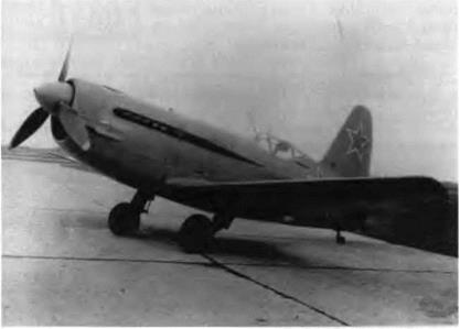
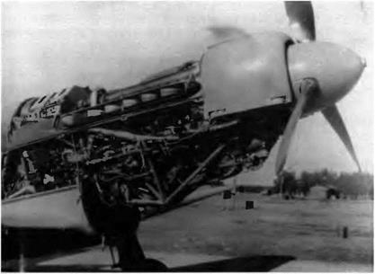
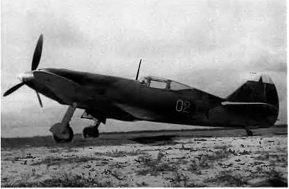
In an attempt to correct the inadequacy of the MiG-3 at low and medi­um altitudes, the AM-35A was replaced by the AM-38, the only avail­able engine that could give the aircraft the means to stand up to the Messerschmitt Bf 109Fs first encountered in June 1941. Installing the AM-38 in the MiG-3 required few modifications, since the weight and overall dimensions of both engines were almost identical. The AM-38 afforded 1,178 kW (1,600 ch) at takeoff, and its maximum rating at

2,0 m (6,560 feet) was 1,141 kW (1,550 ch).

A production MiG-3 was reengined in this way and somewhat mod­ified by reshaping the exhaust pipes, removing the bomb racks, and suppressing the inert-gases transfer system. The aircraft was ready at the end of July 1941, and it went up for its maiden flight at the begin­ning of August with an LII pilot, Yu. K. Stankevich. The flight test pro­gram was carried out by Nil VVS pilots A. G. Kochetkov, A. G. Kubishkin, and A. M. Popyelnushenko as well as LII pilots such as G. M. Shiyanov and A. V. Yumashev Tests ended on 17 August. They showed that the reengined fighter was a sound machine if flown in ambient temperatures lower than 16-20° C (61-68° F), but the engine cooling system had to be modified for use in higher temperatures. The

image32

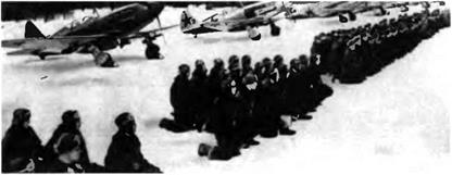
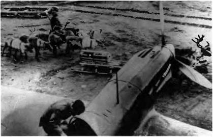
An anachronistic scene: supplies were delivered on this MiG-3 airbase on sleds pulled by reindeer.

test report concluded, "Below 4,000 m [13,100 feet], the АМ-38-engined MiG-3 offers new tactical possibilities and can successfully face the enemy fighters at low and medium altitudes." The time required for a 360-degree turn had dropped to between twenty and twenty-one sec­onds. Considering this laudatory appraisal, series production of the air­craft was recommended. But this plan too was thwarted by the unavail­ability of the AM-38 engine, which was still reserved for the 11-2 assem­bly lines. However, a repair workshop fitted a small number of MiG-3s with overhauled AM-38s because no more AM-35As could be found. Some of these MiG-3s were equipped with two synchronized 20-mm ShVAK cannons (100 rounds each) to fight in PVO units.

Specifications

Span, 10.2 m (33 ft 5.6 in); length, 8.25 m (27 ft 0.8 in); height in level flight position, 3.325 m (10 ft 10.9 in); wheel track, 2.78 m (9 ft 1.4 in); wing area, 17.44 m2 (187.72 sq ft); empty weight, 2,582 kg (5,692 lb); takeoff weight, 3,225 kg (7,110 lb); fuel, 463 kg (1,020 lb); oil, 45 kg (99 lb); wing loading, 185 kg/m2 (37.9 lb/sq ft).
Performance

Max speed, 587 km/h at 3,000 m (317 kt at 9,800 ft); 592 km/h at

4,0 m (320 kt at 13,000 ft); max speed at sea level, 547 km/h (295 kt); climb to 5,000 m (16,400 ft) in 7.95 min; service ceiling, 9,500 m (31,200 ft); takeoff roll, 380 m (1,250 ft); landing roll, 400 m (1,310 ft).
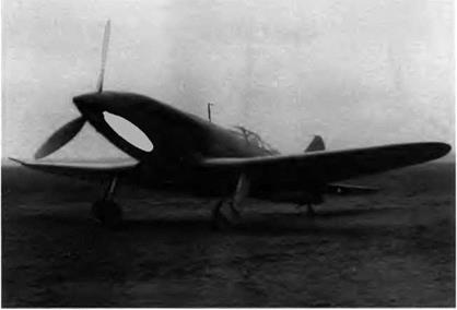
image33

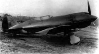
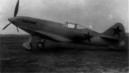
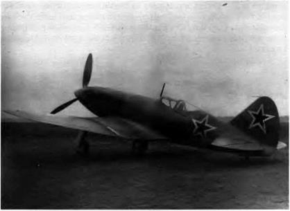
The ОКБ tried to prolong the life of the MiG-3 at all costs, but matching a radial engine with an airframe engineered for an in-line engine raised too many difficulties.
MiG-Я Series

1-300 / r

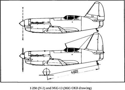
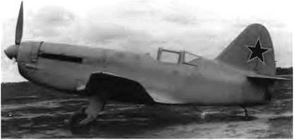
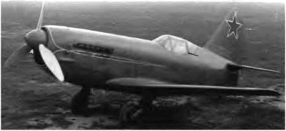
At the end of World War II several OKBs —including MiG—were assigned to design fighters powered by a turbojet engine MiG had the advantage of experience with its 1-250 But above 900 km/h (486 kt) it

image80

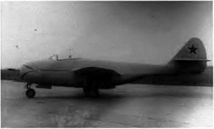
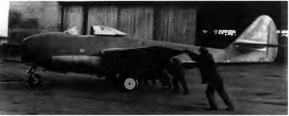
The 1-300 or izdeliye F, prototype of the MiG-9, was the first Soviet jet aircraft to fly— less than three hours before the Yak-15.

was obvious that the technology of this aircraft’s combined power plant was completely outdated. And at that time there was not a single homemade jet engine available in the USSR, since all research pro­grams in this field were postponed because of the war. The Soviets had to make do with the few jets recovered either in eastern Prussia or in Germany itself. Near the end of the war one of the factories that made BMW 003 and Junkers Jumo 004 jet engines fell into the hands of Sovi­et troops. It was then decided to mass-produce them in the USSR. After a close examination of each type the OKB engineers chose the BMW 003, which delivered 784 daN (800 kg st) and 1,568 daN (1,600 kg st) in a twin-jet configuration. A. G. Brunov was named the chief project engineer. In the first preliminary design the future F fighter had two underwing engines like the Messerschmitt Me-262, the Gloster Meteor, and the Sukhoi Su-9, which complied with the same specifications and was first flown in August 1946.

One of Mikoyan’s students, the well-known aeronautical expert A. V. Minayev, wrote in Aircraft of the USSR:

When Mikoyan started working on his fighter project, a lot of spadework had already been done as regards high-speed aerody­namics, aircraft aerodynamic configurations, and aeroelasticity. The more I go into this period, the more I am amazed at discov­ering the huge amount of R&D conducted during the war. No Soviet jet aircraft could have flown in 1946 without all this research work, which was all the more valuable to us because it was original and homemade.

image81

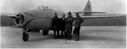
Left to right, in front of the F-l, the first prototype of the 1-300: A. Karyev, test engineer; G. Buchtinov, trainee mechanic; A. Grinchik, test pilot (he was killed while flying the F-l), and V. Pimyenov, field mechanic.

The preliminary designs for the project were highlighted by an innovative proposal made by Mikoyan: to place both jets side by side into the fuselage. With such an arrangement the wing remained aero – dynamically clean, drag was reduced, and maneuverability improved, particularly in the event of engine failure. The preliminary design was approved in the late fall of 1945. A full-scale mock-up was built, and manufacture of the parts and systems was launched. After approval of the mock-up in January 1946 the Narkomaviaprom issued decree no. 157, assigning to the MiG OKB the task of building and flight-testing the aircraft.

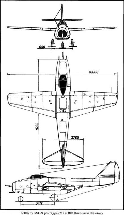
The 1-300, coded F at the OKB, was an all-metal midwing single- seater with a front air intake to feed the two jet engines. The two-spar straight wing had a TsAGI-1 series profile, a constant thickness ratio of 9 percent, slotted flaps, and Frise ailerons. The lower part of the rear fuselage was protected against the high-temperature exhaust gases by a heat shield (a 15-mm-thic. k air-gap sandwich of stainless steel plates with a corrugated core). The cantilever horizontal tail was set high on the fin to stay dear of the exhaust flow. Flying controls were standard; the stick rod-operated, the rudder pedals cable-operated. The cockpit was not pressurized.

The fuel system comprised four fuselage and six wing tanks having a total capacity of 1,635 1 (432 US gallons). The engines ran on T-2 kerosene—a fuel commonly used in tractor engines—because aviation kerosene was not yet available. Each BMW 003 was fitted with a Ridel

image82

image83

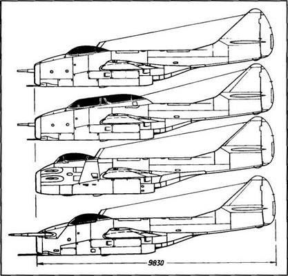
Top to bottom: 1-301 (FS), 1-301T (FT), МЮ-9М (FR), and 1-302 (FL)

(MiG OKB drawing)

combustion starter that ran on aviation gasoline. The armament of the prototype consisted of one 57-mm N-57 (100P) cannon in the air intake splitting wall and two 23-mm NS-23 (115Р) cannons with 80 rpg at the bottom of the air intake. This arrangement was to prove somewhat troublesome, as will be explained later. The N-57 was eventually replaced with a 37-mm N-37 with forty rounds.

For the first time, a Soviet fighter was fitted with a tricycle landing gear. The legs and wheels of the main gear retracted outward into wing wells. The castor front wheel retracted backward into the fuselage and was fitted with a hydraulic shimmy-damper. All of the landing gear had levered suspension with lower arms trailing the wheel.

On 6 March 1946 the prototype was rolled out and entrusted to the care of the factory flight-testing team. All systems were checked, the aircraft was weighed without and with fuel, and its engines were run up. No one actually knew the BMW 003’s time between overhauls, so a hypothetical ten-hour TBO was adopted. On 23 March the aircraft was

Extract from Flight Log No. 19, 24 April 1946

Aircraft

Flight

Takeoff/landing

Flight

Test

type

Pilot

no.

time

time

engineers

1-300 (MiG-9)

A N Grinchik

425

1112/1118

6 min

Poyarkov, Karyev

Yak-(3>15

M. I. Ivanov

424

1356 1401

5 min

Konukov, Filippov

Source LII central archives.

moved to the Ramenskoye airfield. Meanwhile, several airframes were stressed during static tests; they were progressively overloaded until they ruptured in order to determine their strength.

An experienced LII pilot, Aleksei Nikolayevich Grinchik (nick­named Lesha), was put in charge of the flight tests of the 1-300 (F). In 1941-42 he flew sixty-two missions in a MiG-3 (later he flew an LaGG-3) and fought on the Kalinin front. He was wounded in the leg during a dogfight and forced to make a pancake landing. When he was released from the hospital he was appointed deputy director of flight tests at the LII. In the spring of 1946 there were no more than eleven first-class test pilots in the USSR; Grinchik was the youngest but probably the most experienced. Before the war he was a student at the Moscow Avi­ation Institute (MAI). When the war ended he joined the TsAGI to add to his knowledge. The flight-test team also included chief engineer A. Karyev and two field mechanics, V V. Pimyenov and G Bushtinov.

On 12 April 1946 Grinchik made the first ground rolls, and three days later he lifted it a few feet into the air. At more than 900 m (2,950 feet), the takeoff roll proved to be longer than expected. On 19 April the F climbed to 4 m (about 13 feet), and on 24 April it made its true first flight, which lasted twenty minutes. The first Soviet jet aircraft had flown. Three hours later the Yak-15 went up for its maiden flight.[1] The USSR’s jet era was under way.

The second flight took place on 7 May 1946, and the third flight on the eleventh. Not until the eighth flight was severe buffet noticed around the engines. The next three flights failed to identify their cause and eliminate them. On 5 June an emergency meeting was called in Mikoyan’s office to analyze the problem. After listening to the pilot and examining the flight-test data, well-known scientist M. V. Keldish pro­posed that the present layout of the aircraft be abandoned and the engines relocated either above or underneath the wings. He thought that the vibrations were caused by the stepping of the fuselage behind the engines. But during the twelfth flight on 7 July, after the heat shield was strengthened, the vibrations vanished inexplicably and test flights were finally resumed. Tragically, during the nineteenth flight four days later Grinchik was fatally wounded while giving a flight demonstration for a group of WS officers. The wing-to-body fairing broke off in flight, smashing the horizontal tail to pieces, and the aircraft crashed. This first 1-300, the F-l, had spent a total of six hours and twenty-three min­utes in the air.

Two more prototypes, the F-2 and F-3, were assembled quickly in the experimental workshop The F-3 was flown for the first time by LII pilot M. L. Gallai on 9 August 1946, and the F-2 followed with G M. Shiyanov at the controls two days later. On 18 August Shiyanov led a flyover in this prototype during the air force day cele­brations at Tushino.

By 28 October all of the following GK Nil WS pilots had flown the 1-300: A. G. Proshakov, A. M. Kripkov, A. G. Kubishkin, Yu. A. Antipov, and G A. Sedov (who is today chief constructor at the MiG OKB). The aircraft’s joint tests (factory tests plus state acceptance trials) got under way on 26 October, leading to certification During the state trials, over two hundred aerobatics were performed—including the first spin ever attempted by a jet aircraft—without a single engine failure. The certifi­cation document contained the following statement: "Its handling char­acteristics have made this aircraft, on the whole, easy and pleasant to fly. Its controls are not binding and it is not hard to get accustomed to this machine.” Mass production was consequently recommended and launched immediately. The aircraft entered service in the WS with the service designation of MiG-9.

Specifications

Span, 10 m (32 ft 9 7 in); length, 9.75 m (31 ft 11 8 in); height, 3.225 m (10 ft 6.7 in); wheel track, 1.95 m (6 ft 4.8 in); wheel base, 3.072 m (10 ft 0.9 in); wing area, 18 2 m2 (195 9 sq ft); empty weight, 3,283 kg (7,236 lb); takeoff weight, 4,860 kg (10,710 lb); fuel, 1,334 kg (2,940 lb); oil, 35 kg (77 lb); wing loading, 267 kg/m2 (54 .7 lb/sq ft); max operat­ing limit load factor, 6.

Performance

Max speed, 910 km/h at 4,500 m (491 kt at 14,760 ft), max speed at sea level, 864 km/h (467 kt), climb to 5,000 m (16,400 ft) in 4.5 min; to 10,000 m (32,800 ft) in 14.3 min; service ceiling, 13,000 m (42,640 ft); landing speed, 170 km/h (92 kt); range, 800 km (497 mi); takeoff roll, 910 m (2,985 ft); landing roll, 735 m (2,410 ft); rate of turn, 9.73°/sec.

image84

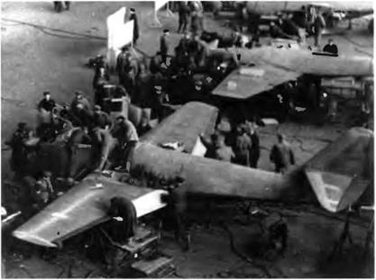
The first ten MiG-9s had to be delivered within seventy days; they were delivered in only fifty-five days This explains the feverish activity in this assembly shop.

image85

Rollout—by hand—of the premier MiG-9. The first ten aircraft were identical to the

prototype.

MiG 3 with IV» 82 Engine /1210 / IKh

When series production of the MiG-3 stopped in December 1941 for lack of engines, the Perm power plant factory was producing the M – 82A, a 14-cylinder, double-row, air-cooled radial engine. Its power out­put was high at takeoff—1,251 kW (1,700 ch)—but it lost power rapidly with altitude. At 6,500 m (21,300 feet) its rating dropped to only 979 kW (1,330 ch)

Despite this shortcoming the MiG OKB redesigned the MiG-3 with an M-82 engine in a risky attempt to prolong the aircraft’s life. Chief engineer I. G. Lazarev tried to match the engine with the front fuselage structure with a minimum of modifications and designed an engine cowling to minimize load losses resulting from its internal turbulent flow.

The cockpit canopy was enlarged and deepened to improve rear and lateral visibility. The fin area was increased slightly to improve yaw stability, and the wing was fitted with leading-edge slats tested on a production MiG-3. The three 12.7-mm UBS machine guns (one on top of the engine cowling and one on each side of it) were controlled by a single trigger.

Five I-210s were completed in November-December 1941, and the first flight took place in December with Nil WS pilot V. Ye. Golofastov in the cockpit. From the very beginning of the test flights, strong vibra­tions occurred in the tail unit, and the aircraft’s maneuverability

image34

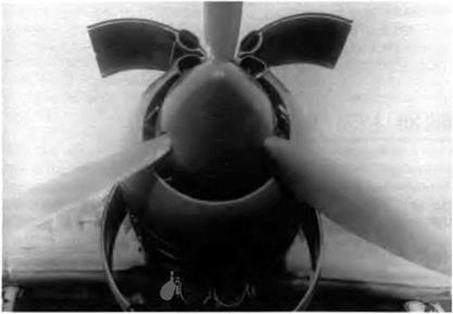
The M-82A was easy to service thanks to the four hinged access panels of the engine cowl.


image35

proved to be rather scanty. The size of the engine master cross section and the poor airtightness of the engine cowling generated vortex flows that increased the drag significantly. Despite the high power of the M – 82, the maximum speed of the 1-210 was less than that of the MiG-3 with an AM-35A engine

The aircraft was tested in a TsAGI full-scale wind tunnel and returned to the OKB for modifications. The wind tunnel tests con­firmed the decisive effect of the lack of cowling airtightness on the air­craft’s aerodynamic drag. They led at last to the design of a new aircraft code-named Ye and powered by a M-82F, which was not completed before the end of 1942. Despite its poor performance, the 1-210 was combat-proven on thb Kalinin front. Two 7.62-mm ShKAS synchro­nized machine guns were added to the basic armament.

In some OKB documents the 1-210 is referred to as the MiG-9 (the first of many).

Specifications

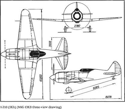
Span, 10.2 m (33 ft 5.6 in); length, 8.078 m (26 ft 6 in); wheel track, 2.78 m (9 ft 1.4 in); wheel base, 5.022 m (16 ft 5.7 in); wing area, 17.44 m2 (187.7 sq ft); empty weight, 2,720 kg (5,995 lb); takeoff weight, 3,382 kg (7,454 lb), fuel + oil, 360 kg (795 lb); wing loading, 193 9 kg/m2 (39.71 Ib/sq ft)

Performance

Max speed, 565 km/h at 6,150 m (305 kt at 20,170 ft); max speed at sea level, 475 km/h (257 kt); landing speed, 146 km/h (79 kt); climb to

5,0 m (16,400 ft) in 6.7 min; range, 1,070 km (665 mi); takeoff roll, 410 m (1,345 ft); landing roll, 535 m (1,755 ft).

MiG-311 /1230 / D

The aims of this program were not very different from those of the previous designs—that is, improving the aerodynamics, handling quali­ties, and production processes of the MiG-3 even though its assembly lines were now closed. The motivation of this new attempt was to give the MiG-3 a successor without departing too much from the original design.

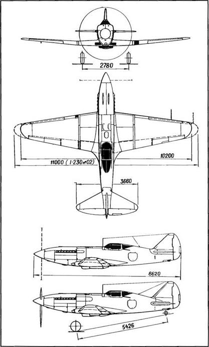
Compared to the MiG-3, the 1-230’s fuselage was 370 mm (14 57 inches) longer. The main landing gear was modified and equipped with more efficient and reliable shock absorbers, and the pilot’s view was greatly improved. Aware of the scarcity of light alloys in 1942, the designers called for the fuselage to be made entirely of wood except at the engine mounting

image36

The 1-230 would have entered mass production, but the engine was not available. Pro­totype no 01 had no antenna mast.

At the time of the preliminary design, the utmost was done so that the 1-230 might be manufactured on the same assembly lines as the MiG-3, with the same production tooling and methods. The quality of the skin finishing and the aerodynamic cleanness of the airframe were superb The aircraft was really a beauty.

The ventral radiator bath underneath the wing center section was moved forward and made much smaller. A slightly bigger wing was used on an experimental basis to increase the aircraft’s ceiling by 500 m (1,640 feet). But this was not considered enough of an improvement to justify acceptance of the new wing.

The team in charge of this program ran into an old snag. The AM- 35A, the only suitable engine for this type of aircraft, was no longer being produced. The AM-38F was certainly not the ideal engine for a fighter—and besides, its entire production run was reserved for the 11-2. Consequently, the 1-230 was fitted with a salvaged AM-35A. The flight reports filed by MiG-3 pilots were taken into account: firepower was increased by mounting two synchronized 20-mm ShVAK (SP-20) can­nons on top of the engine (150 rpg) The 1-230 became the first single­engine MiG equipped with cannons.

The aircraft was first flown and flight-tested in August 1942. Even though the results were positive, there was uncertainty in 1943 over whether series production could he launched. After the prototype roll­out, five preproduction aircraft were completed in the ОКБ workshop and delivered to the 1 GvIAP (1st Guards fighter aviation regiment) for

image37

1-230 (D)/I-231 (2D); bottom, side view of the 1-231 (2D) (MiG OKB four-view drawing)


image38

[-230 prototype no. 02 had a larger wingspan.

combat proving on the Kalinin front, where they performed with dis­tinction. Nonetheless, the chaotic circumstances of most engine manu­facturers in this period (evacuation of production factories, establish­ment of new production facilities in distant places, and difficulties in managerial staff recruitment) made it impossible to resume production of the AM-35A. Despite all its good qualities, the 1-230 did not succeed the MiG-3.

The 1-230 is sometimes called the MiG-3 D (Dalnostniy, long range) or MiG-3U (Ulushchenniy, improved).

Specifications

Span, 10.2 m (33 ft 5.6 in); 1-230 no. 02 span, 11m (36 ft 1 in); length, 8.62 m (28 ft 3.4 in); wheel track, 2.78 m (9 ft 1.4 in); wheel base, 5.426 m (17 ft 9.6 in); wing area, 17.44 m2 (187.7 sq ft); 1-230 no. 02 wing area, 18 m2 (193.75 sq ft); empty weight, 2,612 kg (5,757 lb); takeoff weight, 3,285 kg (7,240 lb); fuel, 324 kg (714 lb); oil, 56 kg (123 lb); wing loading, 188.4/182.5 kg/m2 (38.57/37.36 lb/sq ft); max operating limit load factor, 8.

Performance

Max speed, 660 km/h at 6,000 m (356 kt at 19,680 ft); max speed at sea level, 560 km/h (302 kt); climb to 5,000 m (16,400 ft) in 6.2 min; ser­vice ceiling, 11,500 m (37,700 ft); 1-230 no. 02 service ceiling, 12,000 m (39,360 ft); range, 1,350 km (840 mi).

image39

The 1-231 —as beautiful as the Spitfire—was not the MiG-3’s successor despite its out­standing performance. In 1943 there was not a single factory available to build it.


image40

1-231 / 2D

OKB engineers were desperately tiying to find a successor to the MiG – 3. In 1943 they thought they had hit on something when a new engine, the AM-39 A, became available Its takeoff power reached 1,325 kW (1,800 ch), and it was rated at 1,104 kW (1,500 ch) at 5,850 m (19,190 feet). The engine was installed in an airframe almost similar to that of the 1-230 with the same armament (two 20-mm ShVAK cannons above the engine with 160 rpg).

The 1-231 prototype was completed and test-flown in 1943 with Yu A. Antipov and later P. M. Stefanovskiy at the controls, but it was destroyed as a result of a mislanding. It could have been a chance mishap, the aircraft having shown great capabilities justifying its mass production. But once more a shortage of engines put an end to what would be the final attempt to extend the life of the MiG-3: series pro­duction of the AM-39 had to be stopped a short time after it began. Also, no production unit had the capacity to manufacture the 1-231 They were all busy, day and night, turning out Yakovlev and Lav­ochkin fighters.

Specifications

Span, 10 2 m (33 ft 5 6 in); length, 8.62 m (28 ft 3.4 in); height in level flight position, 3.275 m (10 ft 8 9 in); wheel track, 2.78 m (9 ft 1.4 in); wheel base, 5.426 m (17 ft 9.6 in); wing area, 17.44 m2 (187.7 sq ft); empty weight, 2,583 kg (5,693 lb); takeoff weight, 3,287 kg (7,245 lb); fuel, 333 kg (734 lb); oil, 34 kg (75 lb), wing loading, 188.5 kg/m2 (38 6 Ib/sq ft); max operating limit load factor, 8

Performance

Max speed, 707 km/h at 7,100 m (382 kt at 23,290 ft); climb to 5,000 m (16,400 ft) in 4.5 min, service ceiling, 11,400 m (37,400 ft)

1-211 / Ye

As mentioned earlier, this program was a direct result of the 1-210 tests in one of the full-scale TsAGI wind tunnels. The goal was still to pro­long the MiG-3 series with an updated product. But to improve the level and climbing speeds of the aircraft, it was necessary to find a more powerful engine than the M-82A and to reduce its takeoff weight significantly. The only available engine alternative was the M-82F, delivering 1,362 kW (1,850 ch) at takeoff and 979 kW (1,330 ch) at

image41

image42

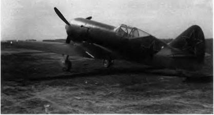
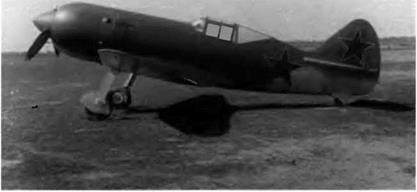
The 1-211 marked a new attempt to match a radial engine with the MiG-3 airframe. This time it was a complete success. But, strangely enough, the project was not pur­sued, and Lavochkin inherited most of the technical innovations tested with this machine.

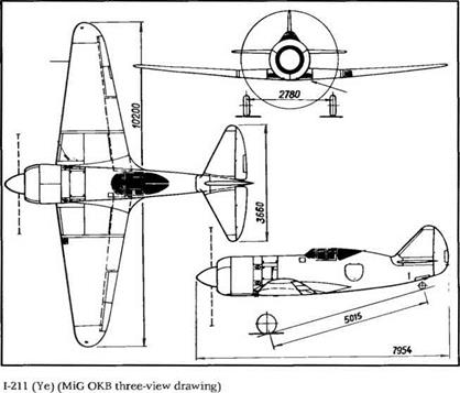
5,400 m (17,700 feet). The 1-211 differed from the 1-210 in several other respects as well. The front fuselage cross section was increased to make the junction of the engine cowling and the fuselage smoother, and the adjustable flaps of the engine exhaust outlet were moved to the sides of the fuselage. The cockpit was moved 245 mm (9.64 inches) back and the fin chord was extended forward, increasing its area and improving the aircraft’s yaw stability. The oil cooler air inlets were moved into the wing root fairings. The shape of the engine cowling was carefully designed to cope with the problem of airtightness and to achieve the best junction possible with the fuselage. All of these modi­fications resulted in an outstanding increase in the aircraft’s speed. In 1942 most of these technical innovations (engine cowling design and airtightness, proper positioning of the engine itself, and the 1-210 wing leading edge slats) were passed on—at the order of the Narkomavprom (state commissariat of the aviation industry)—to the Lavochkin OKB, which adapted them successfully to the La-5, a mass-produced fighter.

The armament was also modified: the 1-210’s machine guns were replaced by two synchronized 20-mm ShVAK cannons at the bottom of engine cowling. Assembly of the 1-211 begai in December 1942 and finished in August 1943. Golofastov was the first pilot to fly it. Two pro­totypes were built, followed by eight preproduction aircraft. The short­comings of the first 1-210 and its engine became nothing more than a bad memory, and the 1-211 proved to be the best Russian fighter of the time. Compared with the 1942 version of the La-5, its level speed was 40 to 166 km/h (21 to 90 kt) higher, depending on the altitude. Com­pared with the 1942 version of the Yak-9, it was 65 to 73 km/h (35 to 39 kt) faster. To climb to 5,000 m (16,400 feet), the La-5 took 1.4 to 2.2 minutes longer, and the Yak-9 0.9 to 1.5 minutes longer. After the pro­totypes passed the factory flight tests, ten preproduction 1-21 Is were delivered to the VVS to prove themselves in combat. They engaged successfully in air battles over the northwestern front near Kalinin. Air force pilots and Nil WS test pilots spoke out in favor of adding the 1-211 to the WS fleet. But in spite of their recommendations and the aircraft’s remarkable flying qualities, the GKO (defense state commit­tee) gave up mass-producing the aircraft because two factories were already building the La-5FN (an La-5 with an ASh-82FN engine)

Specifications

Span, 10.2 m (33 ft 5.6 in); length, 7.954 m (26 ft 1.1 in); height, 3.63 m (11 ft 10.9 in); wheel track, 2.78 m (9 ft 1.4 in); wheel base, 5 015 m (16 ft 5.4 in); wing area, 17.44 m2 (187.7 sq ft); empty weight, 2,528 kg (5,572 lb); takeoff weight, 3,100 kg (6,830 lb); fuel + oil, 385 kg (848 lb); wing loading, 177.75 kg/m2 (36.38 lb/sq ft).

image43

Performance

Max speed, 670 krn/h at 7,000 m (362 kt at 22,960 ft); climb to 5,000 m (16,400 ft) in 4 min; service ceiling, 11,300 m (37,065 ft); range, 1,140 km (710 mi).

PBSh-1 and PBSh-2 Series

PBSh-1

Throughout the 1930s the doctrines relating to the use of big armored units were completely reappraised. Because every new threat demand­ed an immediate answer, a new type of aircraft appeared in the USSR: the shturmovik, or assault aircraft. Several of the best-known aircraft manufacturers worked on this new weapon. At the start of the decade Tupolev proposed two heavy shturmoviks, the ANT-17 and ANT-18, but they were never built. The TsKB (central construction bureau) built four aircraft designed by D. P. Grigorovich, the LSh-1, TSh-1, TSh-

image44

The PBSh-1 main gear was directly inspired by that of the I 200.

2, and ShON. In 1933 a design brigade under the leadership of S. A. Kocherigin—and assisted by the forty-one-year-old M. I. Guryevich, Mikoyan’s future right-hand man—built the TSh-3, also called the TsKB-4. N. N. Polikarpov, for its part, developed the R-ZSh.

All of these attempts led in 1936 to the Ivanov program (“Ivanov” was Stalin’s cable address), an air force initiative that resulted in the construction of such prototypes as the KhAI-5 (R-10) and KhAI-52, designed by Nyeman, winner of the contest; and the ANT-51 and ShB, both designed by Sukhoi. But in the end the true winner was a relative­ly unknown outsider, S. V. Ilyushin. More than 40,000 of its BSh-2s, renamed the 11-2 in 1940, were built because of the war.

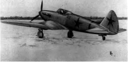
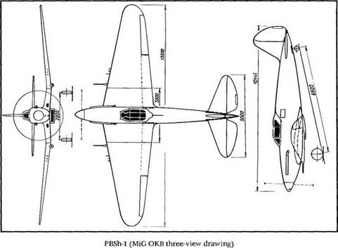
Mikoyan and Guryevich started the preliminary design of their first assault aircraft in 1940. The PBSh-1 (Pushechniy Bronirovaniy Shtur – movik. armored assault aircraft with cannons) was a single-seater designed to attack frontline ground targets such as troops, strong points, and armored vehicles. It had a cantilever inverted gull wing and was to be powered by a 1,178 kW (1,600 ch) Mikulin AM-38 engine. Sensitive parts, the engine, and the cockpit would be protected by armor plating. But the weight of the armor alone was 1,390 kg (3,065 pounds), or 30 percent of the aircraft’s takeoff weight. The design had tc be completely reconsidered to integrate the armor into the stressed structure. It was to be equipped with two 23-mm cannons in fairings beneath the wing (96 rpg) and six 7.62-mm ShKAS machine guns on the wing leading edge (750 rpg). All of these weapons would fire out­side the propeller disc.

image45

image46

The bomber version of the aircraft was to carry in its fuselage either 24 10-kg (22-pound) FAB-10 or 24 8-kg (17.6-pound) FAB-8 bombs and either 280 2.5-kg (5.5-pound) FAB-2.5 or 120 1-kg (2.2-pound) ZAB – 1 bombs. (FAB indicates demolition bombs, while ZAB refers to incen­diary bombs. The number after the acronym reflects the bomb’s weight.) For dive-bombing missions, two FABs ranging in weight from 25 to 250 kg (55 to 550 pounds) could be added beneath the wings.

The preliminary design by N. Z. Matyuk, chief of the aerodynamic design department, was approved on 24 July 1940 by OKO chief engi­neer Mikoyan, his assistant Guryevich, and P. V. Dementyev, manager of Aviakhim factory no. 1. The OKO started work on a full-scale model of the aircraft in the fall. But as soon as the Ilyushin 11-2 was approved for series production, О KB engineers halted all work on the PBSh-1 and started in immediately on the preliminary design for the PBSh-2.

In some OKB documents the PBSh-1 is referred to as the MiG-4.

Specifications

Span, 13.5 m (44 ft 3.5 in); length, 10.145 m (33 ft 3.4 in); height, 3.2 m (10 ft 6 in); wheel track, 2.9 m (9 ft 10 in); wheel base, 6.6 m (21 ft 7.9 in); wing area, 30.5 rrF (328.3 sq ft); takeoff weight, 4,850 kg (10,690 lb); max takeoff weight, 6,024 kg (13,277 lb); wing loading, 159 kg/m2 (32.6 lb/sq ft).

Design Performance

Max speed, 441 km/h at 5,000 m (238 kt at 16,400 ft); max ground speed, 449 km/h (242 kt); range, 900 km (560 mi); service ceiling, 7,600 m (25,690 ft).

PBSh-2

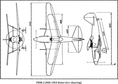
A note came with the PBSh-2 preliminary design created by the factory no. 1 OKO in July 1940. It said: "Considering that hedge-hopping flying in a highly wing-loaded aircraft is rather demanding and moreover that monoplanes seldom forgive pilots’ mistakes at very low altitudes, we have chosen the biplane configuration for the PBSh-2, even though it has been designed to carry out the same missions as the PBSh-1. Biplanes are much easier to fly. They have far better stability and maneuverability."

The PBSh-2 silhouette was quite unusual. Areas of the two wings of this biplane were quite different. The smaller upper wing had a for­ward sweep angle of 12 degrees and no ailerons. A light dihedral was applied to the lower wing outer panels. The whole trailing edge was

image47

The unorthodox PBSh-2 was no more successful than the PBSh-1. The VVS chose instead the Ilyushin shturmovik, the 11-2.

occupied by large ailerons and two-segment flaps. The wings were braced by I-type struts.

Like the PBSh-1, the engine was to be a 1,178 kW (1,600 ch) AM-38 protected (along with the fuel tanks and cockpit) by case-hardening homogenized armor plates whose thickness varied from 7.5 to 15.5 mm. The planned armament was similar to that of the PBSh-1: two 23- mm cannons and six 7.62-mm machine guns.

The center section of the lower wing contained two bays for 1- to 10-kg (2.2- to 22-pound) bombs. As with the PBSh-1, the 25- to 250-kg (65- to 550-pound) bombs were strapped beneath the wings for dive – bombing missions, whatever the diving angle might be. But because 11- 2 production was stepped up at several factories, all work on the PBSh – 2 stopped by the end of 1940.

In some OKB documents the PBSh-2 is referred to as the MiG-6.

Specifications

Span, 8.6/12.4 m (28 ft 2.6 in/40 ft 8.2 in); length, 8.85 m (29 ft 0.4 in); height, 3.5 m (11 ft 5.8 in); wheel track, 2.97 m (9 ft 8.9 in); wheel base, 5.23 m (17 ft 1.9 in); wing area, 10.26/22.14 m2 (110.44/238.3 sq ft); takeoff weight, 4,828 kg (10,641 lb); wing loading, 149 kg/m2 (30.5 lb/sq ft).

Design Performance

Max speed at sea level, 426 km/h (230 kt); range, 740 km (460 mi); range with two 100-1 (26.4-US gal) auxiliary tanks, 929 km (577 mi).

image48

The DIS-200 (T) is sometimes referred to as the DIS 2AM-37 because of its power plant. The engine exhaust pipes extend above the wing’s upper surface.

DIS-200 Series

DIS 200/Т

At the end of the 1930s the VVS could operate a fleet of long-range heavy bombers and tactical medium-range bombers but did not have the escort fighters needed to protect them. As early as 1940, the newly formed design bureau had tackled the development of a long-range escort fighter capable of performing high-speed reconnaissance, light bombing, and torpedoing roles. In the preliminary design it was planned to use new, efficient diesel engines developed by A. D. Charomskii, the M-40 and M-30, which would give the aircraft a much greater range because of their low specific fuel consumption.

But neither of these diesels were as yet reliable, so it was decided to equip the prototype—whose factory code letter was T—with two liq­uid-cooled in-line 1,030 kW (1,400 ch) AM-37s driving three-bladed vari­able-pitch propellers. The exhaust collectors were bent and extended above the wing upper surface. Fuel was distributed into six tanks, four in the wing center section and two behind the cockpit. Two oil coolers were located on each side of the engine cowlings as on the MiG-3. The glycol was cooled by two air scoops placed on each side of the cowl­ings, and the corresponding outlets were located beneath the trailing

image49

The air scoops of the engine coolant radiators on the DIS-200 (T) are on each side of both engine nacelles. The corresponding outlets were placed just under the wing’s trailing edge.

edge of the wing. The engine supercharger inlets were located in the leading edge.

The single-seat, twin-engine T prototype had a low wing, a twin fin configuration, and a structure composed primarily of wood rather than scarce light alloys. The flight tests led to the installation of slats on the wing leading edge. On the trailing edge, to complement the two-seg­ment flaps, high lift was augmented by specially designed ailerons, which could be symmetrically lowered to 20 degrees. The latter feature was a great novelty at the time; today they are known as flaperons. The main gear (950 x 300 tires) retracted into the engine nacelles and the tail wheel into the fuselage, and both were pneumatically operated—a first in the USSR.

The cockpit was equipped for instrument flying, and the pilot had an oxygen dispenser and a radio receiver at his disposal. The sliding aft canopy could be jettisoned. The front, rear, sides, and underside of pilot’s seat were protected by armored plates, and the lower part of the fuselage nose was glazed to give the pilot some downward vision.

The DIS-200 T fighter variant was especially powerful, with one 23- mm VYa cannon in a removable fairing under the nose to complement two 12.7-mm BS and four 7.62-mm ShKAS machine guns on the leading edge of the wing. The cannon fairing could be replaced by a 1,000-kg (2,200-pound) bomb or a torpedo.

The T started its taxiing tests on 15 May 1941 and made its first flight at the end of the month, with A. I. Zhukov at the controls. Flight tests went on all summer at the Khodinka airfield near Moscow and were conducted by Zhukov and V. N. Savkin, an Nil WS test pilot.

image50

Series production of the T was to have taken place at factory no. 1, but the Germans invaded just as the first tests got under way. The air­craft was moved to Kazan, and flight tests were not continued.

In some OKB documents the fighter version is referred to as the MiG-5 and the bomber version as the MiG-2. DIS stands for Dalniy Istrebityel Soprovozhdeniya: long-range escort fighter. The DIS-200 had three competitors: the Tairov Ta-3 (OKO-6bis), the Polikarpov TIS, and the Grushin Gr-1.

Specifications

Span, 15.1 m (49 ft 6.5 in); length, 10.875 m (35 ft 8.1 in); wheel track, 4.6 m (15 ft 1.1 in); wing area, 38.9 m2 (418.7 sq ft); empty weight, 6,140 kg (13,530 lb); takeoff weight, 8,060 kg (17,765 lb); fuel, 1,920 kg (4,230 lb); wing loading, 207.2 kg/m2 (42.4 lb/sq ft).

Performance

Max speed, 610 km/h at 6,800 m (329 kt at 22,300 ft); service ceiling, 10,800 m (35,425 ft); range, 2,280 km (1,415 mi); endurance, 5 h; climb to 5,000 m (16,400 ft) in 5.5 min.

DIS 200 / IT

Because neither Charomskii diesels nor Mikulin AM-37 engines were ready for use, the DIS-200 second prototype was powered by an M-82F, a mass-produced radial engine that could afford 1,250 kW (1,700 ch) at takeoff and 957 kW (1,300 ch) at 6,500 m (21,300 feet). The aircraft – built in Kuybyshev, where factory no. 1 and the OKB had relocated in October 1941 — was first called the IT (factory code).

Both T and IT prototypes had the same structure. The only differ­ence, except for the engines, concerned the heavier armament: four 7.62-mm ShKAS and two 12.7-mm BS machine guns plus two 23-mm VYa-23 cannons. The T could carry either a 1,000-kg (2,200-pound) bomb or a torpedo of the same weight, depending on mission require­ments. The IT rolled out of the factory in January 1942 and made its first flight later that month with G. M. Shiyakov (an LII pilot) at the controls. It was then transferred from Kuybyshev to Kazan, where it was test-flown. Meanwhile, the experience of the war demonstrated that escort missions could be handled successfully by frontal fighters, making the development of a special type of aircraft unnecessary. The IT flight tests were consequently terminated.

image51

DIS-200 (IT) (MiG О KB three-view drawing)

image52

The DIS-200 (IT) or DIS-2M-82F was the second and final prototype of this program. Because long-range escort fighters were no longer needed, flight tests were terminated in 1942.

Specifications

Span, 15.1 m (49 ft 6.5 in); length, 12.14 m (39 ft 9.9 in); height, 3.4 m (11 ft 1.8 in); wheel track, 4.6 m (15 ft 1.1 in); wing area, 38.9 m2 (418.7 sq ft); takeoff weight, 8,000 kg (17,630 lh); fuel, 1,920 kg (4,230 lb); wing loading, 205.7 kg/m2 (42.11 lb/sq ft).

Performance

Max speed, 604 km/h at 5,000 m (326 kt at 16,400 ft); climb to 5,000 m (16,400 ft) in 6.3 min; service ceiling, 9,800 m (32,140 ft); range, 2,500 km (1,550 mi).