Category Mig

MiG-17 / Experimental Versions with Various Equipment and Armament

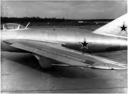
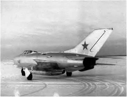
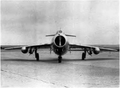
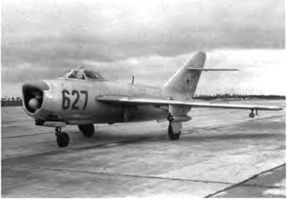
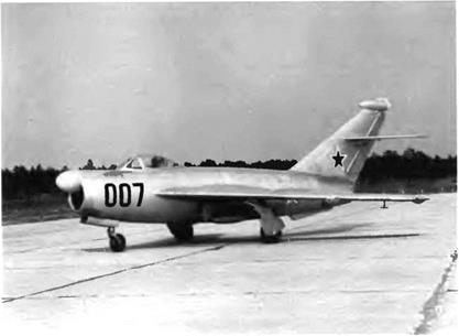
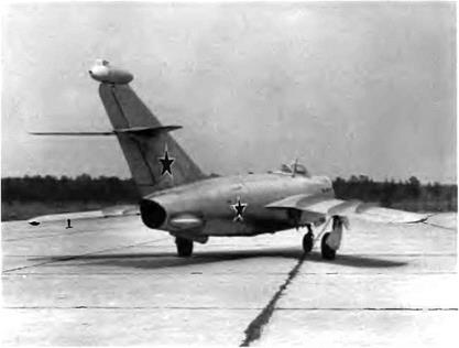
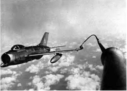
The SP-8, SP-9, SP-11, SI-05, SI-07, SI-16, SI-19, SI-21, SI-21m, and SI – 91 are all MiG-17s equipped with various weapon systems—basically,

image186

This MiG-17 (SI-16) was used to test short-tube rocket pods for eight 57-mm rockets.


This MiG-17 (SI-19) was used to test 190-mm TRS-190 heavy unguided rockets fired from tubes.


image187

image188

This MiG-17 (SP-8) was used to test a new ranging radar dubbed ‘Grad" and housed in this bay in front of the cockpit. Left, the dielectric lip for the antenna

unguided rockets fired from pylons, pods, or tubes. On the SI-16 and SI – 19, for instance, firing experiments were conducted from short rocket pods. The SI-19 was also used for experiments with heavy-caliber TRS – 190 (190 mm) rockets fired from rails or tubes under the wing. Several types of bomb racks were also tested, and much attention was paid to whether the rockets interfered with underslung fuel tanks.

In 1953 the SP-9 was used to test rocket pods attached under long pylons. An automatic ZP-6-Sh device allowed the rockets to be fired one after the other. That prototype had no cannons. A new ranging radar, the Grad (“hail”), was also tested on the SP-8 that year.

The standard MiG-17 gunsight, the ASP-3M, was replaced by an experimental head-up display nicknamed Sneg (“snow”) that displayed the distance from the target and the collimator reticle on the wind­shield front glass panel. Because of development problems, the Grad radar was abandoned and replaced by the Kvant (“quantum"), which passed its tests and was recommended for mass production. All MiG – 175 on the assembly lines were equipped with this new radar, and the equipment was retrofitted on all MiG-17s already in service.

image189

The 1-350 which was supposed to be a frontline supersonic fighter, became a victim of its power plant and was flown only seven times.

MiG 19S / SM 9/3T

The K-13 air-to-air homing missile was developed from a U. S.-built Sidewinder recovered in China, and it was decided to arm all new Sovi­et fighters with this weapon. A modified version of the MiG-19, the SM – 9/3T, was used to test the new missile. Two K-l 3s were attached under an APU-13 launch rail that was itself held by the launch mechanism of the all-purpose pylon. The missile’s fire control system was neutral­ized as long as the gear was not retracted. The tests conducted with the SM-9/3T related to the separation from the APU-13 rail, the perfor­mance of the K-13 immediately after it was fired, and the effects of the missile’s solid-propellant combustion gases on the performance of the aircraft engines.

The SM-9/3T was tested with two K-13s up to Mach 1.245 at 10,800 m (35,400 feet) and up to 910 km/h at 7,600 m (491 kt at 24,900 feet). Those tests showed that the K-13s under the wing had no influence on the aircraft’s handling characteristics. The SM-9/3T was first piloted by A. V. Fedotov on 11 February 1959. Other test flights were made by another OKB pilot, P. M. Ostapyenko, ending on 3 March.

Ye 2A / MiG-23[2]

This lightweight fighter was a direct offspring of the Ye-5—and not, as would appear logical, the Ye-2—but differed from it in the wing and the main gear legs. The delta wing of the Ye-5 was replaced by a sweep – back wing, minus the leading-edge slats of the Ye-2. The upper surface of this wing was fitted with two fences at midspan to play the role of vortex generators in order to increase the ailerons’ effectiveness at great angles of attack. The automatic slats were also discarded because their asymmetrical deployment at times (while sideslipping, for exam­ple) triggered a severe buffet that endangered the aircraft’s pitch and roll stability.

Like the Ye-5, the Ye-2A was powered by the AM-11 turbojet rated for 5,000 daN (5,100 kg st) and was first taken up on 22 March 1956 by G. K. Mosolov. In addition to the prototype, only five other machines were built; yet these were described as "production" aircraft and named

The Ye-2A derived from the Ye-5 more than the Ye-2, but it had a sweepback wing without leading edge slats and was fitted with stall fences on the upper surfaces of the wing (see the side view in the Ye-2 drawing).

MiG-23s even though an assembly line was set up for true mass pro­duction in factory no. 21 as early as 1956. Oddly, the factory tests were carried out with the Ye-2A/6—the fifth "production” aircraft built in fac­tory no. 21—by G. K. Mosolov, V. A. Nefyedov, G A. Sedov, and others The Ye-2A/3 was transferred to the LII MAP for tests of such spe­cial procedures as power-off landings. Six flights made by test pilot A. P. Bogorodskiy proved that those landings did not present any specific problems. But in the meantime the Ye-5 (with the longer fuselage) proved to be the more promising aircraft, and all Ye-2A flight tests were canceled.

Specifications

Span, 8.109 m (26 ft 7.2 in); length (except probe), 13.23 m (43 ft 4.9 in); fuselage length (except cone), 11.33 m (37 ft 2 in); wheel track, 2.679 m (8 ft 9.5 in); wheel base, 4.41 m (14 ft 5.6 in); wing area, 21 m2 (226 sq ft); empty weight, 4,340 kg (9,656 lb); takeoff weight, 6,250 kg (13,775 lb); fuel, 1,450 kg (3,195 lb); wing loading, 297.6 kg/m2 (61 lb/sq ft).

Ye-50A (MiG OKB three-view drawing)

Performance

Max speed, 1,900 km/h (1,026 kt); climb to 10,000 m (32,800 ft) in 7 3 min; service ceding, 18,000 m (59,050 ft); landing speed, 280 km/h (151 kt); range, 2,000 km (1,240 mi).

MiG 2011/lift 50

The MiG-21SMT frontline fighter-interceptor was a cross between the MiG-21M (same airframe, same armament) and the MiG-21MT (same R-13F-300 turbojet, same fuel capacity). The new engine led to modifi­cations of the fuel system and a new setting of the cone control pro­gram. The VHF/UHF communications equipment was improved. The huge dorsal tank proved to be the cause of a major and unfortunate drawback: the aircraft’s yaw stability margin had deteriorated. The capacity of the tank had to be reduced from 900 1 (238 US gallons) to 6001 (159 US gallons), cutting the aircraft’s total fuel capacity to 2,9501 (779 US gallons). The MiG-21SMT’s radar was the RP-22 Sapfir-21, and its armament included a built-in GSh-23L, R-3S/R-3R air-to-air missiles (or R-60/R-60Ms for close combat), and/or UB-16 and UB-32 rocket pods, 240-mm S-24 rockets, and bombs.

The MiG-21SMT was mass-produced in the Gorki factory between 1971 and 1972.

Specifications

Span, 7.154 m (23 ft 5.7 in); fuselage length (except cone), 12.285 m (40 ft 3.7 in); wheel track, 2.787 m (9 ft 1.7 in); wheel base, 4.71 m (15 ft 5.4 in); wing area, 23 m2 (247.6 sq ft); takeoff weight, 8,900 kg (19,615 lb); max takeoff weight, 9,100 kg (20,055 lb); max takeoff weight on rough strip or metal-plank strip, 8,800 kg (19,385 lb); fuel, 2,450 kg (5,400 lb); wing loading, 387-395.7-382.6 kg/m2 (79.3-81.1-78.4 lb/sq ft); max operating limit load factor, 8.5.

Performance

Max speed, 2,175 km/h at 13,000 m (1,175 kt at 42,640 ft); max speed at sea level, 1,300 km/h (702 kt); climb rate at sea level (half internal fuel, full thrust) with two R-3S missiles, 200 m/sec (39,370 ft/min), climb to 16,800 m (55,100 ft) in 9 min; service ceiling, 17,300 m (56,745 ft); landing speed, 250 km/h (135 kt); range, 1,300 km (810 mi); with 800-1 (211-US gal) drop tank, 1,670 km (1,035 mi); takeoff roll, 950 m (3,115 ft); landing roll with SPS and tail chute, 550 m (1,800 ft).

1УИС-23В / 32-24 MiG 23BN / 32-23 ІУИВ 23ВІУІ / 3225 MiG 23BK / 32-26

In 1969 the OKB prepared the preliminary design for a light attack air­craft (shturmovik) intended to destroy either isolated or multiple, fixed or mobile targets day and night. According to the design department, this aircraft would also be able to accomplish auxiliary missions such as attacking helicopters and transport aircraft at low and medium alti­tudes. At the time the Soviet tactical air command needed an attack

The low-pressure tires for the main gear increased the wheel track The MiG-23B could carry up to three metric tons of bombs.

aircraft that could be mass-produced inexpensively and one that offered at least the same capabilities as the American Northrop F-5A, the Franco-British Jaguar, and the Italian Fiat G-91Y.

The initial plan called for a subsonic aircraft, but the concept was quickly modified because the aircraft had to be capable of supersonic speed dashes to get out of dangerous territory. It also had to be capable of attacking aircraft with its cannons and IR-guided missiles once it had dropped its bomb load. It was intended as a completely new type of air­craft; however, in the interest of production rationalization it was decided in the end that the MiG-23 airframe would be used. The new design—or izdelye 32-24—produced in 1970 the MiG-23B fighter – bomber. Externally, it differed from the MiG-23S only in the nose. Tak­ing the aircraft’s main role—attack of ground targets—into account, О KB engineers completely reshaped the aircraft’s nose section after removing the radar in order to improve the pilot’s sight forward and downward; hence that peculiar look that Soviet pilots have dubbed out – konos (duck bill).

The MiG-23B was unlike the MiG-23S in many respects:

—it was powered by the Lyulka AL-21F-300 turbojet rated at 7,840 daN

(8,000 kg st) diy and 11,270 daN (11,500 kg st) with afterburner

— the Sapfir radar was replaced by the PrNK Sokol-23S nav-attack system that could find even the smallest ground targets; the PrNK was designed for level-flight, dive, or dive-recovery bombing and for level-flight cannon fire

—the front fuselage sides were covered with armor plates to protect the pilot against enemy fire

—the fuel tanks were filled by an inert gas as fast as the fuel was emptied to prevent explosions in case of a direct hit —the aircraft was equipped with a complete array of active and pas­sive radar-jamming devices for its own defense

Besides the twin-barrel GSh-23L cannon embedded in the fuselage, the aircraft could field a powerful cluster of weaponry at six store sta­tions (four under the fuselage and two under the wing glove)—air-to – surface missiles, large-caliber rockets, automatic rocket pods, or multi­ple racks with four typical loads: eighteen 50-kg (110-pound) bombs, eighteen 100-kg (220-pound) bombs, eight 250-kg (550-pound) bombs, or six 500 kg (1,100-pound) bombs. For the first time on a Soviet fight­er-bomber, the MiG-23B could carry beneath the wing glove two UPK- 23-250 gun pods (the first figure gives the cannon’s caliber, the second the number of rounds).

The MiG-23B made its first flight on 20 August 1970 with P. M. Ostapyenko at the controls. It passed the state trials and entered pro­duction in 1971

The BN variant (32-23) used another engine—the R-29B-300 rated at 7,840 daN (8,000 kg st) diy and 11,270 daN (11,500 kg st) with after­burner—and the Sokol-23N nav-attack system, but externally the MiG – 23B and MiG-23BN were identical. The MiG-23BM (32-25) differed from the BN in its computerized PrNK-23 nav-attack unit; the MiG-23BK (32- 26) featured different equipment. Only twenty-four MiG-23Bs were built, but the aircraft’s airframe, engine, and systems were upgraded a number of times by retrofit or other means.

Specifications

Span (72° sweep), 7.779 m (25 ft 6.3 in); span (16° sweep), 13.965 m (45 ft 9.8 in); fuselage length, 15.349 m (50 ft 4.3 in); wheel track, 2.728 m (8 ft 11.4 in); wheel base, 5.991 m (19 ft 7.9 in); wing area (72° sweep), 34.16 m2 (367.7 sq ft); wing area (16° sweep), 37.35 m2 (402 sq ft); takeoff weight in clean configuration, 15,600 kg (34,380 lb); takeoff weight with three 790-1 (209-US gal) drop tanks and four UB-16-57 rocket pods, 18,600 kg (40,995 lb); max takeoff weight with six FAB – 500 bombs, 18,900 kg (41,655 lb); internal fuel, 4,500 kg (9,920 lb); max landing weight, 15,200 kg (33,500 lb); wing loading (72° sweep), 456.7-553.3 kg/m2 (93.6-113.4 Ib/sq ft); wing loading (16° sweep),

417.7-506 kg/m2 (85.6-103.7 lb/sq ft); max operating limit load factor, 7 at < Mach 0.8, 6 at > Mach 0.8.

Performance

Max speed in clean configuration (72° sweep), 1,880 km/h or Mach

I. 7 at 8,000 m (1,015 kt at 26,250 ft), max speed in clean configuration (45° sweep), 1,100 km/h or Mach 0.91 at sea level; max speed in clean configuration (16° sweep), 935 km/h or Mach 0.8 at 3,500 m (505 kt at

II, 500 ft); radius of action, lo-lo-lo, 5 min on target with four 250-kg (550-lb) bombs, 600 km (370 mi).

10511

The MiG OKB was handed the task of developing the EPOS experimen­tal manned orbit vehicle, a delta-body aircraft, designed within the context of the Spiral space project managed by G. Ye. Lozino-Lozinskiy since 26 June 1966 to observe the handling characteristics and to study the abandon-orbit and landing procedures of the future Soviet space shuttle. The wing, the fin, and the flaps were all set at the rear of the lifting body. The retractable gear had four skid-equipped legs, and the pilot was seated in a pressurized capsule

Seen on a planform view, the lifting body/fuselage revealed a sweepback of 78 degrees at the leading edge. Seen on a sectional view, its upper part was distinctly rounded—but the base was practically flat. The front part of the rounded body, as the site of airflow impact, was rather bulky. The shapes of the lifting body, the wing, and the fin were designed for optimum performance whatever the flight regimes and permissible skin temperatures generated by frictional heating. The

The 105-11 was an experimental prototype built to clear the way for the future Soviet space shuttle. Its role was to assess handling, abandon-orbit, and landing procedures.

fuselage had sufficient internal space to house all of the systems as well as the necessary test meters.

The fuselage structure was composed of three main parts:

1. The externa] sheet and extruded sections reinforced the articulat­ed heat shield; the latter could lose its shape to any direction, could not generate any thermal stress in uneven heat, and was lined with insulating material

2. The structure itself, composed of tubes and extrusions, withstood all stresses; the shield was attached to this structure, and so were the capsule, power plant, wing, fin, and equipment racks

3. The removable panels included the escape hatch (the inspection holes providing access to the equipment), the access door to the turbojet air intake duct, and the lateral fuselage panels

According to flight regime, the wing panels (55-degree sweepback at the leading edge) could be rotated and set at an angle between 90 and 60 degrees off the vertical. The fin and rudder—area, 1.7 m2 (18.3 square feet); leading edge sweepback, 60 degrees—were attached on the top of the turbojet bay. The airbrakes were hinged on the upper surface of the rear fuselage.

The flying controls (elevons and rudder) were manually operated. The control column and the rudder pedals were of the standard vari­ety. The turbojet was controlled by a throttle lever; the jet reaction con­trol nozzles were electrically controlled by a special lever. The manual controls worked with the automatic controls of the SNAU (automatic navigation and control system) The wings were rotated by an electric engine through a ball-screw actuator. The turbojet’s air intake shutter was controlled by a two-position pneumatic cylinder.

The aircraft’s angle of attack was quite high at landing. The rear skids touched the ground first, before the aircraft tipped forward onto the front skids. The four struts of the gear were fitted with shock absorbers. The front legs retracted into the lateral fuselage panels above the heat shield, while the rear legs retracted into the rear part of the fuselage.

The compressed air necessary to extend or retract the gear and the flaps was stored in the front oleo struts. The cockpit consisted of a pres­surized metallic capsule lined with insulating material. The rear part of the pilot’s capsule was protected by a heat shield close to the "emer­gency exit’’ in the atmosphere. The cockpit’s glass panels offered suffi­cient outward vision in orbit, on approach, and at landing. The capsule was mounted on two rails anchored in the fuselage structure and had a pyrotechnic ejection device. The pilot could decide to eject at any time during the flight, from takeoff to landing.

The jet reaction control nozzles (GDU) could be used in orbit or in the earth’s atmosphere at supersonic and hypersonic speeds. The noz­zles were located at the rear of the fuselage on the sides of the power units and were protected by fairings. Each power unit fed three large nozzles rated for 15.68 daN (16 kg st) and five smaller nozzles for 0.98 daN (1 kg st); there were therefore six large and ten small nozzles in all. Four of the large nozzles, set vertically, controlled the pitch and roll axis just like elevons; the other two, set horizontally, controlled the yaw axis. To provide perfect orbit stabilization, the smaller nozzles were distributed according to the control channels: four in pitch, four in roll, and two in yaw. The nozzles were controlled by electric valves that received signals from the SNAU unit and the lever.

The rocket engine was intended for performing maneuvers in orbit and for braking to abandon orbit With its group of turbopumps, it was rated at 1,470 daN (1,500 kg st). It was located in the rear fuselage, and its thrust force was directed to the aircraft’s center of gravity. It had two auxiliary combustors capable of 39.2 daN (40 kg st) that could be used to brake and abandon orbit in case of main engine failure. The propel­lant tanks were located in the fuselage’s center section near the air­craft’s center of gravity.

The Kolyesov RD-36-35K turbojet, rated at 1,960 daN (2,000 kg st), was used at takeoff up to Mach 0.8 as well as at landing. A fairing locat­ed between the upper part of the fuselage and the base of the fin housed this turbojet. The air intake duct was plugged by a cylinder – operated flap that was opened just before the engine started. The fuel tanks were located in the center section ahead of the center of gravity. All systems were housed in two containers flanking the rear fuselage; for access, one simply removed the containers. Inside there, normal operating conditions were maintained (pressure, 760 mm Hg; tempera­ture, 10-50° C [50-122° F]).

For the first test phase, planned for 1974, the OKB built a full-scale experimental machine. Referred to as the izdeliye 105-11, it was unlike the orbital plane in several respects:

—neither the rocket engine controls nor the jet reaction control noz­zles were installed

—the electrical governors of the control nozzles were replaced by the ARS-40 electrohydraulic actuation unit

—for the ground-roll and leapfrog tests, the front skids were replaced by wheels

— the instrument panel was equipped with standard instruments (gyrocompass, altimeter, and the like)

In 1975 the turbojet was revved up on one of TsLAM’s test benches (ignition tests: V = 300 km/h [162 kt], a [angle of attack] = -5°/+ 20°, f> [sideslip angle] = ±5°). Once all of these experiments were carried out successfully, it was time to start the flight-test phase. Between 1976 and 1978 the 105-11 made a series of ground rolls and actually went a few feet into the air, enabling the pilot and the engineers to assess its stability and handling qualities as well as the ground’s effect on its maneuverability.

On 11 October 1976 the MiG test pilot A. G. Festovets took off in the 105-11 (with half-skid/half-wheel gear), climbed to 560 m (1,835 feet), and landed a few minutes later at another airfield 19 km (12 miles) away. After the data was analyzed it was decided to proceed with the basic tests in order to sharpen the approach path for final and landing sequences. On 27 November 1977 the 105-11 with Festovets at the controls was released from a Tupolev Tu-95K bomber at 5,000 m (16,400 feet) and landed on a specially prepared unpaved strip.

The aircraft flew only eight times between November 1977 and September 1978, but this was enough to assess its subsonic flight enve­lope. After full analysis of the test results, it was decided to proceed with the project. The 105-11 can be seen today in the WS museum on the Monino airfield near Moscow.

Specifications

Wing area, 6.6 m2 (71.04 sq ft); lifting body/fuselage area, 24 mz (258.3 sq ft); empty weight, 3,500 kg (7,715 lb); takeoff weight, 4,220 kg

(9,300 lb); landing weight, 3,700 kg (8,155 lb); fuel + oil, 500 kg (1,100 lb); wing loading, 640 kg/m2 (131.2 lb/sq ft).

Performance

Landing speed, 250-270 km/h (135-146 kt)

MiG BL / FK

This two-seat flying laboratory was basically an FS airframe that had been modified to develop the guidance system of the KS-1 Komet. This air-to-surface missile was designed to be launched from a Tu-16KS-1 bomber (one unit under each wing) in its antiship role.

The missile guidance system operator was seated in the unpressur­ized rear cockpit. Like the KS-1, the MiG-9L had two radar antennae. The first one above the engine air intake was used to illuminate the tar­get, and the signals reflected back were picked up by two receivers on the wing leading edge, on either side of the cockpit. The other one, which both transmitted and received signals and was located at the top of the fin, was used to develop the guidance systems of both the launching aircraft and the missile During the test phase, the launching aircraft was a Tu-4 bomber. This flying laboratory was reequipped in 1949 to test new radar guidance systems for four years.

Specifications

Span, 10 m (32 ft 9.7 in); length, 10.2 m (33 ft 2.4 in); wheel track, 1.95 m (6 ft 4.8 in); wheel base, 3.072 m (10 ft 0.9 in); wing area, 18 2 m2 (195.9 sq ft).

MiG 15 bis / SDK-5/SDK 5s/SDK7

In order to train its fighter pilots for combat, the PVO needed a large number of aircraft with the same performance characteristics as com­bat aircraft—especially speed. Towed windsocks or plywood gliders were no longer sufficient for target practice. Customized mobile targets were needed, targets capable of maneuvering or changing their speed, heading, and altitude. Then it occurred to someone that MiG-15 bis’s

image145

This MiG-15 bis, the SP-5, was used as a test bed for the RP-1 Izumrud radar A new type of periscope then under development is mounted on the windshield arch


image146

The RP-1 antennae on the SP-5 were housed in the air intake’s partition and upper lip.


that had outlasted their prescribed operational life span could be used to meet that need. Their ejection seats were replaced by remote con­trol equipment so that they could be flown either from the ground or from another aircraft. This is how the SDK-5 was bom.

In 1955 the MiG ОКБ used MiG-15 and MiG-15 bis airframes to test the unmanned SDK-5s and SDK-7, which were in essence remotely controlled bombs that could be used against ground targets.

1-350 / M

In 1947 A. M. Lyulka, a renowned engine specialist, began to develop a new turbojet that would produce a thrust of 4,410 daN (4,500 kg st). It was the VRD-5, later called the TR-3. This engine, based on a seven – stage axial compressor, was developed years later and built as the AL-5 and then the AL-7 with thrust limited at first to 5,095 daN (5,200 kg st). But in the late 1940s the only engine available to power the new MiG supersonic fighter was the TR-3A. The program was officially launched by a decree of the council of ministers on 10 June 1950.

The 1-350—known at MiG as the M project—was a single-engine, all-metal, midwing fighter. The wing sweep at the leading edge was 60 degrees, and the wing aspect ratio was 8.6. The wing had been designed at TsAGI by a team of aerodynamicists managed by V. S. Stru – minski and G. S. Byushgens. The M was equipped with an RP-1 Izum – rud radar whose antennae were housed in the upper lip and partition

Подпись: toz
Подпись: 3W

1-350 (M) (MiG OKB three-view drawing)


image190

of the air intake, just like the MiG-17P, M1G-17PF, and MiG-17PFU The M wing had eight fences on the upper surface Under the rear part of the fuselage was a small ventral fin with a bumper, and the nozzle throat was flanked by two airbrakes The 1-350 was the first MiG fighter to be fitted with a tail chute Armament was identical to that of the MiG-15 and the MiG-17- one N-37D and two NR-23 cannons mounted on a removable tray

The flight tests were conducted by G. A Sedov, and the first flight took place on 16 June 1951. This flight nearly ended in disaster as Sedov throttled back to prepare to land the TR-3A shut down abruptly at an altitude of only 2 000 m (6,560 feet) Only the sangfroid, experi­ence, and decisiveness of the pilot could save the aircraft The engine shutdown caused a pressure drop in the hydraulic system, and the stick force increased suddenly. When Sedov tried to extend the gear with the usual hydraulically controlled lever, the right mam gear strut refused to extend The ground staff immediately notified Sedov over the radio, but the aircraft was now only 20 to 30 meters off the ground At the last second Sedov actuated the emergency gear lever, which was pneumatically controlled Eyewitnesses reported that the gear strut snapped into place just as the wheel touched the runway

This first flight lasted nine minutes and ended m what was proba­bly the first power-off landing for a supersonic fighter in the USSR. If Sedov had used the occasion to demonstrate his prowess, the TR-3A (AL-5) had proved that it was not nearly reliable enough to power a sin­gle-engine fighter Six more flights took place before development efforts were abandoned If the 1-350 (M) program had continued, two other versions would have appeared the M-2, equipped with Korshun radar, and the MT a tandem-seat trainer

Specifications

Span, 9 73 m (31 ft 11 in) overall length 16 652 m (57 ft 7.6 in), fuse­lage length, 13,192 m (43 ft 3.4 in), wheel track, 4 47 m (14 ft 8 in); wheel base, 4 997 m (16 ft 7 in), wing area, 36 m2 (387 5 sq ft), empty weight, 6,125 kg (13,500 lb); takeoff weight, 8,000 kg (17,630 lb), max takeoff weight, 8,710 kg (19,197 lb); wing loading, 222 2-241 9 kg/mz (45 5-49 6 Ib/sq ft)

Performance

Max speed, 1,266 km/h at 10,000 m (684 kt at 32,800 ft), max speed at sea level, 1,240 km/h (670 kt), climb to 5,000 m (16,400 ft) in 11 min, to 10,000 m (32,800 ft) in 2 6 min, service ceiling, 16 600 m (54,450 ft); range, 1,120 km (695 mi), range with 800-1 (211-US gal) drop tank. 1,620 km (1,006 mi)

MiG-19 / Flying Test Beds for Various Systems

Various experiments have been carried out on MiG-19s to upgrade some of their components and systems. That is how the KT-37 wheels of the main gear were replaced by KT-61s and the standard drum brakes were replaced by disc brakes, reducing markedly the heat gen­erated by the brakes after landing. New gear legs were also tested for

image222

The SM-9/3T was a MiG-19S without camions that was used for testing K-13 air-to-air missiles.

image223

Close-up of the K-13 air-to-air missile Its launch rail was held by the MiG-19S’s all-pur­pose pylon.

image224

The SM-6 was a MiG-19S used for testing K-6 air-to-air missiles, hence its designation.


Close-up of the K-6 air-to-air missile. The fairing of the target illuminator used during the firing tests is visible just above the missile homing head


image225

image226

MiG-19S no. 420 was used for testing rocket pods firing five ARS-57s apiece.


The SM-21 was a MiG-19S used for testing 210-mm S-21 large-caliber rockets, hence its designation.


image227

image228

MiG-19S no. 420 was also used for testing large-caliber rockets fired from triple launch tubes.

KT-87 wheels. Other MiG-19s were used for firing tests of unguided rockets (by themselves or in pods) and homing missiles (infrared or radar-seeking). Below is a list of some modified prototypes and their missions.

SM-11: Tests of the Yastiyeb infrared sensor for night fighters in 1956.

MiG-19R: Tests of several new cameras for the MiG-19R daytime reconnaissance aircraft. A small number of this version were built

MiG-19P (SM-52F): (1) Tests of the Gorizont-1 navigational equip­ment, which transmitted coded radio signals giving speed, altitude, heading, and other information to ground stations in order to guide the aircraft to its target. (2) Tests of the Svod radio navigational aid, which in bad weather (zero visibility) could automatically calculate the air­craft’s coordinates (bearing and distance) in relation to the nearest ground station and vector the aircraft to a beacon. This same SM-52P was used to test the Almaz ("diamond") fire control radar linked to the Baza-6 range finder.

MiG-19S: Tests of the unique BK-65 astronomical compass repeater, which could calculate the aircraft’s true heading and keep it on a predetermined course in northern latitudes (from 40 to 90 degrees) and into conditions of sun visibility at altitudes above "aircraft horizon” up to 70 degrees. In 1956 the Ilirn experimental automatic direction finder was tested It was meant to guide the aircraft to radio stations or radio beacons. Several types of antennae were tested as well. In 1956 the RUP-4 instrument landing system was tested on a MiG-19. Its computer worked simultaneously with an automatic direc­tion finder and an earth induction gyrocompass to plot the approach, using active guidance methods such as a "to/from” pointer. For the pro­duction MiG-19 a new NI-50IM dead reckoning position computer was tested and ordered. It could be operated at up to 20,000 m (65,600 feet) and 2,000 km/h (1,080 kt).

SM-21: MiG-19S no. 406, used for 210-mm S-21 unguided rocket tests, hence its designation.

MiG-19S (SM-2D, SM-6, SM-24): Tests of various navigational systems and weaponry