MiG-15 Series
MiG-15 /1-310 / S |S-D1 andS-D2|
By 1947 every avenue that promised to increase the thrust of the RD – 10 turbojets had been explored. The TR-1 was not fully developed and therefore could not power a fighter prototype. A liquid-propellant rocket engine (ZhRD) like that of the 1-270 (Zh) could not be used in a combat aircraft because of its short operating time Thus there was an urgent need for a powerful and reliable turbojet
A year earlier sixty Rolls-Royce turbojets were ordered from Great Britain. Half were Derwent Vs (1,158 daN/1,590 kg st), while the others were Nene Is (2,185 daN/2,230 kg st) and Nene IIs (2,225 daN/2,270 kg st). For their relatively lightweight fighters the Yakovlev and Lavochkin OKBs chose the Derwent V, a lighter engine (565 kg [1,245 pounds]) that would later be built in the Soviet Union as the RD-500 But for his projects A. I Mikoyan selected the Nene I, a more powerful but also at 720 kg (1,587 pounds) a much heavier engine. It too was later produced in the Soviet Union, where it was referred to as the RD-45.
A. G. Brunov, deputy general designer, and A. A Andreyev, chief engineer, were entrusted with the management of the program. Several TsAGI experts also took part in the preliminary research effort: S A. Khristianovich, G. P. Svitshchev, V. V. Struminskiy, and P M. Krassil – shchikov. Several types of wing shapes—swept wing, straight wing, and even forward-swept wing—were tested in the TsAGI wind tunnels. At that time the swept wing was not favored for fast aircraft, as is shown by German and English jets designed between 1943 and 1946.
As early as March 1947 wind-tunnel tests indicated that a swept wing with fences was probably the right answer. The TsAGI engineers quickly discovered how to control the transverse stability and master the airflow breakdown. The optimum sweep angle for the wing of the
|
|
|
future fighter was calculated to be 35 degrees at 25 percent chord with a 2-degree anhedral from the wing roots The four upper-surface wing fences solved the problem of airflow straightening. But despite its obvious simplicity, the final design of the S-01 was rather unorthodox
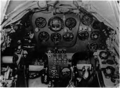
From the start, pilot comfort was made a high priority The cockpit was pressurized and air-conditioned, with a canopy that offered an excellent all-around view The aircraft was fitted with an ejection seat. The mechanical flying controls were statically and aerodynamically balanced at a time when hydraulic servo-controls did not yet exist A high degree of serviceability was also considered important Its structure and systems subjected to thorough research, the S aircraft was the result of a mamage of the rational and the useful It was not by chance that the general layout of the 1-310 (S)—the future MiG-15—was recognized as a classic and used for several Soviet aircraft (and even by other nations) during the 1950s Its preliminary design allowed for future updates linked to the development of new power plants armament, and equipment.
The 1-310—founder of a great family of experimental and production machines—proved to be one of the best combat aircraft of the second postwar generation Its top-notch performance is attributable to its optimum basic wmg load high thrust-to-weight ratio, easy-to-service armament, advanced structural technology, sturdy levered-suspension mam landing gear, and reliable engine
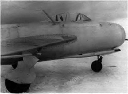
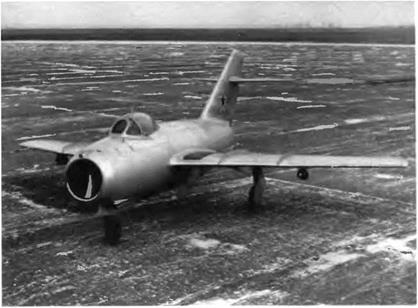
The mam features of this all-metal aircraft included a 35-degree swept wing with four fences a pressurized and air-conditioned cockpit, an ejection seat (the canopy was jettisoned first), and a two-section fuselage The armament included three cannons one N-37D and two NS-23s arranged at first like those of the 1-305 (FL) with all three muzzles on the same horizontal plane near the engine air intake For the first time on a Soviet fighter, fire warning and extinguishing systems were standard Also for the first time on a fighter, the aircraft was fitted with an OSP-48 instrument landing system that included an ARK-5 automatic direction finder with a range of 200 km (125 miles), an RV-2 two-level radio-altimeter, and an MRP-48 marker receiver Mating the two sections of the fuselage at the no 13 bulkhead allowed for easy access to the engine, its accessories, and its exhaust nozzle, facilitating engine removal or installation Mating the fuselage to the wings by means of attachment fittings meant that the aircraft could be assembled or disassembled quickly in field maintenance conditions and that, once taken apart, it could be transported in containers earned by ship, tram, or another aircraft
Assembly of the S-01 was stopped without notice as unexplained flameouts continued to hamper the development of the MiG-9 Engineer N. I Volkov, with the cooperation of MiG armament specialists,
|
|
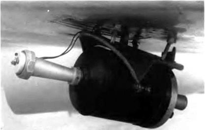
The second prototype or S-02 was equipped with small rocket engines beneath the wing to counter any spin, intentional or not, which could prove risky during test flights.
|
|
A close-up of the antispin rocket used for the MiG-15 tests
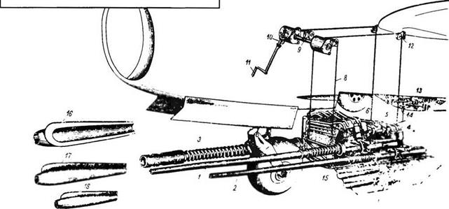
The ingenious device developed by N I. Volkov to help service and load the MiG-15’s three cannons worked on the same principle as a service elevator. (1) First NS-23KM cannon. (2) Second NS-23KM cannon. (3) N-37 cannon. (4-6) Ammunition boxes (7) Hinged panel (S) Cable. (9) Transmission shaft. (10) Drive shaft. (11) Hand crank. (12) Pulley. (13) Rear locking mechanism of the tray. (14) Locking mechanism’s key. (15) Tray. (16) N-37 shroud. (17 18) NS-23KM shrouds
|
|
|
|
|
proposed a revolutionary rearrangement of the cannons. He built a single tray for the three cannons, ammunition boxes, cartridge cases, and link outlet ports. This tray was embedded under the nose and could be lifted or lowered by four cables controlled by a hand crank, a drive shaft, and four pulleys—like a small service elevator. The idea seemed so inspired that it was immediately approved for use on the 1-310 The system made the cannons easier to load and service and also reduced the aircraft’s turnaround time when missions had to be flown at close intervals.
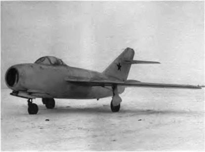
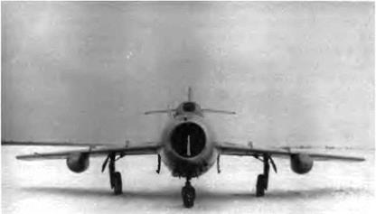
The front part of the S-01 was modified to accommodate this tray. Finished at last, the S-01 was rolled out on 27 November 1947 and made its maiden flight on 30 December with test pilot V. N. Yuganov at the controls. But right away sizable losses of thrust were recorded, and all flights had to be canceled. To remedy these losses, TsAGI and TsLAM engineers proposed reducing the length of the fuselage and the exhaust pipe slightly. This change necessitated modifications to the ailerons, the wing chord, and the sweep angles of the tail unit (which were increased). The well-known silhouette of the MiG-15 was not created in one pass.
The second prototype or S-02 joined the test program before long and flew for the first time on 27 May 1948, powered by a 2,225 daN (2,270 kg st) Rolls-Royce Nene II The state trials of the S-01 and S-02 were carried out at the GK Nil WS in two stages, from 27 May to 25 August and from 4 November to 3 December. The report concluded, “The 1-310 has passed its state acceptance trials; its performance was in accordance with calculations; and the preparation of the preliminary design for a two-seat version for pilot training [the UTI MiG-15] is recommended." Test pilots who flew the 1-310 were unanimous in their praise of the aircraft’s handling characteristics while taking off, climbing, and landing as well as its steadiness in flight and its maneuverability. In August 1948 the council of ministers of the USSR decided to order the 1-310 for the WS. It was given the military designation MiG-15.
The following details refer to the S-01.
Specifications
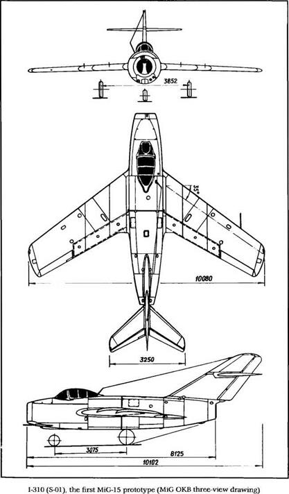
Span, 10.08 m (33 ft 1 in); overall length, 10.102 m (33 ft 1.7 in); fuselage length, 8 125 m (26 ft 7.9 in); wheel track, 3.852 m (12 ft 7.6 in); wheel base, 3.075 m (10 ft 1.1 in); wing area, 20.6 m2 (221.7 sq ft); empty weight, 3,380 kg (7,450 lb); takeoff weight, 4,820 kg (10,623 lb); fuel, 1,210 kg (2,667 lb); oil, 35 kg (77 lb); wing loading, 234 kg/m2 (48 Ib/sq ft); operational limit load factor, 8.
|
|
Performance
Max speed, 1,042 km/h at 3,000 m (563 kt at 9,840 ft); max speed at sea level, 905 km/h (489 kt); climb to 5,000 m (16,400 ft) in 2.3 min; to
10,0 m (32,800 ft) in 7.1 min; landing speed, 160 km/h (86 kt); service ceiling, 15,200 m (49,855 ft); endurance at 10,000 m (32,800 ft), 2.01 h; range, 1,395 km at 12,000 m (866 mi at 39,360 ft); takeoff roll, 725 m (2,380 ft); landing roll, 765 m (2,510 ft).


