MiG-1 and MiG-3 Series
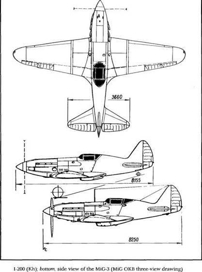
1-200 / Kh
In 1939 Soviet aircraft manufacturers, research scientists, and air force officers were taught a lesson by the poor performance of their planes in the Spanish civil war and against Japanese fighters in the Khalkin – Gol area of Mongolia. That lesson led to the acknowledgment of a severe failure.
It was just about time to update the fleet of the Soviet air force (WS). Most of its planes were old or obsolete. The Soviet government knew that Germany was preparing for war. Discreet reconnaissance flights conducted at extremely high altitude by Junkers Ju-86P-2s from the Luftwaffe’s Aufklarungsgruppe, a special unit commanded by Lt. Col. Theodor Rowehl, had not passed unnoticed. These flights were terminated after the signing of the Soviet-German "Friendship Pact” on 23 August 1939. It was in this context that the WS asked its suppliers to develop a single-seat interceptor offering its best performance at altitudes above 6,000 m (18,300 feet). A preliminary design, the Kh, was prepared by the Polikarpov OKB. Then in October 1939 the establishment of OKO-1, an experimental research unit outside the Polikarpov OKB, brought together M. I. Guryevich, V. A. Romodin, and A. I. Mikoyan. The new team took up the preliminary design of the Kh project and added a new and promising engine then being tested, the Mikulin AM-37, which was expected to generate 1,030 kilowatts (kW) or 1,400 chevaux (ch) of power above 5,000 m (16,400 feet). Unfortunately, the development of this engine proved to be much trickier than expected, so the design team had to make do with the only available supercharged in-line engine that offered the necessary power, the AM-35A.
All of the team’s efforts were concentrated on the new design, which was designated the 1-200. The program was of such urgency that only one hundred days elapsed between the first set of production drawings and the maiden flight of the first prototype on 5 April 1940.
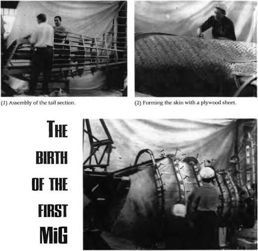
The 1-200 was built with the materials that were at hand: pine and birch plywood, fabric, and as little metal as possible, because Soviet production of special steel alloys and duralumin had fallen well short
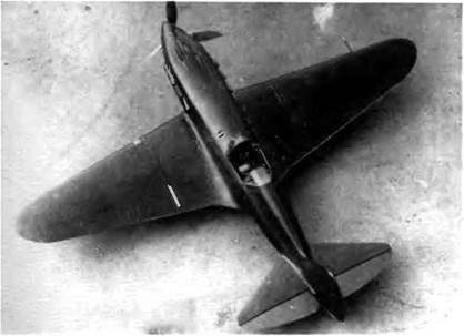
At rollout the 1-200 no. 01 prototype had only one oil cooler, on the left side of the engine (see three-view drawing). In these photographs there are two oil coolers, one on each side of the engine. The aircraft was modified in this way before its second flight. Bottom, pilots disliked the side-hinged canopy because it could not be jettisoned.
|
|
|
|
of demand. A detailed look at this machine is warranted because it is representative of Soviet technology and materials used at that time.
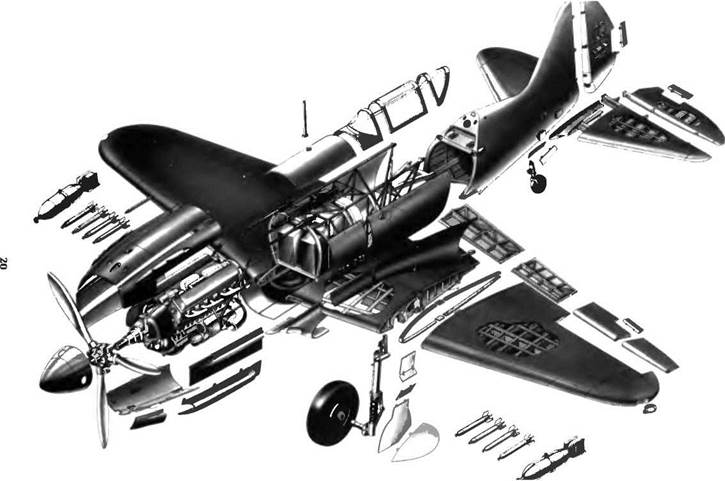
The wing had a single spar and a Clark YH-type airfoil section with a thickness ratio of 14 percent at the wing root and 8 percent at the wing tip. The all-metal structure of the wing center section consisted of an I-shaped spar with flanges in 20-KhGSA heat-treated steel and a web made of two 2-mm-thick stiffened light-alloy sheets; thirteen dural – pressed ribs, two of which were reinforced at the wing roots; two auxiliary spars, one on each side of the main spar; and five formers under the flush-riveted skin of the upper surface. The two 70-1 (18.5-US gallon) wing fuel tanks were located between the main spar and the rear auxiliary spar. The 110-1 (29-US gallon) fuselage tank was situated between the engine and the cockpit Fuel gauges were mechanically controlled.
The wing center section was attached to the fuselage by 6-mm bolts placed 60 millimeters apart. The skin panels underneath the fuel tanks were removable. The two single-spar wooden outer wing panels attached to the center section had a 5-degree dihedral. The spar was of the box type with a web made of seven 4-mm-thick plywood sheets (five sheets at the wing tips). The 14- to 15-mm-wide spar flange was made of delta-drevyesina, a densified wood. The spar box tapered from 115 millimeters wide to 75 millimeters at the wing tips. Front and rear auxiliary spars were made of pine plywood, and all ribs were made of duralumin, a light, strong alloy of aluminum, copper, manganese, and magnesium. The skin consisted of five 4- to 2.5-mm-thick sheets of Bakelite plywood applied diagonally (except in the leading edge area) and homogenized with casein glue. Both ailerons were metal-framed and fabric-covered. The all-metal, two-segment split flaps were pneumatically positioned at two settings, 18 degrees and 50 degrees. The wing aspect ratio was 5.97.
The fuselage structure was also of the mixed type. The front section, which extended from the nose to behind the cockpit, was made of welded 30-KhGSA steel tubes with twelve duralumin skin panels held by Dzus-type fasteners. The rear section (including the fin) featured a monocoque wooden structure made of four pine longerons, gusset plates in Bakelite plywood under the attachment points, eight hollow frames with a Bakelite plywood web, and pine stringers. The skin was made of five 0.5-mm-thick plywood sheets coated on the inside with strips of calico impregnated with a nitrocellulosic varnish and on the outside by glued calico. The cockpit was made of molded Plexiglas panels but was not bulletproof. Its hinges opened to the right.
Both legs of the main landing gear retracted inward into the center part of the wing, and there was an electromechanical position indicator
|
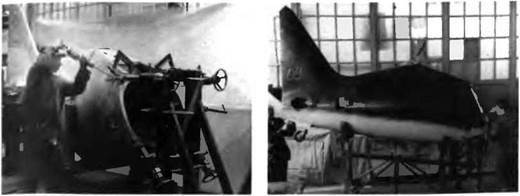
(5) Gluing it to the fuselage structure. |
|
|
|
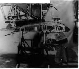
(6) The center section of the wing, gear down.
|
|
|
|
Exploded view of the 1-200 prototype (MiG OKB drawing) |
on the instrument panel. Shock struts were made of 30-KhGSA steel (130-150 kgf/mm2). The hydraulic fluid was a dialcohol (70 percent glycerin and 30 percent alcohol). The shock absorber stroke was 270-250 mm (10.6-9.8 inches) with an operating pressure of 39 + 1 atmospheres (573 psi). Main gear wheels were fitted with 600 x 180 tires. Wheel wells were closed by doors attached to the gear legs, two of them hinged to take into account the shock absorber stroke. The door covering the lower half-wheel was open 90 degrees when the gear was down and locked. The tail wheel (170 x 90 tire) retracted in a well closed by two small doors.
The cockpit panel was quite soberly equipped with only thirteen instruments. Noteworthy equipment and accessories included a GS-350 generator for the electrical system, a 12A-5 battery, and a KPA-3bis oxygen system. No radio was installed. Rod-operated mechanisms handled roll and pitch control (stick), while cable-operated ones provided yaw control (rudder bar). Trim control was maintained by means of a Bowden cable.
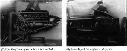
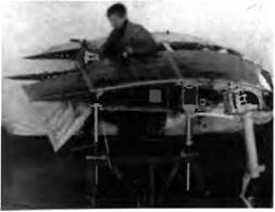
Through a reduction gearbox, the AM-35A engine drove a VlSh – 22Ye variable-pitch, three-bladed propeller 3 meters in diameter and fitted with a spinner made of elektron, a magnesium alloy It rested on welded 30-KhGSA steel mounts. This engine delivered 993 kW (1,350 ch) at takeoff but was particularly heavy at 830 kg (1,830 pounds). By comparison, the Klimov VK-105 weighed 600 kg (1,323 pounds), the Daimler-Benz DB-601 575 kg (1,268 pounds), and the Rolls-Royce Merlin 605 kg (1,334 pounds). In fact, the AM-35A was meant to power not a fighter but rather the TB-7 heavy bomber. For the same reason, it was fitted with a single-stage, single-speed supercharger that permitted a maximum continuous rating of 883 kW (1,200 ch) at 6,000 m (18,300 feet). The honeycomb radiator contained 40 liters (10.6 US gallons) of glycol. It was located in a ventral bath with a frontal area of 23 dm2 (2.5 square feet) and an airflow control flap at its rear end. There was only one oil cooler on the prototype, on the left side of the engine. Supercharger air intakes were located in wing roots, and the aircraft’s pneumatic system fed the air starter. The six exhaust pipes—one for every two cylinders—were made of EYal-TL-1 heat-resistant steel.
The first unarmed 1-200 prototype was moved from the factory to the Khodinka airfield on 30 March 1940. After taxiing tests, in which the aircraft briefly rose a few feet into the air, MiG chief pilot A. N. Yekatov made the first flight on 5 April 1940 Later he would be assisted by other test pilots such as M. N. Yakushin, A. I. Zhukov, M. K. Martselyuk, and M. N. Yakushin. The program’s chief engineer was A. G. Brunov, assisted by A. T. Karyev. On 1 May 1940 Yekatov was at the controls of 1-200 no. 1 during the yearly air parade above the Red Square in Moscow. Two more prototypes were hastily assembled. The second made its first flight on 9 May 1940, and on 6 June 1940 1-200 no. 3 had its turn.
In an exception to the normal practice dictated in large part by the urgency of the program, factory tests and state acceptance trials proceeded concurrently on the three prototypes. Test pilots and military engineers worked in close collaboration with the factory engineers. Some who deserve mention are S. P Suprun, squadron leader; A. G Kubishkin, flying officer; A. I. Filin, deputy chief of staff and manager of the air force test center; A. I. Kabanov, colonel; P. M. Stefanovskiy, squadron leader; A. G. Proshakov, captain; and A. G. Kochetkov, colonel and engineer.
The chief engineer in charge of the state acceptance trials was V. I. Nikitenko, first-class military engineer. They were carried out over a very short period of time. On 22 May 1940 Yekatov attained a speed of 648.5 km/h (349.9 kt) in level flight at 6,900 m (22,640 feet). Suprun took the second prototype past that benchmark, hitting 651 km/h (351 kt) at 7,000 m (22,965 feet).
Factory tests ended on 25 August 1940 after 109 flights lasting a total of forty hours and forty-nine minutes. State acceptance trials were resumed on 29 August and ended on 12 September 1940. Here, with all the starkness of its style, is an extract from the certification document signed by Lt. Gen. P. V. Richagov of the VVS. "The 1-200 fighter, powered by a AM-35A engine and built by Mikoyan and Guryevich at the NKAF factory no. 1, has a top speed of 628 km/h [339 kt], a better figure than those reached by other aircraft tested in our country, and is second to none when compared with foreign fighters in the same category when flown above 5,000 m [16,400 feet]. The aircraft has passed its acceptance trials successfully.’’
Though it was certified, the 1-200 was not an aircraft for inexperienced pilots. The flight tests had revealed poor longitudinal stability, heavy controls, and a tendency to stall at the slightest provocation and go into a spin, from which it was nearly impossible to recover. Moreover, due to the rearward position of the cockpit forward visibility when taxiing was very poor Yet the need was urgent, and despite all these flaws the government authorized an initial production run of one hundred aircraft. They received the service designation MiG-1.
Specifications
Span, 10.2 m (33 ft 5.6 in); length, 8.155 m (26 ft 9.1 in); wheel track, 2.78 m (9 ft 1.4 in); wing area, 17.44 m2 (187.72 sq ft); empty weight, 2,475 kg (5,456 lb); takeoff weight, 2,968 kg (6,543 lb), fuel, 190 kg (418 lb); oil, 28 kg (62 lb); wing loading, 170.2 kg/m2 (34.9 lb/sq ft).
|
One of the first eight MiG-1 s built in 1940. The side-hinged canopy was removed |


