“FAN SONG” INTERIOR
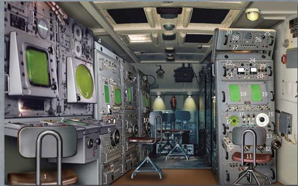
The cramped, poorly ventilated interior of the “Fan Song” UV van contained the range tracker at the far end, with two other officers tracking elevation and azimuth. All had control wheels and display screens in front of them, and their roles were interchangeable.
A fire control officer sat on the right side of the van and the missile technical officer and plotter managed the tracking and launch of the SA-2s. The battalion commander monitored the “Spoon Rest” radar screen and relayed instructions from Air Defense Headquarters by telephone or radio. He received target details that were transferred to a plotting board while the “Fan Song” was warmed up – it was put on “standby” when the target was within range. Automatic tracking (possible only against non-jamming targets) could be engaged sparingly using the two trough-shaped antennas, followed by missile guidance mode along the antennas’ narrow beams, but at the risk of attracting countermeasures activity. The SM-63 launchers were
turned and angled to the right position ready for launch. “Ready” lights illuminated when the missiles were prepared, and when the target was in optimum missile range the SA-2s were fired at six – second intervals. In “three point” mode the tracking officers operated their control wheels to keep the target, or jamming strobe image from aircraft with ECM transmitters engaged, in the center of their individual vertical displays. Guidance information from the “Fan Song” computer was sent to the missile via its uplink antenna (exposed at the rear of the main missile body once the booster rocket was jettisoned) to keep the SA-2 within the “Fan Song’s” narrow beam. Considerable skill was needed to keep the Mach 3 missile on target in the last stages of its flight, and greater accuracy could be gained from the “half correction” mode in which the missile was aimed with allowance for lead angle on the target, reducing the need for abrupt course corrections.


1. Battalion commander’s position
2. P-12/P-18 “Spoon Rest” radar controls and goniometer
3. RH-1 scope and Plan Position Indicator (PPI) screen
4. Range tracker’s console (NCO position)
5. Range tracking control wheel
6. Range tracking displays and controls
7. Elevation tracker’s console (NCO position)
8. Elevation tracking control wheel
9. Azimuth tracker’s console (NCO position)
21. Missile fuze setting selectors
22. Missile guidance control channel selectors
23. Radar mode selectors (wide angle/pencil beam/narrow beam)
24. Live fire button
25. Missile gyro controls
26. Radar antenna deploy switch
27. Radar power button
28. Generator power button
29. Target height/distance/velocity indicators
30. Power indicator lights


