SA-2 RADAR AND SUPPORT EQUIPMENT
 |
|
The majority of the system’s low-cost electronic elements were housed in its ground – based support vehicles. Within the missile’s 35.1ft body was the 5E11 Schmel or 5E29 radio proximity fuze, using either “strip” antennas on the external skin or a dielectric radome. Theoretically, the missile was accurate to within about 210ft, and the proximity fuze would be armed and programmed within that range via two waveforms within the command uplink channel. Alternatively, there was a simple impact fuze and a command fuze that could be used to detonate the warhead from the ground. The warhead itself was comparatively large to increase the chance of a kill from a “near miss” position. In its V-88 version the warhead weighed 420lbs and contained 8,000 metal fragments that would be ejected at a rate of 7,000ft per minute over a lethal diameter that could vary between 200ft at lower altitude and 800ft above 35,000ft.
|
|
 A hit by only a handful of these on an F-105’s hydraulic or fuel systems could cripple the aircraft.
The guidance system relied on three components — a command link receiver, an autopilot and a radar beacon at the rear of the missile to provide a tracking signal to the “Fan Song” guidance radar. The command link receiver operated with four pulse – modulated waveforms. Two of them supplied climb or dive and left/right turn commands to the missile’s powered steering fins after the booster was ejected. The other two provided programming and arming signals to the radio proximity fuze.
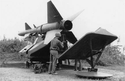
Missiles were transported on purpose-built, two-wheeled “transloader” semi-trailers pulled by a ZIL-157 tractor unit. An SA-2 could be transferred from the transport rail on the trailer to its SM-63-1 launcher by five men without additional lifting equipment. The launch rail of the SM-63-1 was lowered to the horizontal position and the missile on its transport rail was swung out at 90 degrees to the trailer. When the two rails were positioned end-on to each other the 5,042lbs SA-2 was simply slid backwards from one to the other by basic manpower and the relevant electrical connections were made, all within 10—15 minutes.
The SM-63-1 launch rail could be elevated up to 80 degrees and rotated through 360 degrees on a turntable — both the launch rail and the turntable were powered by electric motors housed in the launcher’s base unit. The “transloader” could be fitted with four wheels for quick transfer to another site. In launch position the rail rested on a foldable cruciform base with a movable blast deflector that would be lowered just before firing to reduce ground erosion from the exhaust.
|
|
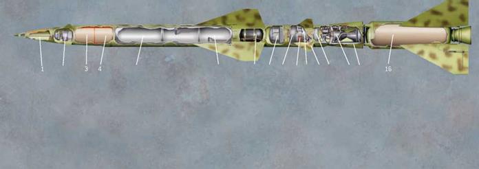
 SA-2 (S-75) "GUIDELINE” SAM CUTAWAY
|
|
|
|

1. Radio proximity fuze transmit antenna
2. FR-15 Shmel radio proximity fuze
3. V-88 high-explosive fragmentation warhead
4. Radio proximity fuze receive antenna
5. AK-20F oxidizer melange tank
6. TG-02 propellant tank
13. OT-155 Isonate turbopump gas-generator propellant tank
14. Isayev S2.711V rocket engine
15. Adapter fairing
16. PRD-18 boost powerplant with 14 tubes of NMF-2 propellant
The launch process began with early warning of an incoming raid from high – powered, low-frequency radars such as the massive A-band P-14 “Tall King”. An SA-2 battalion’s own search radar was the P-12 Yenisei (“Spoon Rest”), although the P-15 (“Flat Face”) search and track set and PRV-11 (“Side Net”) height-finding radar were also available.
Development of the VHF P-12 was commenced in 1954 by the SKB Bureau and culminated in the P-12NP in the 1970s. It could be retuned quickly to four pre-set frequencies and detect targets at 100—150 miles using 12 Yagi antenna elements that displayed their information on two scopes — an “E-scope”, showing the target’s height, and a plan position indicator.
Resistance to jamming and interference was steadily improved throughout the 1960s. “Spoon Rest-A” used two adjacent ZIL trucks, with the antenna array mounted on one and the radar indicators in another. Later versions such as the P-12NP separated the antenna into a remote trailer that could be located at a safe distance of up to 1,600ft from the operating unit. ARMs then homed on the antenna rather than the radar cabin.
Having acquired a target, “Spoon Rest” passed its range, bearing and altitude data to the RSN-75 “Fan Song” radar vans via land lines. Four vehicles were required for most versions. The radar antennas were mounted on the “PV” van, which also housed the transmitters. The battery commander and up to five operators with their command consoles were housed in the “UV” van. An “AV” cabin contained other tracking and transmitter equipment, while electrical power was generated by diesel motors in the “RV” van.
“Fan Song” had two functions — target acquisition of up to six targets and missile guidance of up to three SA-2s against a single target. Its operators refined the battalion “Spoon Rest’s” data to establish the exact position and flightpath of the target aircraft,
as well as calculating an impact point ahead of the target or as close as possible to it. 33
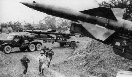
Members of a missile regiment run to their operational positions past spare rounds that are ready on their transloaders for each launcher. Assembling and fueling an SA-2 took several hours’ work, personnel having to handle hazardous substances in urban warehouse depots that were eventually targeted in the latter stages of Linebacker II. Camouflaging the missiles (as seen here) caused them to absorb heat, which could in turn damage the weapons’ internal electronics.
 (Author’s collection)
After launching, they then tracked both the target and the missiles’ transponder beacons — three SA-2s could be launched at a single target at six-second intervals. In automatic mode the radar computer calculated course corrections once the missile had been “captured” in the “Fan Song’s” narrow guidance beam and its spent booster had dropped away. This capture had to happen within about six seconds of launching otherwise the missile went ballistic and self-detonated after 60 seconds.
 |
|
Detonation near a target via the proximity fuze was indicated by a light on the “Fan Song” consoles. The narrow radar beam (only 7.5 degrees wide and 1.5 degrees in the scanning direction even in the upgraded “Fan Song E”) also limited the extent of maneuvering commands via the radio uplink in case the missile strayed beyond the bounds of the “Fan Song’s” guidance emissions. This gave US pilots their best chance of evading a missile, if they saw it in time. However, the computer could rapidly generate and transmit new steering commands if the target turned to a new course. To counteract jamming or the threat of anti-radiation missiles, the SA-2 crew could resort to manual modes without using the “Fan Song’s” guidance. Although this increased the missile’s reaction time for maneuvering, it required considerable skill to be effective.


