Yellow tips added to propellers, August 1941
Amendment No. 4 to Spec. 24114, dated August 28, 1941, added the use of camouflage enamel to Spec. 14109, specifying that only one coat of enamel need be applied versus the two coats of lacquer required, the resulting thickness being about the same for both types.
There was also a change to paragraph E-5, headed “Camouflaging of Propellers”, which stated that the tips for a distance of four inches from the ends of the blades were to be yellow in accordance with Shade No. 48 of Bulletin No. 41.
Fuselage Cocarde maximum size established, September 1941
The Air Corps Board, having completed most of the work on their camouflage studies, took issue with the size of the cocarde specified on the fuselage of camouflaged aircraft, because they felt that a cocarde which was three-quarters of the length of the projection of the fuselage side, would be entirely too large on some of the heavier aircraft the entering service, such as the Consolidated B-24, It would also possibly furnish an excellent bull’s-eye to an enemy at long ranges. They, therefore, recommended that the requirement be changed so that the diameter of the circle for the fuselage cocarde should be three-quarters of the length of the projection of the fuselage side. However, the diameter was not to exceed forty-eight inches (121.92 cm).
|
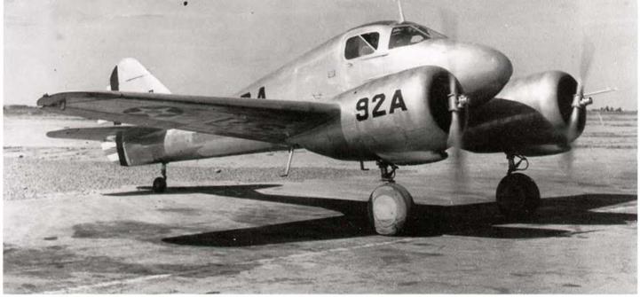
Cessna AT-8,41-5, was the first prototype, seen at Wright Field. Thirty-three of this version were built. Aluminum finish, with Material Division markings and Wright Field arrow on fuselage, (Harry Gann) |
 ■ ml
■ ml
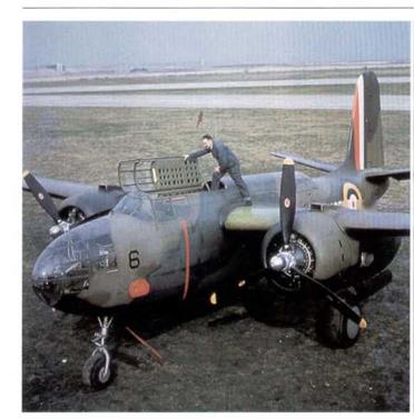
Douglas Boston Mk. П, AH435, aircraft No.6, with the short-lived tall fin stripes of 1940. Black propellers with yellow tips. The RAF camouflage is Dark Earth, Dark Green and Night. (USAF via Gerry R. Markgraf)
This recommendation was duly incorporated into Amendment No. 5 dated September 16, 1941, to Spec. 24114 and was the last change to be applied to the national insignia prior to World War II.
All non-combat aircraft, i. e, those which were not camouflaged, retained the cocarde and rudder stripes as specified in Spec. 98- 24102-K and amendments. Thus, the US Army Air Forces entered World War П with its combat and non-combat aircraft bearing national insignia in different positions. This was to be duly changed at a later date.
|
|
|
Curtiss AT-9, one of 791 built, was an all-metal transition trainer for light bomber trainees. Regarded as a “hot” aircraft, it proved to be more difficult to tly than the service aircraft it was training crews for: as a result it was phased out of service as more versatile trainers became available. Natural metal finish to Spec. 24113-A. (Harry Gann) |
|
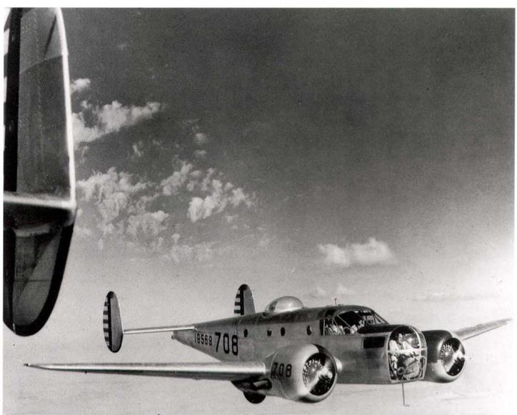
Beech AT-11 Kansan bombardier and gunnery trainer also evolved from the C-45. f,582 were built. Natural metal finish to Spec. 241I3-A. (USAF) |
T. O. 07-1-1A revision issued on October 28, 1941.
The last revision of T. O. 07-1-1, before the USAentered the war, was issued on October 28, 1941, and incorporated the changes
discussed above, in three main areas:
1. g Identification Markings:
(1) All identification markings, insignia, designators and squadron and flight command stripes on camouflaged airplanes will be of specification camouflage materials and of colors conforming to the color shades outlined in A. C. Bulletin No. 41.
(2) Airplane designators for camouflaged airplanes will be as specified in paragraph 8 c.
(3) Other identification markings, insignia, and organization identification will be as specified in paragraphs 5, 6, 7,
and 8.
h. Camouflaging of Propeller: The camouflaging of propellers as required by Spec. 24114 should be accomplished by spraying each propeller blade in a horizontal position and retaining the propeller in this position until the camouflaging materials have set, after which it will be necessary that the propeller be checked for balance. Tests indicate that one (1) coat of camouflage materials on propeller blades offers adequate coverage. It is anticipated that this finish on propeller blades will chip and become unsightly after a period of use, however, no attempt should be made to touch up the surface of the propeller blades at any time until the propeller is overhauled, at which time the assembly will be repainted and balanced.
8. b. Airplane Designators:
(1) Each Air Corps airplane, (including training types) regardless of whether equipped with radio, will be identified by a designator consisting of the radio call numbers for (hat airplane as specified in A. C, Circular 100-4. These designators will be painted on the airplanes as directed in paragraph 8c. herein.
 skill’
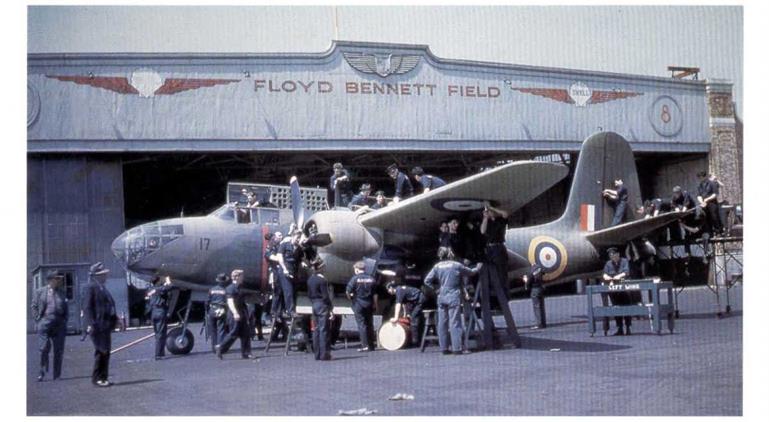
Douglas Boston Mk. HI, W8—, aircraft No. l7, is shown with the later short fin stripes. The camouflage is Dark Earth and Dark Green, plus Sky underneath. It is seen at Floyd Bennett Field prior to delivery. (USAF via Gerry R. Markgraf)
(2) Where insignia to denote rank or office of an individual is to be used in addition to the designator, the official insignia will be of a size in accordance with A. C. drawing No.41D658 and located and installed in accordance with A. C. drawing No. 41A656. The materials used in painting the official insignia will be restricted to the use of standard Air Corps specification materials and standard colors or blends thereof.
|
|
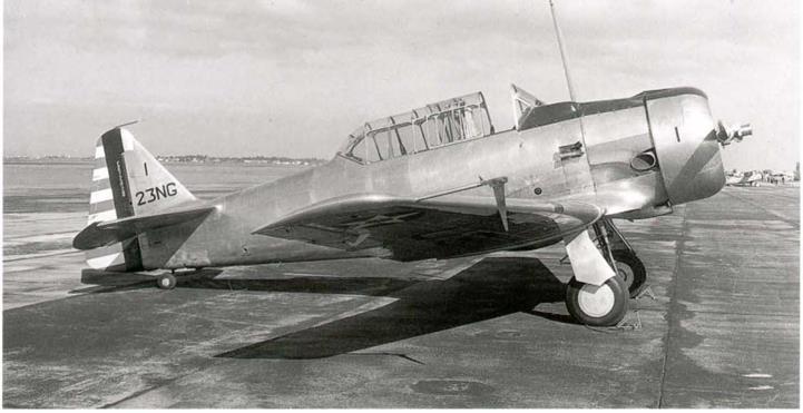
North American BC-1A, aircraft no. “1" of the 123rd OS, Oregon NG at Oakland in 1941. Natural metal finish to Spec. 24113-A. The white “line” on the rudder blue stripe is actually the dope code markings for the fabric, (F. Shertzer via William L. Swisher)
|
|
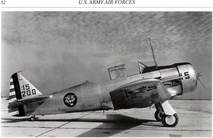
North American BC-1A, aircraft no. IS of the 120th OS, Colorado NG at Higgs Field, Fort Bliss, Texas on October 18, 1941. This aircraft has a beautiful unit insignia on the fuselage. (USAF)
|
|
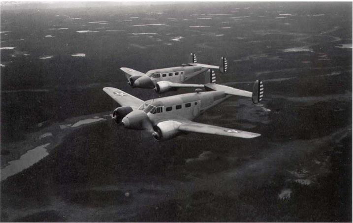
Two Beech F-2-BHs of the 1st Photo Group over Alaska in 1941. These were photographic reconnaissance aircraft, fourteen being modified from Beech B-18 commercial aircraft. Finish was to Spec. 24113-A, natural metal with large orange and green “Alaska” visibility panels on the wings, fuselage, and tail surfaces. (USAF)
Infra-red reflectance paint tested in Florida, November 1941,
A paint having high infra red reflectance was being subjected to an exposure test in Florida to determine its desirability. Aerial photographic tests had indicated that this paint offered definite advantages to prevent detection of ground camouflaged parked airplanes.
Spec 24114 “Camouflage Finishes For Aircraft", Amendment No. 6, December 12, 1941.
This spec, was revised only a few days after the United States entered the war and made the following changes:
Application.- One coat of zinc chromate primer, Specification AN-TT-P-656 was to be applied to all exterior surfaces. This was to be followed by one of two types of camouflage finishes as follows:
(1). Ail exterior surfaces, except for insignia and markings, were to be coated with two coats of camouflage lacquer, Specification No. 14105 or with one coat of camouflage enamel, Specification No. 14109. The lacquer was to be thinned by mixing approximately two parts of lacquer with one part of lacquer thinner. The enamel was to be thinned with approximately four parts of enamel to one part of enamel thinner. The enamel was to be so applied that a coating of approximately 1 mi) thickness was obtained.
|
|
|
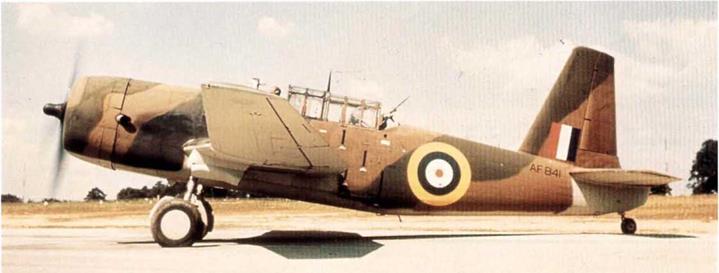
Vultee Vengeance Mk. II, AF841, runs up at Northrop Field, Hawthorne, California. It is camouflaged in Dark Earth, Dark Green and Sky. (via author)
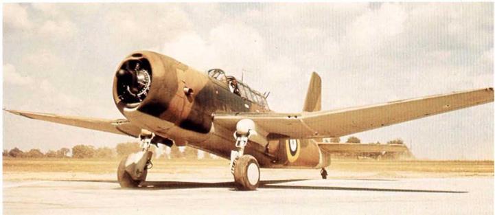
Vultee Vengeance Mk. 11, AK841, from front view, shows a total lack of underneath markings and the characteristic cranked wing shape, (via author) |
/
|
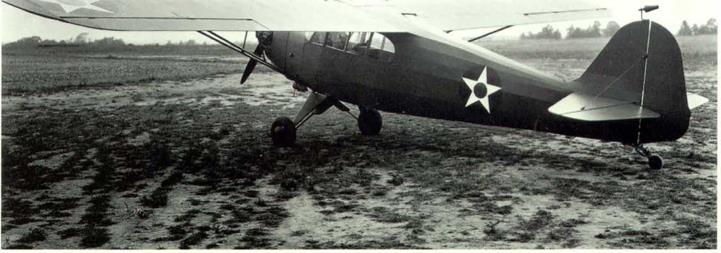
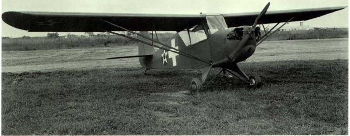
Taylorcraft YO-57, 42-452, was one of four obtained in 1941 to evaluate its use as a liaison and observation aircraft in close support of Army ground operations. Finish to Spec. 24114. (USAF) |
(2) . The entire airplane was to be coated with either lacquer or enamel. In no case was lacquer to be used for the upper surface and enamel for the lower, or enamel for the upper surface and lacquer for the lower.
(3) . Alt upper surfaces except for insignia were to be coated with dark olive drab, Shade 41 of Bulletin 41. The dark olive drab was to extend downward on the sides of the fuselage and all similar surfaces in such manner that none of the neutral gray coating was visible when the airplane was in normal level flight attitude and was viewed from above in any direction within an angle of approximately 30 degrees from vertical lines tangent to the airplane. The location of the color boundary line was subject to approval by the AAF.
(4) . All under surfaces, except for insignia and markings, were to be coated with neutral gray, Shade 43 of Bulletin 41.
(5) . Fabric covered surfaces, regardless of whether or not the finish of the metal surfaces was lacquer, or enamel, camouflage, Specification No. 14109, were to be finished as follows: (see original spec, issue of October 1940 – author).
|
Aeronca 0-58, one of a batch of twenty, ordered after four YO-58s were obtained at the same time as the Tkylorcraflt YO-57, for the same purpose. The 0-58s were upgraded with wider fuselages and more window space. Finished to Spec. 24114, with the 1941 maneuver markings on the fuselage. (USAF) |
The following new paragraph was added:
Camouflaging of Propellers.- All external surfaces of airplane propellers and hubs, after being cleaned, were to be sprayed with one coat of zinc chromate primer. The final finish was to consist of one tight coat of cellulose nitrate camouflage lacquer. During the finishing process, and until the final coat had set, each propeller blade was to be maintained in a horizontal position. The color of all external surfaces, except the tips, were to be black in accordance with Shade No. 44, Bulletin No. 41. The tips for a distance of 4 inches from the ends of the blades were to be yellow in accordance with Shade No. 48, Bulletin No. 41. After the propeller and hub had been camouflaged and prior to installation, the propeller assembly was to be checked for balance.
Civil Aeronautics Administration issues requirements for Flight Test Areas, Flight Procedures and Aircraft Markings, December IS, 1941.
After the attack on Pearl Harbor, the U. S. west coast was very apprehensive of being attacked by the Japanese. To cut down flying in the Los Angeles area, the CAA, in conjunction with the Fourth Interceptor Command, AAF, issued a memo to aircraft manufacturers and test pilots prescribing flight test areas in the San Diego and Los Angeles Metropolitan area. Flight plans were also required; all flights had to have the flight plan approved by the CAA before each flight was made. All aircraft flying in these areas had to be marked with the standard U. S. insignia on the upper left wing and on the lower right wing. The diameter of these insignias was to be 36, 48, or 72 inches, using the largest practical size.
In addition, the letters “U. S.”, in the largest possible size, and in a contrasting color to make them easily seen, were to be painted on both sides of the fuselage. These markings were to be in addition to the standard CAA civil markings. On December 17, 1941, a clarification was issued by the CAA, stating that the letters on the fuselage should have a width of at least two-thirds of their height. The width of each stroke was to be at least one-sixth of the height, and the space between the letters was also to be not less than one – sixth of the height. The letters were to be painted in a solid color and kept clean.
$ * % $ *


