Landing radar
On Earth, an aircraft’s altitude is conventionally determined by measurement of the external pressure. This makes use of the fact that as altitude is gained the atmosphere gradually thins in a well-understood manner. On the Moon there is essentially no atmosphere, so another method had to be devised to determine how high the LM was above the lunar surface. This was particularly important given the fact that there are few’ clues a pilot can use to determine speed or altitude by eye. There are no trees, roads or houses; no haze to give a sense of depth or distance. Most remarkably, there
|
The rendezvous radar antenna on Apollo 9’s LM Spider. (NASA) |
is little variation of topography as one descends from high to low altitudes. Just a pock-marked landscape of large craters overlaid with small craters, peppered with even smaller craters. Not that a pilot could manually fly the LM to the surface. The tight margins involved ruled that out. Good altitude information was needed by the computer so that it could fly an efficient path to the surface.
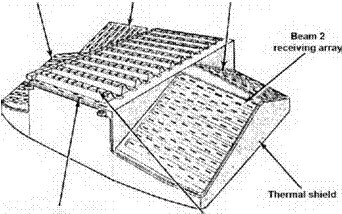
The way the lunar module made sense of its altitude above this landscape was by directing radio signals at it from an antenna mounted on the underside of the descent stage. One beam used Doppler techniques to determine the altitude and vertical velocity of the LM. Three more beams directed in a splayed pattern yielded the spacecraft’s horizontal velocity, again using the Doppler effect. Combined, the radar’s electronics could supply three-dimensional velocity information and altitude to the computer.
Whereas the initial landing missions flew over smooth terrain on their way to the touchdown, the later missions approached their landing sites over mountainous landscapes. To deal with this, the computer had a simplified model of the terrain profile added to its programming to compensate for the natural changes in height that would be encountered by the LM on its planned ground track. The computer also took account of the antenna’s slant angle; that is, its angle away from true vertical in which it was pointed at any moment. The data derived from the radar was not only used by the computer in its control of the descent. It also drove the tapemeter and cross-pointer displays for the crew.
The antenna operated in one of two positions, depending on the flight mode of
 |
Diagram of the landing radar antenna. (NASA)
the LM. Throughout most of the descent, the LM was flying on its back, with the crew looking up into a black sky. In this mode, the landing radar antenna was in its ‘descent’ position, angled 24 degrees from the LM’s vertical axis. For the final phase of the landing after pitch-over, when the LM adopted a more upright attitude, the landing radar moved to its ‘hover’ position to aim in a direction parallel to the spacecraft’s v axis and therefore pointing more or less straight down.


