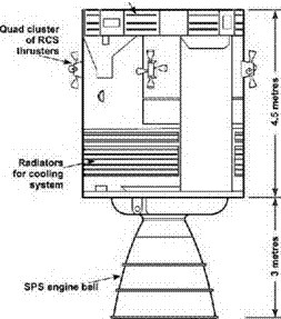
THE SERVICE MODULE
The cylindrical form of the service module consisted of a long central tunnel, with the volume around this divided into six sectors shaped like pieces of a cake. The structure was designed to support the weight of the command module and the launch
W. D. Woods, How Apollo Flew to the Moon, Springer Praxis Books,
DOI 10.1007/978-1-4419-7179-1 8. © Springer Science+Business Media. LLC 2011
 |
 |
The external and internal layout of the service module. (Redrawn from NASA source.)
escape tower, a load that increased by a factor of four towards the end of the Saturn’s first stage of flight. Its strength came from the beams and trusses of its internal skeleton, and the panels that subdivided its volume and formed its external skin. These panels were formed from a sandwich of aluminium honeycomb bonded between aluminium sheets and were therefore largely hollow.
The sectors around the tunnel were numbered 1 to 6. The first was one of the smaller sectors which subtended only 50 degrees and which was left empty for the early Apollo missions apart from a load of ballast that served to keep the craft’s centre of mass within limits. After the Apollo 13 explosion, an additional oxygen tank was added to this sector for Apollo 14. For the J-series missions that followed, this sector gained another tank filled with hydrogen in order to help to supply the increased power needs of these more demanding flights. Another modification for these intensively scientific missions was the addition into this sector of a suite of remote-sensing instruments and cameras to study the Moon from orbit.
Sectors 2 and 3 occupied 70 degrees and 60 degrees respectively of the volume around the central tunnel. They accommodated two large cylindrical tanks that held oxidiser for the SPS engine. Both they and the fuel tanks opposite were fabricated from titanium. The electrical power supply for the CSM was contained in sector 4 which, like its opposite number, swept only 50 degrees of the available volume. Three fuel cells were mounted near the top of the sector, towards the command module. They produced electricity by the reaction of hydrogen and oxygen supplied from
The service module 227
four tanks located in the remainder of the sector. As with sectors 2 and 3. sectors 5 and 6 accommodated a pair of titanium tanks for the SPS engine, in this case for fuel. In the central tunnel, two tanks of helium provided gas to pressurise the fuel and oxidiser tanks.


