High-energy fire
The reaction between hydrogen and oxygen is one of the most powerful sources of rocket thrust there is, with the exception of some highly exotic combinations that include fluorine as an oxidiser. Engineers are always keen to use it where possible owing to its high efficiency, its relatively benign properties and the clean exhaust it leaves behind – superheated steam. On the Saturn V, both the second and third stages used these two propellants in J-2 engines to pick up where the S-IC left off, achieve most of the speed required for Earth orbit and boost the Apollo spacecraft towards the Moon. Five engines were mounted on the S-II and a single example powered the S-IVB.
Outwardly, the J-2 might seem like a smaller version of the F-l engine but beyond having a chamber and nozzle fabricated from fuel-warming pipes, there were few similarities between these motors. In particular, because the temperature of the fuel was barely above absolute zero, the J-2 had to cope with two cryogenic propellants. Prior to start-up, and to prevent the propellants turning to gas as soon as they entered the engine block, the J-2 was pre-chilled by feeding a small amount of propellant through its components.
Two entirely separate Lurbopumps. driven from a single supply of hot gas, forced liquid hydrogen fuel (henceforth called LIF) and LOX into the combustion chamber. The high-pressure llows coming from both pumps were fed via control valves to the injector, where they entered the combustion chamber. The injector was very different from the drilled metal plate in the F-l engine. It consisted of a stainless steel mesh arrangement through which over 600 Lubcs-within-tubcs passed. These
|
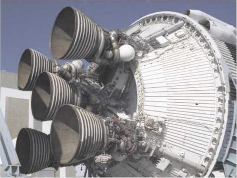
The five J-2 engines at the base of an S-II stage. |
carried LOX through their central passage and LH2 through the outer. Some fuel was diverted to cool the mesh.
An important component of the engine was a valve that could reduce the flow of LOX to the injector. This operation altered the thrust a little, but the point of having it was to allow the consumption of LOX and LH2 to be balanced over the length of the bum in order to ensure that the propellants were used equitably. Another important component was the spherical start tank – which was actually a tank within a tank. The inner tank held helium, whose pressure operated the engine’s valves. The outer tank held LH2 which would be released at engine start to spin the turbopumps before hot gas from a gas generator took up the task. In the restartable version of the J-2 for the third stage, this outer tank could be refilled with LH2 in preparation for its second burn – the burn that would leave Earth orbit and head for the Moon.
The starting sequence for the J-2 engine was equally as complex as that for the F-l and only a summary is within the scope of this book. The basic ignition source was the augmented spark igniter, NASA terminology for what was basically a spark plug which lit a flame source in the combustion chamber and which operated continuously throughout the bum. The main fuel valve was opened and LH2, pushed only by the fuel tank’s pressure, began to flow around the pipes that formed the engine’s walls, conditioning them to the fuel’s extreme chill. After a short delay,
 |
Diagram of the J-2 engine. (NASA)
the hydrogen in the start tank was discharged through the turbines of the two turbopumps to make them spin. The gas generator then began to burn LH2 and LOX to produce hot gas that would continue to power the pumps. The LOX valve was then opened which allowed LOX to begin to burn in the combustion chamber with the LH2 that had been circulating through the chamber walls. As the turbopumps spun up to full speed, this valve was slowly opened to bring the engine gently up to its rated thrust.


