EQUIPMENT
The Block II Apollo spacecraft
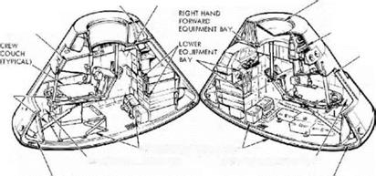
The command module was a stubby, conical craft almost entirely covered with a hcaishield that was thickest across its base, or aft. to sustain most of the punishment
|
|
|
|||
|
|||
|
|||
|
|||
|
|||
|
|||
|
|||
|
|||
|
|
||
|

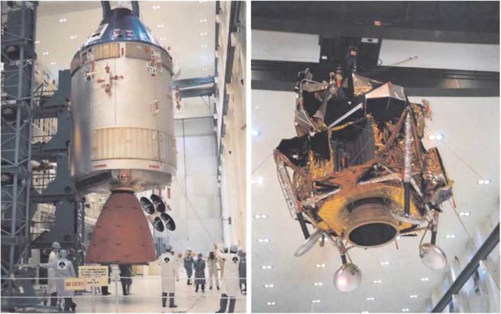
of re-entry. The outer rim of the cone was packed with small tanks, thrusters, various antennae and two small ports for the ejection of waste water and urine. The apex of the cone had a removable probe mechanism to enable it to dock with the Apollo lander and a tunnel through which the crew could transfer between the two
spacecraft. Parachutes were carefully packed around the outside of this tunnel, along with other paraphernalia of the Harth landing system.
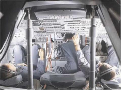
The main bulk of the CM’s volume was taken up by the pressure hull which accommodated three crew members and much of their electronic equipment. For lightness, the hull was constructed from two layers of aluminium sheet with an aluminium honeycomb in between. During launch and re-entry, the crew lay on couches with their backs to the aft of the spacecraft. Seating positions were defined by the roles of the crew. At the time of launch the commander (CDR) occupied the left couch for access to most of the flight instruments; the lunar module pilot (LMP) usually took the right couch and had responsibility for the spacecraft’s systems, as this was where many of the relevant switches and displays were located; and finally the command module pilot (CMP) generally had the middle scat, with his head next to the spacecraft hatch. For major manoeuvres in space, the CMP occupied the left seat. Directly in front of the crew and ranged around the entrance to the tunnel was the main display console – a vast panel of some 400 knobs, switches, meters and displays with which most of the flying of the spacecraft was achieved, in association with various hand controllers that sprouted from the armrests. Above the console, in the eye-lines of the commander and LMP. were two small forwardfacing windows. Other panels, windows and compartments were arranged around the crew. In particular, at the CM P’s feet was the lower equipment bay which included all the gear he would need to navigate the spacecraft, a task for which he was responsible.
Attached to the rear of the CM was the cylindrical SM that supplied most of the consumables; electrical power, water, air and cooling. It also carried an array of parabolic antennae for deep-space communication, thrusters for attitude control (iattitude being a wrord in spaceflight that means a spacecraft’s orientation; i. e. which way up it is) and the spacecraft’s main means of propulsion, an ultra-reliable, service propulsion system (SPS) engine that protruded from the rear. This engine took the crew’ into orbit around the Moon and. when their exploration had been completed, sent them back towards Harth. Over 16 tonnes of propellant for this engine was stored in four large tanks that occupied most of the service module’s bulk. Smaller tanks of oxygen and hydrogen provided the reactants for three fuel cells where a little chemical magic provided the crew with not only electrical power but also water good enough to drink. The tanks also supplied breathing oxygen for the CM’s cabin until separation from the SM.


