Environmental testing
An elaborate series of environmental tests were performed on all payload components, subassemblies, and the fully assembled payloads. The environmental testing philosophy included two types of test: (1) type approval testing of an engineering model payload and (2) flight acceptance testing of all flight models.
The primary purpose of the type approval tests was to assure that the basic designs were adequate to withstand the rigors of launch and the in-orbit environment. Those
CHAPTER 8 • GO! JUPITER C, JUNO, AND DEAL I 239
test levels were substantially higher than actually expected, to provide a margin of safety.
Flight acceptance testing was designed primarily to weed out errors in construction and early parts failures. Care was taken not to exceed the expected launch levels to avoid fatiguing any of the flight components.
Without going into the many details of test configurations and levels, the battery of environmental tests included (1) shock, (2) acceleration, (3) spin, (4) temperature (static, cycling, and long-duration), (5) combined temperature and vacuum, and (6) vibration.
A failure of the Engineering Model cosmic ray package during its type approval testing on 7 January caused considerable alarm. During the second vibration test, the GM counter rate was seen to be somewhat low. Upon closer examination, it was found that the ceramic insulator supporting the central wire in the counter had cracked within its encapsulation—a recurrence of another of the problems encountered earlier during testing of the Vanguard prototype instrument.
It was too late to change the design without delaying the Explorer I launch. Since the flight payloads had satisfactorily passed the lower-level flight acceptance tests, it was decided, with great trepidation, to proceed without modifying them. Luckily, the final flight instrument survived its launch, and the instrument operated perfectly in orbit.
The entire suite of tests ended with a measurement of the overall temperature characteristics of each completely assembled flight payload. They were placed in a temperature chamber and operated solely from their internal batteries. The GM counters were illuminated by a standard Co60 radioactive source. The resulting counting rates became the standard for operational checks made on the payloads at the launch site.
At the end of all Deal I flight payload testing, I calculated that the overall variation of GM counting rate with temperature would be in the neighborhood of 5 percent over the temperature range 0 degrees to 50 degrees centigrade. Although it would have been better to relocate an internal temperature sensor closer to the GM counter to facilitate more accurate correction of that temperature effect, it was too late to do so for Deal I. However, that was done for Deal II.30
All in-flight payload temperature data were tabulated at JPL and were used in correcting the GM counter flight data at Iowa.31
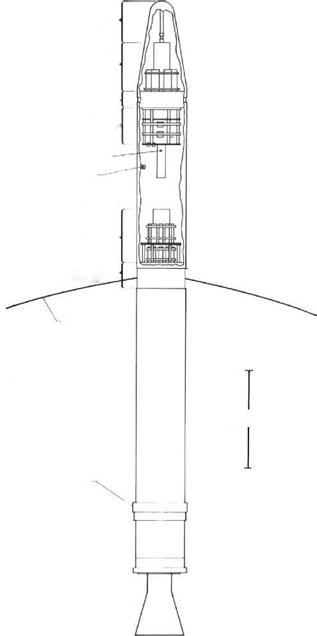
The Deal I satellite bore no resemblance to the Vanguard configuration. It was, however, similar to the configuration that we had worked out at Huntsville during the preceding summer, as can be seen by comparing Figures 7.1 and 8.4.
The first Deal I flight payload was completely assembled, tested, and weighed by 11 January. Its total weight, not including the Rokide thermal control coating on the shell and the fourth-stage rocket motor, was 18.51 pounds (some records list

 |
|
 OPENING SPACE RESEARCH
MICROMETEORITE GRIDS
FIGURE 8.4 The Explorer I satellite, including the final rocket stage below the central high – power antenna gap. The shell ofthetop instrument package is cut awayto showthe arrangement ofthe inside components.
|
CHAPTER 8 • GO! JUPITER C, JUNO, AND DEAL I
FIGURE 8.5 The Explorer I satellite spare instrument. The cylindrical shell and nose cone have been removed to show its construction. The vertical white stripes on the shell and cone controlled the temperature of the internal electronics. The identification of components was as shown in Figure 8.4. (Courtesy of the Department of Physics and Astronomy Van Allen Collection, The University of Iowa, Iowa City, Iowa.) |
18.13 pounds). By that time, the booster rocket and upper stages had been completed at ABMA and JPL and transported to the Cape. On 17 January, the Redstone booster was hoisted to a vertical position on Launch Pad 26A. Installation of the upper-stage rocket clusters followed, as the Jupiter C took shape.
In addition to an engineering development model, three flight payloads were assembled for the Deal I launch. Figure 8.5 shows one of them. The payload designations, the GM counters used on each, and their ultimate dispositions, as far as they are known, are tabulated in Table 8.1. The GM counter numbers are listed because they are the only identification durably impressed within the entire instrument packages, and therefore the only numbers that can be used to positively identify surviving payloads. The numbers are very faintly stamped on the GM counter stainless steel shells just above their threaded mounting flanges.
The space museum at JPL possesses a full-scale model of Explorer I, plus a cutaway version of the instrument. The cutaway instrument includes a cosmic ray counter and its electronics. As it is believed that only four of the complete Deal I packages were built, it is possible that this unit is the engineering model.
Additional models have been displayed from time to time. Those models are likely either prototype units prepared within JPL before the official decision to proceed with the Deal program, and therefore lacking the scientific instruments, or else spare parts
OPENING SPACE RESEARCH
|
TABLE 8.1 Disposition of the Deal I Instruments Deal I GM
|
![]() that appear authentic only when viewed from the outside, namely, antenna insulators,
that appear authentic only when viewed from the outside, namely, antenna insulators,
shells, and cones.


