Assembling and testing the instrument
The end of 1956 and beginning of 1957 saw a major change in emphasis. The focus changed to the merging of subassemblies to form a complete prototype package.
 |
138
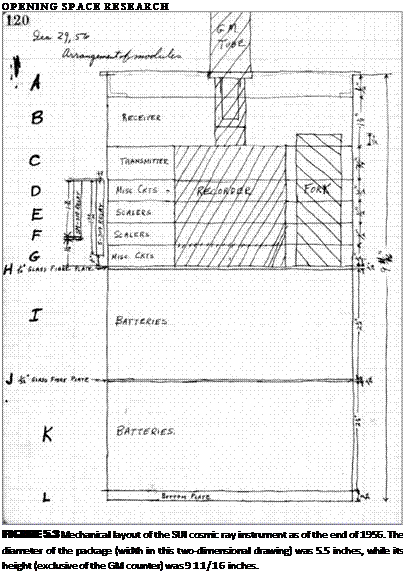
Robert Baumann had given me the first full set of dimensioned drawings of the satellite shell. It included details of the envelope for our instrument package and of the structure for supporting and thermally insulating it. With that information, I drew a diagram of the physical arrangement of our instrument package, as reproduced in Figure 5.3.18 That notebook sketch was followed by a detailed weight breakdown that totaled 13.3 pounds (including the telemetering system and its batteries).
Thus, by the end of 1956, all of the key satellite and instrument features and parameters had been established.
CHAPTER 5 • THE VANGUARD COSMIC RAY INSTRUMENT 139
The Vanguard instrument testing program The satellite had to operate in a previously unencountered physical environment. The effects of a completely isolated thermal environment for an extended period were unknown. It was expected that the satellites would be subject to small dust particles traveling at great speed, but their numbers and sizes were unknown, so that their effect on the satellite could not be predicted. The satellite and its internal instruments would have to survive the extreme vibration and acceleration of the rocket launches.
The attempt was made to design the satellite to operate over as wide a range of the environmental parameters as possible to span the range of uncertainties. An elaborate testing program was devised to verify the design, as well as to weed out any incipient component failures. Homer Newell had informed us as early as November 1955 that the expected conditions for the satellite instruments included operation over a temperature range of at least 41 degrees to 122 degrees Fahrenheit (5 degrees to 50 degrees centigrade). He also indicated that the instruments would have to survive spin rates of250 to 400 revolutions per minute and very high initial linear acceleration values.19
The testing program continued to evolve. On 7 May 1956, a more complete set of conditions was promulgated:20
• Operation in a complete vacuum
• Operation after a temperature cycle lasting 90 minutes from values of -28 degrees to +104 degrees Fahrenheit (-30 degrees to +40 degrees centigrade)
• Survival of sinusoidal vibration at levels of 8g (eight times the Earth’s gravity), varying in frequency from 20 to 2000 cycles per second, with tests lasting for 10 minutes in each of three mutually perpendicular directions
• Survival of random vibration (similar to acoustic “white noise”) at levels of 20 g RMS, with a uniform spectral density in the range 20 to 2000 cycles per second, with tests lasting for five minutes in each of the three mutually perpendicular directions
• Survival after a steady acceleration of 50g for 15 minutes along the primary axis
Final test specifications were issued at the December 1956 meeting.21 There were to be two series of tests. The first series, of design level tests, was to help assure that the instruments could survive the launch phase and then operate over an extended period in space. Those levels were set somewhat higher than the levels actually expected to occur, to provide some extra margin in the design. As those tests might overstress the hardware and components, the design test hardware would not be flown.
The second set of tests, referred to as flight acceptance tests, were to be applied to all flight payloads. They were carefully set at levels that would not unduly stress
 OPENING SPACE RESEARCH
|
the instruments but that would help detect deficiencies in assembly and incipient weaknesses of electronics components and mechanical assemblies.
Responsibilities for conducting the tests were also established at that meeting. In Iowa City, we were to run design-level vacuum and temperature tests on our subassemblies and the complete prototype instrument package, and design-level vibration tests to the limits of our capabilities at Iowa. As it turned out, all vibration tests were performed at NRL, since we were unable to obtain the necessary test equipment at Iowa in time for the tests.
The NRL was responsible for design-level vibration tests of a prototype data recorder in late January 1957 and of a complete Iowa prototype package in midMay. They would also perform the vibration and acceleration tests for the complete satellite. And they would be responsible for the entire gamut of acceptance tests (vacuum, temperature, temperature cycling, vibration, and acceleration) for the flight hardware. Those were scheduled to begin on 15 June.
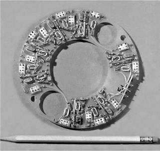
February 1957 As we entered 1957, I completed the assembly and initial temperature testing of the first flight-realistic electronics deck, a binary scale of 128. That test item is pictured in Figure 5.4. Other major work included GM counter measurements, tape recorder tests, preliminary design of a 700 volt power supply for the GM counter, design and testing of the tuning fork time standard, and assembly of the second electronics deck.
CHAPTER 5 • THE VANGUARD COSMIC RAY INSTRUMENT 141
We were especially concerned about the ability of the GM counter and tape recorder to withstand the expected vibration and acceleration levels. Special tests of those components were conducted in the NRL vibration test facilities on 18 February.
I referred to the package that I assembled for that test as prototype unit 1, or simply PT1. Although some of its circuit boards and battery modules were dummies, the GM counter and tape recorder, along with minimal circuits and batteries to operate them, were mounted in a realistic manner. The packages assembled later for the June, August, and October tests were referred to in my working documents, respectively, as PT2, PT3, and PT4.
Robert Baumann, several of his technicians, and I installed PT1 in one of the early NRL-designed satellite shells. In addition to testing our package, the vibration test was intended to test a number of mechanical features of the shell, as well as an array of solar cells that the NRL engineers were considering for use on later satellites.
With fingers crossed, we began the tests. They consisted of three sets of runs, one along the instrument’s vertical axis, that is, along the launch rocket’s primary thrust axis, and others along two mutually perpendicular horizontal axes. A series of four tests covering different frequency ranges and with increasing vibration amplitudes was to be completed for each of those orientations.
The first set of runs along the vertical axis was completed without incident. Runs along the first horizontal axis were also satisfactorily completed. But the test series along the second horizontal axis, with sinusoidal vibration sweeping over the frequency range 2000 to 16 cycles per second, resulted in a number of failures. Specifically, (1) two antenna rods broke off, (2) the satellite shell cracked at its bottom because several screws had loosened, (3) the bottom broke out of the NRL-supplied instrument container, (4) two Kel-F thermal insulators broke, and (5) the satellite internal support tubing broke in two places. There is little doubt that one or some of those failures caused others, but there was no way to determine which one occurred first and precipitated the chain of events.
Happily for me, my instruments survived the tests with no failures—there was no damage to either the GM counter or tape recorder. [1]
OPENING SPACE RESEARCH
 great confidence in their work and led, eventually, to the collaborative arrangement whereby they designed the high-voltage power supplies for the GM counters and supplied component parts kits that we assembled in the early Explorers.
Returning from Fort Monmouth, I stopped for a visit with Gerhardt Groetzinger at the Glenn L. Martin Company’s Research Institute for Advanced Studies (RIAS) in Baltimore, Maryland. He was developing a cosmic ray ion chamber that he hoped to fly in the Vanguard program but that eventually flew on Explorer 7. Needing long-term data storage, he was interested in my tape recorder, and I showed him my plans, a sample recorder, and a sample scaler deck. Eventually, I supplied him with complete tape recorder fabrication plans and a sample unit, and he incorporated it into his instrument design, as described in Chapter 14.
In early March, Ed Manring from the Air Force Cambridge Research Center visited us in Iowa City, and we began detailed planning for integrating their micrometeorite instrument into our package. That marked the beginning of a very enjoyable working relationship that resulted in the inclusion of their instrument in the Vanguard payload and on the later Explorers I, II, and III.
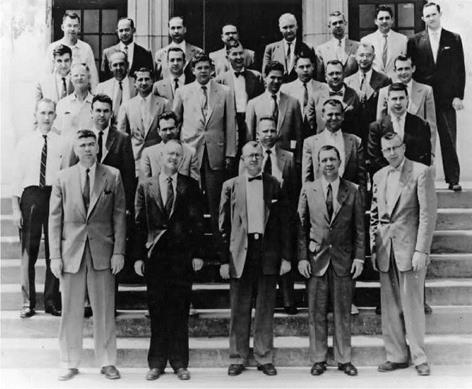
April 1957 All Vanguard satellite designers met again at NRL on 24 through 27 April 1957 (Figure 5.5).23 That gathering began with brief status reports by Bob Baumann (satellite structure), Roger Easton (Minitrack), Whitney Mathews (telemetry), Jim Heppner (magnetometer experiment), Herman LaGow (environmental experiments), Herbert Friedman (Lyman-alpha experiment), the author (cosmic ray experiment), Ed Manring (micrometeorite experiment), Vern Suomi (radiation balance experiment), Bill Stroud (cloud cover experiment), and Warren W. Berning (resonant reflecting dipole experiment). Working sessions with the experimenters and individual NRL engineers occupied the next several days.
The working sessions were followed by a meeting of Van Allen’s Working Group on Internal Instrumentation. At that meeting, held in the old “temporary” Navy building T-3 on the west end of the Washington Mall, each experiment group gave a status report reflecting their progress.
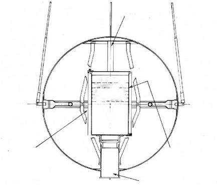
My SUI report contained a final block diagram of the instrument, a description of its operation, and a summary of our status. It also included a drawing of the arrangement of our instrument in the satellite shell, reproduced here as Figure 5.6. I showed models of our instrument mockup and the tape recorder, and reported in detail on our power and weight requirements. My report concluded with the statement, “SUI expects to be able to deliver the first instrument package, complete in every respect and operating, to NRL for vibration testing on 15 June 1957. We further expect to deliver three flight units to NRL on 1 August 1957 which are to be given acceptance tests by NRL during the six months period following that date.”24
|
CHAPTER 5 • THE VANGUARD COSMIC RAY INSTRUMENT
FIGURE 5.5 Group picture of most of the participants at the April 1957 working meeting at the NRL, taken on the entrance steps of NRL Building 43. From left to right, starting with the front row: Warren Berning, Homer Newell, Bill Stroud, James Van Allen, and Vern Suomi. Second row: Jim Heppner, Jessie Mitchel, Rudy Stampfl, Rudy Hanel, John Maskaski, and George Ludwig. Third row: Luc Secretan, identity unknown, John Licht, identity unknown, Ed Rich, and Bob Stroup. Fourth row: Roger Easton, George Hunrath, identity unknown, Hans Ziegler, Bob Baumann, and Milt Schach. Fifth row: Marty Votaw, Maurice Dubin, identity unknown, Ed Manring, Whitney Mathews, Ed Bissel, Karl Medrow, and identity unknown. (Courtesy of the Naval Research Laboratory.) |
My notebook entry on 3 May 1957 indicates that I was, by then, providing detailed information about our cosmic ray instrument to Ernst Stuhlinger at the Army Ballistic Missile Agency in Huntsville, Alabama.25 That was to permit their group to move forward with the off-the-record development of a scientifically useful satellite for the Jupiter C launch vehicle. That preliminary work laid the foundation for the shift of our instrument from Vanguard to the Jupiter C launch vehicle following the Sputnik 1 launch, as related in Chapters 7 and 8.
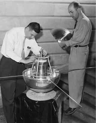
June 1957 We were tremendously excited on 6 May, when the first aluminum prototype satellite shell arrived.26 Wayne Graves and I immediately tried fitting our evolving prototype instrument package into the satellite, as shown in Figure 5.7. To our considerable relief and elation, it fit perfectly!
 |
|
 |
 PACKAGE
SEPARATION DEVICE
FIGURE 5.6 Drawing of the Vanguard cosmic ray satellite as of April 1957. The central cylinder with the stack of decks is the instrument package that we were assembling at Iowa. The shell, antennas, and internal structure were developed and produced by NRL.
We were working toward an all-up vibration test on 15 June. The test was actually conducted on 27 May. As that date approached, Wayne Graves, Riley Newman, our other student helpers, and I worked feverishly into the late evenings to ensure that the tests would be as comprehensive as possible. It became clear, however, that the instrument package would still be incomplete. Nevertheless, I still hoped to prove the physical design of the overall package and the operational viability of a major portion of the electronics. One of the most pressing specific objectives was to make a full and meaningful test of the tape recorder, including its control, recording, and playback capabilities.
Arriving in Washington, D. C., on Sunday, 23 June, hand carrying my instrument package in its wooden carrying case, my ever-present toolbox, and a kit of supplies, I began the next morning with some of the final preparations of our prototype (PT2) on a bench in the NRL facilities.
By Wednesday evening, with the vibration test set for the following morning, I still had to complete the master interconnecting wiring harness and to verify that the fully assembled package was operating properly. In my hotel room, at its small writing
|
CHAPTER 5 • THE VANGUARD COSMIC RAY INSTRUMENT
FIGURE 5.7 Fitting the partly completed but physically realistic cosmic ray instrument package into the NRL-provided Vanguard satellite structure. The author is on the left, and Wayne Graves is holding the top half of the shell. |
desk, with my soldering iron plugged into a nearby convenience outlet, and with the test equipment, hand tools, kit of wire, and other supplies that I had carried from Iowa, I worked on that final wiring late into the night. At about 2:00 on Thursday morning, it was done. The package as it existed at that time included the fully operational transmitter, modulator, subcarrier oscillator, calibration system, binary counters, and battery stacks. The receiver was included but not working, apparently due to a transmitter interference problem that would have to be worked out with the NRL engineers. Provisional tuning fork timing and recorder stepping circuitry would also be replaced by improved designs.
After a few hours’ sleep, I drove to NRL in south D. C. on the morning of 27 June to help in setting up for the vibration tests. The NRL teams had also been working hard—by the time I arrived, they had completed the assembly of the satellite shell, the interior instrument support structure, and the jigs for physically mounting the satellite on the vibration table. We inserted my instrument package into the shell, connected
OPENING SPACE RESEARCH
![]() the radio frequency harness to the antennas, activated the instrument, verified its operation, closed the access port, and mounted the fully assembled package on the vibration table.
the radio frequency harness to the antennas, activated the instrument, verified its operation, closed the access port, and mounted the fully assembled package on the vibration table.
Four series of design-level verification tests were planned at progressively higher vibrational levels.27 Each series consisted of three runs, first with vibration along the thrust axis (vertical), second with vibration perpendicular to the thrust axis (horizontal), and third, also with vibration perpendicular to the thrust axis, but 90 degrees from the previous tests. All runs were to be of four minutes’ duration, with vibrational acceleration within the frequency band 10 to 2000 cycles per second. The levels were to be at 15,20,25, and 30g along the thrust axis and at 10,15,20, and 25 g along the two transverse axes.
During the first run, with vibration along the thrust axis at 15 g, the calibration relay contact bounced, but it operated satisfactorily after the run. During the second run, with vibration horizontal at 10 g, the calibration relay operated properly but was intermittent after the run. The run along the other horizontal axis was satisfactory. The second series of three runs, at 20 g vertical and 15 g horizontal, was satisfactory.
It was when we began the third series that we ran into serious trouble. Following the initial run along the vertical axis at 25 g, we discovered a loose screw and locknut inside the shell. Since that threatened the mechanical integrity of the entire assembly, we immediately stopped the tests. I discovered that the GM counter was hot to the touch and, upon checking further, found that an abnormally high current was being drawn from the batteries powering its high-voltage power supply.
Thus, the test results were mixed, requiring a return to the design laboratories at both NRL and Iowa City. They would have to address the problems with the satellite shell and internal structure, and I would have to tend to the GM counter and relay problems.
Upon further checking the instrument package back in Iowa, I discovered a small crack in the GM counter’s ceramic insulator. It had allowed some of the internal gas to escape, causing it to arc and fail.
The 700 volts required to operate the GM counter presented a special problem. That voltage can be easily managed at sea level pressure where even a small air gap provides adequate insulation. However, as the air pressure is reduced, some electrons can pass across the gap, and a phenomenon called corona discharge begins to occur. That results in a high current flowing between the conductors, effectively shorting out the GM detector. The net result of that process is interference with the operation of the counter, overheating of components, and, eventually, destruction of the power supply.
The original design called for the Vanguard cosmic ray instrument to be sealed in an airtight container. As long as normal atmospheric pressure was maintained
CHAPTER 5 • THE VANGUARD COSMIC RAY INSTRUMENT 147
within that container, the corona discharge would not occur. However, we wanted to protect against the possibility that the container might leak. That required sealing all conductors carrying high voltage with some type of solid insulating material. However, the epoxy that we tried constrained movement of the base of the counter where its insulating terminal and seal were located. Vibration flexed the assembly enough to crack the epoxy and insulating terminal. That allowed some of the counter’s gas to escape.
It was clear that I had to improve the high-voltage insulation. That problem continued to plague me in one form or another throughout the next 18 months, including during my later work at JPL.
Despite that result, I was optimistic, as my package’s overall mechanical design seemed to be sound. Other than the problems with the relay and counter, operation was satisfactory for all of the package’s electronic components and circuits, and the electromechanical tape recorder operated satisfactorily both during and after the tests.
That Monday, 1 July 1957, marked the official beginning of the IGY. Many individuals in the United States were working hard to make sure that we could launch a satellite during the next 18 months.
August 1957 Another vibration test at NRL was due in mid-August. We set about to put the prototype instrument package, referred to by then as PT3, in what we hoped would be its completed form. On 19 August, I boarded the plane for Washington, again hand carrying the prototype unit. After several days of work to install the instrument package in the satellite shell and set it up for the test, the all-important vibration test was made on 22 August.
The problem with the GM counter had not been solved. I had encapsulated the entire end of the GM counter and its mounting flange in a block of solid epoxy. Sometime during the second test, arcing again occurred. It caused the recorder tape to be nearly blank, even though the recorder operated perfectly throughout the test. The blank tape was a result of the method of encoding the data. Blank recordings were to be seen later after the successful Explorer I and III launches, when the pulse rate from the counter was very high for a different reason. That is a story of its own, as related in Chapter 12.
We continued with more of the vibration tests. In addition to the GM counter problem, several problems were again encountered with the satellite structure. Shortly before the final run, we noticed that the top of the satellite shell was deformed, and upon opening it, we found that our instrument package had broken entirely away from its supporting structure. Although it had been bouncing around for the last bit of the test, slamming against the top of the satellite shell to dent it, there was no apparent damage to our instrument. Thus, I was pleased with the instrument design
OPENING SPACE RESEARCH
![]() and construction, including the fact that the tape recorder had behaved as planned. I returned home the next day.
and construction, including the fact that the tape recorder had behaved as planned. I returned home the next day.
Careful examination of the GM counter back in Iowa City revealed that the latest encapsulation technique still did not cure the problem. Although the block of epoxy firmly anchored the ceramic insulator, the swaying of the rest of the counter relative to its mounting flange again cracked its insulator. After that test, I worked out a variation of the encapsulating and mounting arrangement that permitted the counter and its insulator to move in unison without damage.
After those tests, NRL was under even greater pressure to improve the design of the satellite internal structure. At Iowa, in addition to further work on insulating the GM counter, I needed to make a number of additional changes to clean up our design and make its operation more dependable.
But first, I wanted a break. During the last week in August 1957, I left the frenetic pace at the laboratory for some rest and recreation with my much-neglected family. We had discovered the attractions of family camping vacations during two trial camping trips during the preceding summer. A short stay at Devils Lake, Minnesota, for our first introduction to tent camping was followed two months later by tent camping along the way as we drove west to visit Rosalie’s family in Seattle. Those were highly satisfying experiences and showed us that camping (true camping, in a tent) provided a complete break from the pressures of work and home, a valuable collective family experience, a close contact with nature, the thrills of encountering new horizons, and an inexpensive way to take extended vacations.
We were so excited by those early camping experiences that we decided to undertake our first extended pure-camping trip. That last week in August, Rosalie and I took preschool-aged Barbara and Sharon on a six day canoe-camping trip. This was in the Boundary Waters Canoe Area in the Quetico-Superior Parks in northern Minnesota and southwestern Ontario. Driving through Ely, Minnesota, to the end of the road, we rented a canoe at the southern end of Moose Lake. From there we canoed and portaged across Moose, New Found, and Ensign lakes and passed onto Bass Lake, where we found an isolated, small island that served as our home for the next four days.
We were amazed by the diminution of human presence that resulted from the portages. Moose Lake, accessible by road at its south end, and New Found Lake, directly connected with Moose Lake, were crowded along their lengths with canoes, sailboats, and speeding motorboats. After a short portage of about 25 rods, on Ensign Lake, we encountered only three canoes (one with a small outboard motor) during the time it took to traverse it. The portage to Bass Lake was 53 rods, enough to cut the average traffic density to only three canoe parties per day (none with motors).
CHAPTER 5 • THE VANGUARD COSMIC RAY INSTRUMENT 149
In addition to the absence of people, the seclusion of the island in Bass Lake had additional advantages—fewer bears and mosquitoes. We all had a great time with the routine of camp life, hiking, fishing, very brief dips in the frigid lake, sitting around the campfire, and restful sleep. We started as camping novices but ended with enough confidence to undertake many camps throughout the United States during the entire period that the children remained at home. Even after the children left, Ros and I continued our camping forays for many more years.
We returned much revitalized to our home on Rochester Avenue on Saturday, 31 August. After a Sunday to reestablish our usual home routine, Rosalie began arranging for another important family milestone, Barbara’s entry into kindergarten. And I went back to the laboratory.
October 1957 I looked forward to the push to deliver our prototype instrument package for what we hoped would be its final acceptance tests. As indicated earlier, that was already running several months late, partly because of the immensity of our task in completing the instrument, but also because of delays at the NRL in completing the final satellite shells, antennas, separation mechanisms, receivers, and transmitters. Both NRL and we were saved from major embarrassment, however, by the fact that the launch vehicle development was lagging substantially. Nevertheless, we all felt tremendous pressure.
During the summer, my only enrollment for university credit had been in research, and my work on satellite development easily fulfilled that requirement. In September, I felt that I had to continue pushing toward my degree with my course work and signed up for Theoretical Optical Physics and Quantum Mechanics, two very challenging courses. It turned out that they had to be dropped later when our program was shifted to the Jupiter C launch vehicle.
During the following weeks, I busied myself on many final details. My first substantial task was to process and analyze the data that had been recorded during the recent vibration tests at NRL. I continued with temperature and vacuum tests of the recording and playback amplifiers and worked on final assembly of the full instrument stack.
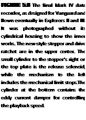
I also hurried to make another change in the tape recorder. I had a growing uneasiness about the Mark III tape-advancing ratchet drive. By good fortune, Frank McDonald brought a newly available component to my attention—a solenoid that was designed at G. H. Leland Inc. to rotate wafer switches. I quickly adapted that device, resulting in the final Mark IV recorder, as seen in Figure 5.8. That final version of the tape-advance drive was fully balanced for steady state rotation, translational acceleration, shock, and vibration, and it operated dependably throughout the rest of the developmental program, and, eventually, in orbit.
 |
 |
OPENING SPACE RESEARCH
I was in the final stages of making the conversion to the Mark IV recorder when the Soviets orbited Sputnik 1 on 4 October 1957. I continued with that task for a short time, even after I began talking to JPL and Vanguard program officials and engineers about shifting our instrument from the Vanguard to the Jupiter C launch vehicle. The final solenoids and ratchets were prepared in the University of Iowa instrument shop but were fitted onto the flight units at JPL after I arrived there.
In mid-September, Kittl at the Signal Corps Engineering Laboratories reported on the results of their efforts to design a good high-voltage power supply to drive the GM counter. Superior to my design, it was immediately adopted for inclusion in our package. They delivered a working unit near the end of September, and then collected and pretested kits of parts, which we assembled on our circuit boards. Through that arrangement, I developed great admiration for the highly competent engineers at the Signal Corps Engineering Laboratories. The ones with whom I worked most directly were, in addition to Kittl, Paul Rappaport and George Hunrath.
I completed my preparations for the next vibration test a little ahead of schedule, so that I could attend the CSAGI Conference on Rockets and Satellites in Washington,
CHAPTER 5 • THE VANGUARD COSMIC RAY INSTRUMENT 151
D. C., during the week of 30 September through 5 October 1957. The story of the astonishing announcement of the Soviet launch of Sputnik 1 during that conference, and of its impact on the University of Iowa satellite experiment, is related in the next chapter.


