Inventing the rockoon
Soon after arriving at Iowa, Van Allen sent a proposal to the U. S. Office of Naval Research (ONR) for measuring the cosmic ray intensity at altitudes well above those reachable by balloons. The grant that resulted from that proposal was the beginning of a highly productive relationship, with ONR financial support for Van Allen’s programs continuing unbroken through the next 38 years.
Van Allen’s plan was to lift rockets by balloon to above most of the atmosphere before firing them, to reduce the effect of atmospheric drag on the speeding rockets. That combination, which quickly came to be known as the rockoon, permitted the attainment of very high altitudes with small but useful payloads at very low cost.
The idea for the rockoon had first been suggested to Van Allen by Lee Lewis of the U. S. Navy (USN) during the Aerobee-firing cruise of the USS Norton Sound in March
|
CHAPTER 1 • SETTING THE STAGE AT THE UNIVERSITY OF IOWA
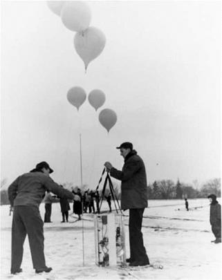
FIGURE 1.1 James Van Allen (left) and Leslie Meredith preparing one of Les’ instrument gondolas for launching on 26 January 1952. The gondola frame resting on the ground contained the three-counter telescope at its top, the airborne portion of the telemetering system in the center, and the batteries in the bottom. (Courtesy of the Department of Physics and Astronomy Van Allen Collection, The University of Iowa, Iowa City, Iowa.) |
1949.1112 The concept was further developed in discussions during that cruise by the two of them, along with George Halverson of the USN and Siegfried Frederick Singer (known widely as S. Fred Singer) of the University of Maryland. The basic approach was to lift small, inexpensive, military-surplus rockets by balloons to an altitude of the order of 11 miles before firing them. When fired, the rockets would already be above the densest portion of the atmosphere. By thus avoiding the dominating influence of aerodynamic drag in the lower atmosphere, a much higher altitude could be reached than if the rockets had been fired from the ground. The initial rockoons made it possible to carry payloads weighing 40 pounds to peak altitudes greater than 60 miles for a cost for the rocket and balloon of less than $1800 for each flight. That compared with about $25,000 for each ground-launched Aerobee and $450,000 for each larger Viking rocket.
OPENING SPACE RESEARCH
![]() Shipboard launching made the concept especially attractive and feasible for several reasons: (1) a ship can steam downwind to minimize the relative wind seen by the tethered balloon-rocket combination while the balloon is being inflated, (2) ships at sea can avoid populated areas and the possibility of damage by returning rockets that are fired in variable and largely uncontrollable directions, and (3) a wide range in geographic position can be covered from a single field installation.
Shipboard launching made the concept especially attractive and feasible for several reasons: (1) a ship can steam downwind to minimize the relative wind seen by the tethered balloon-rocket combination while the balloon is being inflated, (2) ships at sea can avoid populated areas and the possibility of damage by returning rockets that are fired in variable and largely uncontrollable directions, and (3) a wide range in geographic position can be covered from a single field installation.
The basic techniques and logistics of launching rockets from shipboard had already been worked out during the Aerobee firings from the USS Norton Sound. Launching rockoons from shipboard represented a straightforward extension of those practices, adding only the requirement for inflating and launching the large balloons. In view of the modest demands imposed on the ship by the rockoon operation, it was not necessary to schedule the ships for that exclusive purpose—the task was added for voyages already planned for other purposes. Thus, the incremental cost of the field support operations was kept very low.
The basic rockoon concept was reduced to practical form by Van Allen and Gottlieb, assisted by students Joseph Kasper and Ernest Ray, during late 1951 and 1952.13 1415
That first rockoon’s solid propellant propulsion unit was known as the Deacon. It was originally designed by the JPL in Pasadena, California, as a jet-assisted takeoff (JATO) rocket for launching military aircraft from short runways. The Deacon was about six and one-quarter inches in diameter and nine feet long and had a thrust of 5700 pounds during a three to five second burn. They were mass-produced by the Allegheny Ballistic Laboratory of the Hercules Power Company located in Cumberland, Maryland.
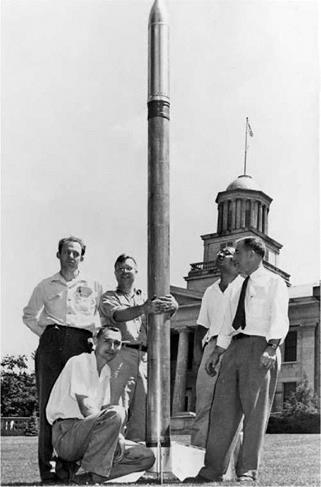
Van Allen and Gottlieb developed several modifications to the mass-produced JATO rockets. Extra large tail fins, fabricated in the State University of Iowa (SUI) instrument shop, were required to assure stable flight when the rockets were fired in the rarified upper atmosphere. A thin-walled, aluminum, pressure-tight instrument nose cone, with an adapter to fit it to the rocket case, was developed to house the instruments. Finally, a hook arrangement was devised for suspending the rockets beneath the balloons during their ascent. The Deacon rocket assembly that resulted is shown in Figure 1.2.
Two types of scientific instruments were prepared for the first rockoon field expedition. One, prepared by Les Meredith as a part of the work for his Ph. D. dissertation, contained a single GM counter to measure the absolute intensity of cosmic radiation above the effective atmosphere as a function of height and geomagnetic latitude. His instrument was somewhat similar electronically to that which he used for his earlier balloon flights, but with a single omnidirectional GM counter substituted for the three-counter directional detector. Since the resulting omnidirectional counting rate
|
CHAPTER 1 • SETTING THE STAGE AT THE UNIVERSITY OF IOWA 13
FIGURE 1.2 The Deacon rocket, modified for use as a rockoon, in front of the Old Capital Building on the University of Iowa campus. From the left, Melvin Gottlieb, Les Meredith (kneeling), Lee Blodgett, Robert Ellis (partly obscured), and James Van Allen. (Courtesy of the Department of Physics and Astronomy Van Allen Collection, The University of Iowa, Iowa City, Iowa.) |
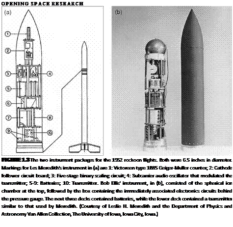
would be greater than the directional rate seen during the balloon flights, the new instrument required a pulse-scaling circuit to reduce the pulse rate to be transmitted to the ground. That electronic scaling circuit was adapted from a design by John A. Simpson at the University of Chicago. Five cascaded binary stages divided the counting rate from the GM counter by a factor of two to the fifth power, or 32. Most of the electronic circuits used the very rugged, low-power, and tiny Raytheon CK-5678 vacuum tubes that Van Allen had helped develop for the proximity fuses during WWII. The general arrangement of Meredith’s rockoon instrument is shown in Figure 1.3a.
 |
Special Publications 14
A second instrument type was prepared by Robert (Bob) A. Ellis Jr. It used a chamber to measure total cosmic ray ionization. His instrument, also shown in Figure 1.3b, drew heavily on Meredith’s designs and techniques, but he used a pulse – ionization chamber rather than a GM counter as the principal detector. Individual pulse amplitudes, rather than counting rates, were telemetered. The chamber was a six-inch diameter sphere of 0.010 inch thick copper with an axial Kovar collector wire supported by ceramic insulators and with guard rings to eliminate electrical leakage across the insulators. The chamber’s pulses were amplified and lengthened before transmission by a circuit that produced an output pulse whose length was proportional to the input pulse amplitude.
Design of the research instruments for the rockoon flights benefited greatly from Van Allen’s experience in developing the proximity fuses for artillery shells during WWII. Robust components and construction techniques were used to withstand the
CHAPTER 1 • SETTING THE STAGE AT THE UNIVERSITY OF IOWA 15
high initial acceleration and severe vibration of the rocket firings. Most of the vacuum tubes adopted from the proximity fuse program for our purposes were the superrugged, low-power, subminiature vacuum tubes identified as the Raytheon CK-5678. The larger 3A5 acorn tube that had been used in the transmitters for the balloon-borne instruments was found to be sufficiently rugged and was retained for the rockoon flights. The coils for the transmitters were hand-wound and adjusted for the proper frequency (74 MHz) and maximum power (one to two watts).
Testing procedures were remarkably simple and direct. Meredith recounted, “The only ‘G’ [acceleration] test was to put a working circuit board with its batteries on an arm on the drill press and see if it survived being spun. Only the ones that flew off and went flying across the lab failed.”16
Initial ground-launched tests of the rocket configuration (without the balloon or instruments) were made by Van Allen, Meredith, and Ellis at the U. S. Naval Ordnance Missile Test Facility at the White Sands Missile Range, New Mexico, during June and July 1952. Of three launches from the White Sands short tower, two flights were successful and demonstrated the rocket assembly’s mechanical ruggedness, flight stability, and performance. Two additional launchings of small rockets from a simulated balloon suspension rig verified the design of the coupling ring and hook, showing that the rocket’s line of flight would be within a few degrees of its static angle of suspension at the time of firing.
The first field expedition with Meredith’s and Ellis’ research instruments was on the U. S. Coast Guard icebreaker USCGC Eastwind during August and September 1952.17 18 The Iowa participants were Van Allen, Meredith, and technician Lee F. Blodgett. Ellis did not participate in the field exercise—Van Allen took charge of his instruments.
The icebreaker, under the command of Captain Oliver A. Peterson, progressed northward along the Davis Strait between Canada and Greenland, with its primary mission being to resupply the weather station at Alert Base on the northwestern shore of Ellesmere Island. The Iowa group and the balloon support team flew with their equipment from Westover Air Force Base in Massachusetts to join the ship at Thule in north Greenland. (The locations of those sites can be seen in Figure 2.13.) They were joined there by a group from New York University, who brought equipment for cosmic ray neutron measurements via balloons.
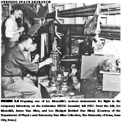
On board ship, the scientists were very ably assisted by Lieutenant Malcolm S. Jones from the ONR. The Iowa researchers set up their laboratory in a room below decks, as seen in Figure 1.4. The balloon crew arranged their equipment for inflating and launching the balloons on the ship’s helicopter deck. The ship departed Thule with the full complement of scientists and their gear on 29 July 1952, progressing
 |
16
farther northward on its primary supply mission to Alert Base. Incidentally, on that cruise, they set a new record of 508 miles for the closest approach to the North Pole by a ship under its own power.
After the supply delivery at Alert Base, the ship returned to the upper end of Baffin Bay, where, during the period 20 August through 4 September, the SUI scientists made their rockoon launches from the mouth of Murchison Sound, about 100 miles northwest of Thule.
Open-neck, thin-film, plastic Skyhook balloons, 55 feet in diameter and made by the General Mills Aeronautical Research Division in Minneapolis, Minnesota, were used to lift the approximately 210 pound rockets and instrumented nose cones to firing altitude. A small SUI-made rocket-firing gondola, containing a timer, barometric pressure switch, and firing batteries, was suspended from the rocket’s tail fins by a light cord so that the rocket would break away once it was fired. The balloons were filled with enough helium to give about 35 pounds more lift than the combined rocket, payload, firing gondola, and rigging weight. That produced a balloon rate of rise of about 800 feet per minute, thus requiring nearly an hour for the climb to the firing altitude of about 40,000 feet. To keep the rockets and instruments warm during the long balloon ascents through the cold stratosphere, the rocket bodies were
|
CHAPTER 1 • SETTING THE STAGE AT THE UNIVERSITY OF IOWA 17
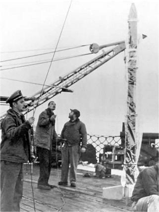
FIGURE 1.5 Launching a rockoon from the deck of the USCGC Eastwind on the 1952 expedition. The balloon had been filled, the rocket had been assembled, and preparations were being made to attach the load line to the rocket. From the left, Lieutenant Malcolm S. Jones, Les Meredith, and James Van Allen. (Courtesy of the Department of Physics and Astronomy Van Allen Collection, The University of Iowa, Iowa City, Iowa.) |
painted black to absorb solar radiation and were covered by transparent plastic shrouds spaced away from the bodies by Styrofoam rings to provide additional warming by the greenhouse effect.
Preparations for launches were made by the Iowa University team, with very effective help by the ship’s officers and men. Lieutenant Jones installed and armed the rocket igniters. The balloon inflation and launching operations were conducted by J. R. Smith and J. Froelich from General Mills. Figure 1.5 shows the action on the ship’s deck during final preparations for one of the launches.
Seven flights were attempted, and all of the balloons performed admirably. However, the first two rockets, both of which carried Meredith’s instruments, failed to ignite. On the second of those flights, data were received from the instrument for about 10 hours as it floated at balloon altitude, thus verifying the effectiveness of
OPENING SPACE RESEARCH
![]() the payload temperature control arrangement and the adequacy of the battery packs. Those two initial failures were blamed on failure of the pressure switches due to their low temperature, and sealed cans of fruit juice were added to the firing gondolas to help keep the switches warmer during the balloon ascent. That technique was validated by a balloon test flight and was adopted for the rest of the rockoon launches.
the payload temperature control arrangement and the adequacy of the battery packs. Those two initial failures were blamed on failure of the pressure switches due to their low temperature, and sealed cans of fruit juice were added to the firing gondolas to help keep the switches warmer during the balloon ascent. That technique was validated by a balloon test flight and was adopted for the rest of the rockoon launches.
The third rockoon flight, on 28 August 1952 (SUI flight number 3),19 was the world’s first ballistically successful rockoon flight. The rocket fired at an altitude of 38,000 feet, 55 minutes after release of the ensemble from shipboard. The rocket reached an estimated summit altitude of about 200,000 feet, or nearly 38 miles. The flight failed, however, to produce useful data from the instrument.
The remaining four rocket flights, made near 88 degrees north geomagnetic latitude, were also ballistically successful, with the best performance being a flight to over 55 miles height. Flights 4 and 5 carried Les’ instruments, while flights 6 and 7 carried the instruments that had been built by Ellis.
The ship returned to Thule on 5 September 1952, and the researchers returned from there to the United States by Air Force aircraft. As they returned to the campus that September, the Iowans were delighted that the practicality and effectiveness of the new low-cost rockoon technique had been convincingly demonstrated. Processing and analyzing the data from those flights occupied the scientists’ attention for some months after their return.
Van Allen prepared a paper for presentation to the American Physical Society in November 1952. That paper’s main purpose was to provide an overall summary of then-existing knowledge of the low-rigidity end of the primary cosmic ray spectrum. In the second half of that paper, he made use of the data from the two successful rockoon flights of Les Meredith’s instrument. One conclusion was that the new measurements confirmed and extended previous evidence for the marked flattening of the integral primary cosmic ray spectrum below a magnetic rigidity of about 1.5 x 10⁹ volts.20
Van Allen reported separately that flights 6 and 7 of Ellis’ instruments produced good values of total cosmic ray ionization up to about 40 miles altitude.21
Meredith used the results from his two successful 1952 flights, combined with the data from a flight made during the following summer, for his dissertation.22 The flight data from those three flights spanned the range of geomagnetic latitude from about 88 to 54 degrees. His dissertation reported a value of unidirectional particle intensity averaged over the upper hemisphere of 0.48 (cm2 sec sterad)-1. He further stated that his measurements were consistent with a complete or nearly complete absence of primary cosmic ray particles of magnetic rigidity less than 1.7 x10⁹ volts. (It should be noted for the sake of completeness that later, more sensitive and discriminating instruments did provide quantitative measurements of spectra at lower rigidities.23,24,25)
CHAPTER 1 • SETTING THE STAGE AT THE UNIVERSITY OF IOWA 19


