Cockpit Instrumentation
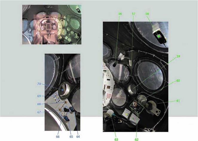
Inside the cockpit, mixed between the circular windows, ports, door, and escape hatch, the pilot had all the instruments and controls he needed for all the various phases of flight. Figures 6.15 to 6.17 show views of the instruments and controls at the front of the cockpit, to the left side of the pilot, and to the right side of the pilot, respectively. The instruments and controls are identified by their numbered callouts given from these figures.
The pilot used the control stick (33) and the rudder pedals (7 and 12) to fly subsonically and to maneuver using the RCS (15,38, and 41).
But for supersonic flight, trims (31,35, and 36) and backups (55) were used. The controls for the rocket engine included switches and a timer (34, 42, and 49—52).The feather was operated using valves and levers (1, 3, 39, 40, 43, and 44).
Cameras on the tail, on the fuselage, and in the cockpit (56) provided video that was also an important source of data during flight testing. Mission Control used one of the cameras to monitor the feather and rocket engine in real-time. Two of the more unexpected things found in the cockpit were the ping-pong ball (8), which was used to provide a good visual during weightlessness, and the “Q-tip” (63), which the pilot used to wipe down excess moisture from the windows.
The controls for the ECS (13, 16, 17, and 64-69), battery (18—22), landing gear (45 and 53), radios (30), and other systems were also close at hand. However, important instruments like the airspeed indicator, Machmeter, altimeter, and energy altitude predictor were all displayed on the FDD of theTONU (11), and airspeed and altitude were also backed up on the Dynon (10).

Ґ Л
Fig. 6.11. One of the components of the Tier One navigation unit (TONU) was the flight director display (FDD). Like the glass cockpit of an airliner, the FDD showed many of the important instruments and readouts used by the pilot to fly SpaceShipOne. An initialize mode of the FDD is shown with SpaceShipOne lined up on Runway 30 of Mojave Airport. Mojave Aerospace Ventures LLC, provided courtesy of Scaled Composites
Fig. 6.12. As SpaceShipOne rockets to space, a boost mode is shown on the FDD. By closing together the red circle and green circle, the pilot achieved optimum trajectory. The pilot could also view the status of the rocket engine and oxidizer tank. Mojave Aerospace Ventures LLC, provided courtesy of Scaled Composites
Fig. 6.13. The FDD shows a reentry mode before SpaceShipOne returns to Earth’s atmosphere. The position of the feather, the operation of the reaction control system (RCS), and the condition of their pressurization sources are displayed. Mojave Aerospace Ventures LLC, provided courtesy of Scaled Composites
Fig. 6.14. After reentry and the feather is retracted, SpaceShipOne glides back to Mojave Airport. The test pilot used a glide mode on the FDD to help ensure SpaceShipOne reached the runway at correct position and speed. Mojave Aerospace Ventures LLC, provided courtesy of Scaled Composites
к_______________________________________ )
|
|
|
Feather bottle low: A and В
Wing against stops and wing ТЕ locked
down indicators
Feather position
Launch separation controller
Spaceship “Armed” indicator
Mothership “Armed” indicator
Left rudder pedal
Ping-pong ball
Backup GPS navigation display Dynon backup altitude indicator FDD (flight director display) of theTONU (Tier One navigation unit)
Right rudder pedal Cabin altitude gauge
Landing pattern attitudes: normal and emergency (gear down)
RCS bottle pressure warning lights: A and В ECS bottle pressure warning lights: A and В Cabin pressure low warning light Battery voltage Bus tie A battery Selector switches В battery
Video transmit power TONU power
Trim circuit breakers: left stabilizer, right stabilizer, yaw, and backup trim Backup rate display
Stabilizer boost Damper heat
Circuit breaker panel indicators Communication/navigation panel: two radios, transponder, and intercom selector panel Pitch trim
Red button not used Pilot roll /pitch control stick Rocket motor fire Roll trim Yaw trim
FDD page control switches

RCS A enable switches Feather actuator Feather unlock RCS В enable switches Rocket motor arm
Feather lock pressure valves: A and В (the yellow feather lock valve also doubles as gear down emergency assist)
Feather actuator pressure valves: A and В
Landing gear handle
Nose cone release handle
Nitrous oxide dump valve
Backup dump (through main valve)
Rocket motor controller power: A and В buses Rocket motor controller reset
Motor armed indicator, main oxidizer valve commanded open indicator, and nitrogen pressure low indicator Rocket motor burn time controller Landing gear down indicators: left, nose, and right Lamp test
Backup trim (stabilizer) panel
Lipstick camera, forward cabin (focused on pilot)
Dry air feed line (vents between window panes to prevent fogging) GPS antenna (attached to window)
4-inch opening for fine cabin pressure relief valve
Fine cabin pressure relief valve (this is the storage location)
Emergency cabin pressure dump port (this is the storage location)
Oxygen control panel
“Q-tip”
Secondary cabin pressure bottle valve
Primary cabin pressure bottle valve
Pressure regulator and gauge
Defog control valve (for between window panes)
Cabin make-up air
Dehumidifier fans and CO2 scrubber fan switches 4-inch opening for emergency cabin pressure dump port
photo by Eric Long and Mark Avion, National Air and Space Museum, Smithsonian Institution

|
||||||||||
|
||||||||||
|


