Fuselage and Composite Structures
The construction of SpaceShipOne really began with the building of the fuselage. Without its wings and tail attached to the fuselage, SpaceShipOne looks like a stubby little rocket. Figure 4.5 shows the crew compartment in the forward section of the fuselage, the oxidizer tank in the middle section, the rounded pressure bulkhead that separates the crew compartment from the oxidizer tank, and the rocket engine in the aft section. The maximum outer diameter of the cylindrical
|
|
г ^
Fig. 4.5. The cutaway drawing shows the crew positions in the cockpit of SpaceShipOne. A pressure bulkhead separates the crew from the rest of the rocket engine. The oxidizer tank mounted at the center of the fuselage has the rocket engine CTN (case/throat/nozzle) attached directly to it. Mojave Aerospace Ventures LLC, provided courtesy of Scaled Composites
V_____________________________________ )
|
|
f >
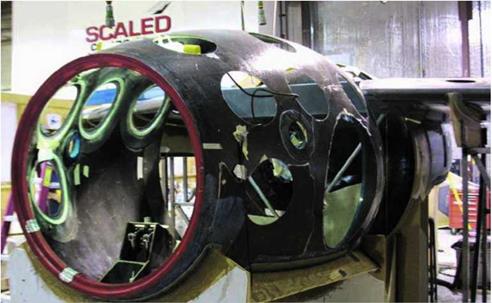
Fig. 4.6. A first step in the assembly was to build the carbon fiber/epoxy composite subassemblies that made up the fuselage. The subassemblies were bonded together, except for the nose cone, which was a detachable emergency escape hatch. Mojave Aerospace Ventures LLC, photograph by Scaled Composites
V__________________ )
fuselage is 60 inches (152 centimeters). It is a monocoque design, which means that the fuselage hull provides most of the structural support and load bearing for the spacecraft. However, the rocket engine obviously exerts a tremendous amount of force. So, the oxidizer tank is actually a very important structural member as well.
SpaceShipOne was put together much the same way a small plastic model airplane is put together. Beginning with a bunch of individual parts, they are assembled piece by piece. Woven layers, also called plies, of carbon fiber and epoxy were the primary materials used to make most of the lightweight composite parts of SpaceShipOne. These parts were used to build the fuselage, the wings, and the tail booms.
The whole process began by designing the parts using three – dimensional computer-aided design (CAD). The designs were then fed into an automated computer numerical control (CNC) machine to carefully shape the parts by whittling down foam blocks. Even though these foam parts precisely resembled the actual composite parts, they did not share the same strength, durability, resilience, and imperviousness to temperature. The foam parts were used to create molds that would then be used to create the actual composite parts to build SpaceShipOne.
After the molds were created, lay-up began. Here the composite material was built up layer by layer. Once enough material was added and the layers were to the proper thickness, the parts were vacuum-bagged and oven-cured. The vacuum-bagging process is basically what it sounds like. A part is covered with an airtight bag, which is evacuated by a pump. What this does is remove air from in between the layers and volatile compounds that are in the epoxy, which have become unwanted byproducts. The more thoroughly they are removed, the stronger the composite will be. The oven-curing enables the epoxy to properly set and achieve the desired properties. After the parts for SpaceShipOne were cured, assembly began.
Although the materials may have changed, the building technique was not unlike that used to build European sailplanes over the past forty or fifty years.
The primary structure of the fuselage is made up of only a few very large subassemblies. Figure 4.6 shows the nose cone and cabin section. The subassemblies have edges that fit to one another. They are then fastened with a jig and chemically bonded together. The subassemblies
 r ; л
r ; л
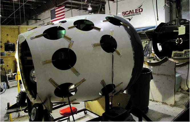
Fig. 4.7. Piece by piece, the exterior of SpaceShipOne took shape, like the building of a plastic model airplane. As construction proceeded, the wings were attached to the fuselage, and all the wiring, plumbing, linkages, and other components were installed inside. Mojave Aerospace Ventures LLC, photograph by David M. Moore
v________ J

ґ
Fig. 4.8. Because the cockpit was pressurized and SpaceShipOne faced extreme conditions in space, the walls of the fuselage provided double containment. In between the "shell within a shell" was an insulating layer that also improved the structural strength of the fuselage. Mojave Aerospace Ventures LLC, photograph by David M. Moore
V__________________________________________________________________________________________
|
|
f ^
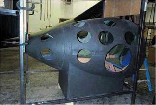
Fig. 4.9. This photograph shows the early stages of construction for the aft section of SpaceShipOne. A pressure bulkhead will be put in place at about the location of the opening in the fuselage to separate the oxidizer tank from the cockpit. Mojave Aerospace Ventures LLC, photograph by David M. Moore
V____________________________________ J
together form the inner hull or shell of SpaceShipOne. This inner shell is still not strong enough to support the spacecraft.
The nose cone is attached to the rest of the fuselage a little differently. The nose cone is the primary escape hatch. Its edge is keyed so that it can lock and unlock from the fuselage with a quick little turn.
Figure 4.7 shows the cabin section that is forward of the pressure bulkhead in various stages of construction. Figure 4.8 shows the top of the cabin section after even more assembly, and figure 4.9 shows the aft section where the wings mount.
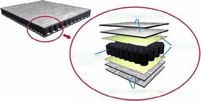
The next step in building the fuselage was to add a core of honeycomb material on top of the inner shell. Nomex, made by DuPont, was used as the honeycomb core. Not only is the honeycomb core lightweight, it offers high strength and it is heat and fire resistant. The honeycomb core, however, cannot serve as the outer layer. It needs further covering. So, panels called skins, manufactured using this composites process, were attached to the honeycomb core. The fuselage is a shell within a shell. The process of adding successive layers creates what is known as a sandwich structure, as the fuselage hull is viewed in cross-section. Figure 4.10 shows an example of a sandwich structure. Another way to look at this is that the fuselage hull is a thick composite made up of several thin composites.
 Honeycomb Sandwich Structure
|
|
|
|
|
|
|
|
|
|
![]()
After the assembly of the composite parts, SpaceShipOne resembled a spacecraft, but the job was far from over. “The hard part is stuffing all the systems in it and making sure that they are mounted properly,” Rutan said.
Initially the fuselage ended at the throat of the rocket-engine nozzle. During the flight tests, a fairing was added to extend the fuselage to the rim of the nozzle in order to improve aerodynamics.


