Seventh Story
Gust response, speed, weight, these are fixed. We are left with at, lift slope, the slope of the curve that tracks variations in lift against changes in angle of attack. We are left with this and the hope that its slope will be flat. But there is more. For instance, the stories are about transonic flight: How will the wing behave at roughly the speed of sound? And there are other questions; for example, how will it act at low speeds? So here’s another complexity, one that I earlier chose to ignore. This is the quote again, from the English Electric brochure: ‘‘The essential design compromise implied by O. R.339 is between high speed flight at low level, and operation from short airfields. The intermediate choice between a high-wing loading with a low aspect ratio to minimise gust response, and a large wing area assisted by high lift devices to provide plenty of lift at low speeds, must be resolved’’ (English Electric/Short Bros. 1958, 2.1.8). So gust response is important, but so too is take-off—which requires plenty of lift at low speeds. The brochure says:
Another convenient parameter is one which gives an indication of the relative response to gusts while achieving a given takeoff distance. This may be expressed as P say, where
![]() P =
P =
lf
where CLf is the maximum trimmed CL, flaps down, in touchdown attitude. P must be a minimum for good design. (English Electric/Short Bros. 1958, 2.1.9)
We’ve met these terms before. A reminder:
— CL is lift coefficient, roughly the lifting force of a wing: here, the lifting force of the wing as the plane comes into land with its flaps down.
—And at is lift curve slope, change in lift against change in angle of attack.
P therefore quantifies a hybrid relationship, the hope that it is possible to find a wing with low transonic gust response and high lift at landing.
But how to find a wing of the right shape? Of the right planform. This is a technical term and it is one of some importance. The brochure continues: ‘‘In the absence of comprehensive data on the effects of flaps on low aspect ratio wings, a comparison replacing CLf by CLmax indicated that delta wings were superior to trapezoidal and swept wings’’ (English Electric/Short Bros. 1958, 2.1.9). The terms here?
— CLmax is the aerodynamicist’s way of designating maximum lift. —Low aspect ratio wings (a reminder) are wings that are short in relation to their area.
—Delta wings are triangular, like those of a paper dart.
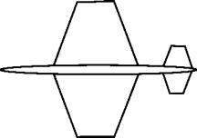
—And a trapezoidal wing is shaped like a trapezium. That is, though the wing tip is parallel to the root of the wing, the leading and trailing edges converge toward that tip.
The paragraph then discusses planform:
Since it was thought possible that by using leading edge flaps on trapezoidal wings, higher values of CLf might be obtained
than those from delta wings, wind tunnel tests were carried out using a trapezoidal wing-body combination. In the event, these tests confirmed that the delta gave higher values of CLf. The delta planform was also expected to have better transonic characteristics, and again high speed tests in our 18" tunnel on a family of aspect ratio = 2 planforms confirmed the unsatisfactory characteristics of trapezoidal wings, with sudden large aerodynamic centre movements at transonic speeds. This confirmed the choice of the delta planform. (English Electric/Short Bros. 1958, 2.1.9)
A further explanation. This time about aerodynamic center. As it moves through the air a wing lifts, but it does so by differing amounts in different parts of the wing. It’s useful to simplify, however, and sum the effect of all these separate parts to create something called the aerodynamic center. Roughly, this is the place in the wing where the
 FIGURE 5.7 Trapezoidal Wings
changes in overall lift occur as it flies faster or slower or its angle of attack changes. Above stalling speed the aerodynamic center doesn’t shift much. At subsonic speeds it’s about one quarter back from the leading edge for most wings. But at around the speed of sound the aerodynamic center tends to move backward. This isn’t a disaster unless it moves quickly and jerkily, in which case the aircraft can be difficult to control—which would take us back to pilot sweat and fear.
So the English Electric engineers were looking at two things. One was aerodynamic center. Here the trapezoidal wing was a problem because the movement was ‘‘sudden’’ and ‘‘large.’’ The delta wing was better. The second was CLmax (max, here, means maximum lift). Here
 |
 |
there was a surprise: the delta wing was better again. On both counts the trapezoidal wing came off worse.


