PROPELLANT LEVEL MONITORING SUBSYSTEM
The propellant level monitoring subsystem checks the level of propellants in both tanks to provide checkpoints for the sensors used in the propellant utilization and loading subsystems and to monitor propellant levels during firing. These functions are performed by sensors mounted on continuous Stillwells adjacent or parallel to the full-length capacitance probes in each tank. There are 14 sensors on each Stillwell to indicate various levels in the tanks.
ULLAGE MOTORS
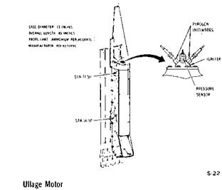
The solid propellant ullage motors are used to provide artificial gravity by momentarily accelerating the second stage forward after first stage burnout. This moment of forward thrust is required in the weightless environment of outer space to make certain that the liquid propellant is in proper position to be drawn into the pumps prior to starting of the second stage engines.
|
SATURN V NEWS REFERENCE
|
|
Eight ullage motors are utilized on the stage where they are attached around the periphery of the interstage structure between the first and second stages. Each ullage motor measures 12.5 inches in diameter by 89 inches long and each provides 22,500 pounds of thrust for approximately 4 seconds. The motors utilize Flexadyne solid propellant in a formulation developed specifically to provide high performance and superior mechanical properties under operating conditions encountered in space. Ullage motor nozzles are canted 10 degrees to reduce exhaust impingement against the interstage structure.
THERMAL CONTROL SYSTEM
Thermal control is provided by a ground-operated system which maintains proper temperatures for the equipment containers in the forward and aft skirt areas. Tempered air is used to cool the containers before propellant loading. With preparation for loading, the air is changed to nitrogen for container inerting and heating. Separate thermal control systems are provided for the forward and aft skirt areas. Each of the units contains a single manifold connected to each container, individual fixed-flow orifices, and individual relief holes from each container. Container insulation and thermal inertia preclude excessive temperature changes.


