PROPELLANT FEED CONTROL SYSTEM
The propellant feed system transfers LOX and fuel from the propellant tanks into the pumps which discharge into the high-pressure ducts leading to the gas generator and the thrust chamber. The system consists of two oxidizer valves, two fuel valves, a bearing coolant control valve, two oxidizer dome purge check valves, a gas generator and pump seal purge check valve, turbopump outlet lines, orifices, and lines connecting the components. High-pressure fuel is supplied from the propellant feed system of the engine to the vehicle-contractor-supplied thrust vector control system.
|
|
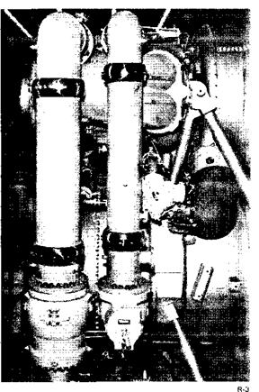
Propellant Feed…. The main LOX valve and high-pressure line
are shown at left. At right are the main fuel valve and high- pressure line.
Oxidizer Valves
Two identical oxidizer valves, designated No. 1 and No. 2, control LOX flow from the turbopump to the thrust chamber oxidizer dome and sequence the hydraulic fuel to the opening port of the gas generator valve. When the valves are in the open position at rated engine pressures and flowrates, neither will dose if the hydraulic fuel opening pressure is lost. Each of the oxidizer valves is a hydraulically actuated, pressure-balanced, poppet type, and contains a mechanically actuated sequence valve. A spring-loaded gate valve permits reverse flow for recirculation of the hydraulic fluid with the propellant valves in the closed position, but prevents fuel from passing through until the oxidizer valve is open 1*3.4 per cent. As the oxidizer valve reaches this position, the piston shaft opens the gate, allowing fuel to flow through the sequence valve, which in turn opens the gas generator valve.
|
R-6 |
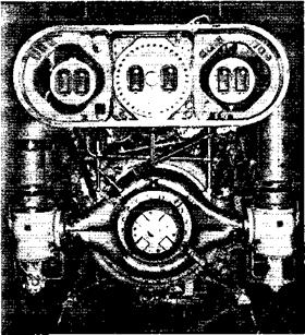
LOX Distribution -Oxidizer is distributed by the LOX dome (lower center). Main LOX valves are shown at left and right with the engine interface panel above.
A position indicator provides relay logic in the engine electrical control circuit and provides instrumentation for recording movement of the oxidizer valve poppet.
The two oxidizer dome purge check valves, mounted on each of the oxidizer valves, allow purge gas to enter the oxidizer valves, but prevent oxidizer from
entering the purge system.
Fuel Valves
Two identical fuel valves, designated No. 1 and No. 2, are mounted 180 degrees apart on the thrust chamber fuel inlet manifold and control the flow of fuel from the turbopump to the thrust chamber. When the valves are in the open position at rated engine pressures and flowrates, they will not dose if hydraulic fuel pressure is lost.
Position indicators in the fuel valves provide relay logic in the engine electrical control circuit and instrumentation for recording movement of the
valve poppets.


