FIRST STAGE
FIRST STAGE DESCRIPTION
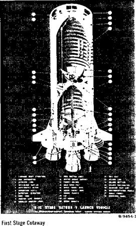
The Saturn V first stage (S-IC) is a vertical grouping of five cylindrical major components and a cluster of five F-l rocket engines. Upward from the engines are the thrust structure, fuel tank, intertank structure, LOX tank, and forward skirt. The total stage measures 138 feet in height and 33 feet in diameter without its fins. It weighs 6,100,000 pounds at liftoff and delivers 7.5 million pounds of thrust.
|
|
FIRST STAGE FABRICATION AND ASSEMBLY
Design, assembly, and test of the first stage booster are the prime tasks being performed by The Boeing Company at the Marshall Space Flight Center, Huntsville, Ala., the Michoud Assembly Facility, New Orleans, La., and the Mississippi Test Facility in southwestern Mississippi. Launch operations support is provided by the Boeing Atlantic Test
Center, Kennedy Space Center, Fla. Contractor suppliers lend support for much of the first stage fabrication. Several ground test stages were completed before manufacture of a series of flight stages was begun. Huntsville and Michoud installations shared responsibility for assembly of four ground test stages and the first two flight stages. All other flight stages are being assembled at Michoud.
|
B-7031-10 |
Assembled First Stage
Thrust Structure
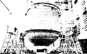
The thrust structure is the heaviest of first stage components, weighing 24 tons. It is 33 feet in diam-
|
B-10648-5 |
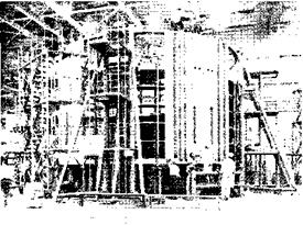
Base Assembly—Workmen cover the thrust structure shell with aluminum skin.
|
SATURN V NEWS REFERENCE
eter and about 20 feet tall with these major components: the lower thrust ring assembly, the center engine support assembly, four holddown posts, engine thrust posts, an upper thrust ring assembly, intermediate rings, and skin panel assemblies.
The upper ring provides stability for the corrugated skins around the structure. Four F-l engines are mounted circumferentially upon the thrust posts and the fifth upon the center engine support assembly. The center engine remains rigid while the others gimbal or swivel, allowing the stage to be guided.
A base heat shield protects internal parts from engine heat, and four holddown posts restrain the vehicle while the engines build up power for liftoff.
The thrust structure supports the entire vehicle weight and distributes the forces of the engines.
|
B-6018-7 |
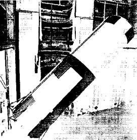
Thrust Structure—The 24-ton base of the booster is being taken to the Vertical Assembly Building for mating with other first stage components.
Fuel Tank
The fuel tank holds 203,000 gallons of kerosene and encloses a system of five LOX tunnels.
The tank, weighing more than 12 tons dry, is capable of releasing 1,350 gallons of kerosene per second to the engines through 10 fuel-suction lines. The LOX tunnels carry liquid oxygen from the LOX tank, through the fuel tank, and to the engines.
Bound by eight aluminum skin panels, the fusion – welded fuel tank assembly is 33 feet in diameter and 44 feet tall. Ends are enclosed by ellipsoidal bulkheads.
The bulkheads consist of eight pie-shaped gores mated with a polar cap to form a dome shape.
Connecting links between the skin rings and bulkheads are circular bands known as the Y-rings. The Y-rings are used on both propellant tanks and link them to other segments of the booster at final
assembly.
|
В-*>4Ь9-20 |
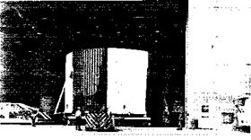
Fuel Tank—Kerosene is fed to the engines at 1,300 gallons per second from this 203,000 gallon tank. Here the finished tank is being lowered onto its transporter.
|
B-5622-4 |
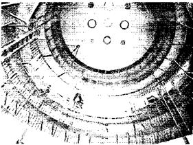
Inside View—The fuel tank contains horizontal baffles, which are designed to prevent sloshing of fuel.
|
B-4780-6 |
Fuel Tank Assembly – Workmen weld the base of the 27-inch – high Y-ring to the cylindrical segment of the fuel tank. This ring joins the tank sides to the dome and to the intertank structure.


