Preludes: Asset and Lifting Bodies
At the end of the 1950s, ablatives stood out both for the ICBM and for return from space. Insulated hot structures, as on Dyna-Soar, promised reusability and
lighter weight but were less developed.
 As early as August 1959, the Flight Dynamics Laboratory at Wright-Patter – son Air Force Base launched an in-house study of a small recoverable boost-glide vehicle that was to test hot structures during re-entry. From the outset there was strong interest in problems of aerodynamic flutter. This was reflected in the concept name: ASSET or Aerother – modynamic/elastic Structural Systems Environmental Tests.
ASSET won approval as a program
late in January 1961. In April of that
year the firm of McDonnell Aircraft,
which was already building Mercury
capsules, won a contract to develop the
ASSET flight vehicles. Initial thought
had called for use of the solid-fuel Scout
as the booster. Soon, however, it became. . ,
АЬЬЫ, showing peak temperatures, clear that the program could use the (u. S. Air Force)
Thor for greater power. The Air Force
had deployed these missiles in England. When they came home, during 1963, they became available for use as launch vehicles.
ASSET took shape as a flat-bottomed wing-body craft that used the low-wing configuration recommended by NASA-Langley. It had a length of 59 inches and a span of 55 inches. Its bill of materials closely resembled that of Dyna-Soar, for it used TZM to withstand 3,000°F on the forward lower heat shield, graphite for similar temperatures on the leading edges, and zirconia rods for the nose cap, which was rated at 4,000°F. But ASSET avoided the use of Rene 4l, with cobalt and columbium alloys being employed instead.1
ASSET was built in two varieties: the Aerothermodynamic Structural Vehicle (ASV), weighing 1,130 pounds, and the Aerothermodynamic Elastic Vehicle (AEV), at 1,225 pounds. The AEVs were to study panel flutter along with the behavior of a trailing-edge flap, which represented an aerodynamic control surface in hypersonic flight. These vehicles did not demand the highest possible flight speeds and hence flew with single-stage Thors as the boosters. But the ASVs were built to study materials and structures in the re-entry environment, while taking data on temperatures, pressures, and heat fluxes. Such missions demanded higher speeds. These boost – glide craft therefore used the two-stage Thor-Delta launch vehicle, which resembled
the Thor-Able that had conducted nose-cone tests at intercontinental range as early as 1958.2
The program conducted six flights, which had the following planned values of range and of altitude and velocity at release:
|
Asset Flight Tests
Source: Hallion, Hypersonic, pp. 505, 510-519. |
Several of these craft were to be recovered. Following standard practice, their launches were scheduled for the early morning, to give downrange recovery crews the maximum hours of daylight. This did not help ASV-1, the first flight in the program, which sank into the sea. Still, it flew successfully and returned good data. In addition, this flight set a milestone. In the words of historian Richard Hallion, “for the first time in aerospace history, a lifting reentry spacecraft had successfully returned from space.”3
ASV-2 followed, using the two-stage Thor-Delta, but it failed when the second stage did not ignite. The next one carried ASV-3, with this mission scoring a double achievement. It not only made a good flight downrange but was successfully recovered. It carried a liquid-cooled double-wall test panel from Bell Aircraft, along with a molybdenum heat-shield panel from Boeing, home of Dyna-Soar. ASV-3 also had a new nose cap. The standard ASSET type used zirconia dowels, 1.5 inches long by 0.5 inch in diameter, that were bonded together with a zirconia cement. The new cap, from International Harvester, had a tungsten base covered with thorium oxide and was reinforced with tungsten.
A company advertisement stated that it withstood re-entry so well that it “could have been used again,” and this was true for the craft as a whole. Hallion writes that “overall, it was in excellent condition. Water damage…caused some problems, but not so serious that McDonnell could not have refurbished and reflown the vehicle.” The Boeing and Bell panels came through re-entry without damage, and the importance of physical recovery was emphasized when columbium aft leading edges showed significant deterioration. They were redesigned, with the new versions going into subsequent ASV and AEV spacecraft.4
The next two flights were AEVs, each of which carried a flutter test panel and a test flap. AEV-1 returned only one high-Mach data point, at Mach 11.88, but this sufficed to indicate that its panel was probably too stiff to undergo flutter. Engineers made it thinner and flew a new one on AEV-2, where it returned good data until it failed at Mach 10. The flap experiment also showed value. It had an electric motor that deflected it into the airstream, with potentiometers measuring the force required to move it, and it enabled aerodynamicists to critique their theories. Thus, one treatment gave pressures that were in good agreement with observations, whereas another did not.
ASV-4, the final flight, returned “the highest quality data of the ASSET program,” according to the flight test report. The peak speed of 19,400 feet per second, Mach 18.4, was the highest in the series and was well above the design speed of
18,0 feet per second. The long hypersonic glide covered 2,300 nautical miles and prolonged the data return, which presented pressures at 29 locations on the vehicle and temperatures at 39. An onboard system transferred mercury ballast to trim the angle of attack, increasing L/D from its average of 1.2 to 1.4 and extending the trajectory. The only important problem came when the recovery parachute failed to deploy properly and ripped away, dooming ASV-4 to follow ASV-1 into the depths of the Atlantic.5
On the whole, ASSET nevertheless scored a host of successes. It showed that insulated hot structures could be built and flown without producing unpleasant surprises, at speeds up to three-fourths of orbital velocity. It dealt with such practical issues of design as fabrication, fasteners, and coatings. In hypersonic aerodynamics, ASSET contributed to understanding of flutter and of the use of movable control surfaces. The program also developed and successfully used a reaction control system built for a lifting re-entry vehicle. Only one flight vehicle was recovered in four attempts, but it complemented the returned data by permitting a close look at a hot structure that had survived its trial by fire.
A separate prelude to the space shuttle took form during the 1960s as NASA and the Air Force pursued a burgeoning interest in lifting bodies. The initial concept represented one more legacy of the blunt-body principle of H. Julian Allen and Alfred Eggers at NACA’s Ames Aeronautical Laboratory. After developing this principle, they considered that a re-entering body, while remaining blunt to reduce its heat load, might produce lift and thus gain the ability to maneuver at hypersonic speeds. An early configuration, the M-l of 1957, featured a blunt-nosed cone with a flattened top. It showed some capacity for hypersonic maneuver but could not glide subsonically or land on a runway. A new shape, the M-2, appeared as a slender half-cone with its flat side up. Its hypersonic L/D of 1.4 was nearly triple that of the M-l. Fitted with two large vertical fins for stability, it emerged as a basic configuration that was suitable for further research.6
Dale Reed, an engineer at NASA’s Flight Research Center, developed a strong interest in the bathtub-like shape of the M-2. He was a sailplane enthusiast and a builder of radio-controlled model aircraft. With support from the local community of airplane model builders, he proceeded to craft the M-2 as a piloted glider. Designating it as the M2-F1, he built it of plywood over a tubular steel frame. Completed early in 1963, it was 20 feet long and 13 feet across.
It needed a vehicle that could tow it into the air for initial tests. However, it produced too much drag for NASA’s usual vans and trucks, and Reed needed a tow car with more power. He and his friends bought a stripped-down Pontiac with a big engine and a four-barrel carburetor that reached speeds of 110 miles per hour. They took it to a funny-car shop in Long Beach for modification. Like any other flightline vehicle, it was painted yellow with “National Aeronautics and Space Administration” on its side. Early tow tests showed enough success to allow the project to use a C-47, called the Cooney Bird, for true aerial flights. During these tests the Cooney Bird towed the M2-F1 above 10,000 feet and then set it loose to glide to an Edwards AFB lakebed. Beginning in August 1963, the test pilot Milt Thompson did this repeatedly. Reed thus showed that although the basic M-2 shape had been crafted for hypersonic re-entry, it could glide to a safe landing.
As he pursued this work, he won support from Paul Bikle, the director of NASA Flight Research Center. As early as April 1963, Bikle alerted NASA Headquarters that “the lifting-body concept looks even better to us as we get more into it.” The success of the M2-F1 sparked interest within the Air Force as well. Some of its officials, along with their NASA counterparts, went on to pursue lifting-body programs that called for more than plywood and funny cars. An initial effort went beyond the M2-F1 by broadening the range of lifting-body shapes while working to develop satisfactory landing qualities.7
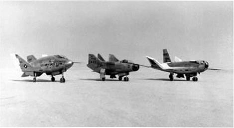
NASA contracted with the firm of Northrop to build two such aircraft: the M2- F2 and HL-10. The M2-F2 amounted to an M2-F1 built to NASA standards; the HL-10 drew on an alternate lifting-body design by Eugene Love of NASA-Langley. This meant that both Langley and Ames now had a project. The Air Force effort, the X-24A, went to the Martin Company. It used a design of Frederick Raymes at the Aerospace Corporation that resembled a teardrop fitted with two large fins.
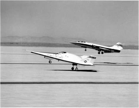
All three flew initially as gliders, with a B-52 rather than a C-47 as the mother ship. The lifting bodies mounted small rocket engines for acceleration to supersonic
speeds, thereby enabling tests of stability and handling qualities in transonic flight. The HL-10 set records for lifting bodies by making safe approaches and landings at Edwards from speeds up to Mach 1.86 and altitudes of 90,000 feet.8
Acceptable handling qualities were not easy to achieve. Under the best of circumstances, a lifting body flew like a brick at low speeds. Lowering the landing gear made the problem worse by adding drag, and test pilots delayed this deployment as long as possible. In May 1967 the pilot Bruce Peterson, flying the M2-F2, failed to get his gear down in time. The aircraft hit the lakebed at more than 250 mph, rolled over six times, and then came to rest on its back minus its cockpit canopy, main landing gear, and right vertical fin. Peterson, who might have died in the crash, got away with a skull fracture, a mangled face, and the loss of an eye. While surgeons reconstructed his face and returned him to active duty, the M2-F2 underwent surgery as well. Back at Northrop, engineers installed a center fin and a roll-control system that used reaction jets, while redistributing the internal weights. Gerauld Gentry, an Air Force test pilot, said that these changes turned “something I really did not enjoy flying at all into something that was quite pleasant to fly.”9
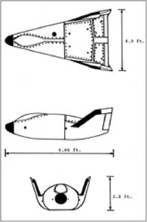
The manned lifting-body program sought to turn these hypersonic shapes into aircraft that could land on runways, but the Air Force was not about to overlook the need for tests of their hypersonic performance during re-entry. The program that addressed this issue took shape with the name PRIME, Precision Recovery Including Maneuvering Entry. Martin Marietta, builder of the X-24A, also developed the PRIME flight vehicle, the SV-5D that later was referred to as the X-23- Although it was only seven feet in length, it faithfully duplicated the shape of the X-24A, even including a small bubble-like protrusion near the front that represented the cockpit canopy.
PRIME complemented ASSET, with both programs conducting flight tests of boost-glide vehicles. However, while ASSET pushed the state of the art in materials and hot structures, PRIME used ablative thermal protection for a more straightforward design and emphasized flight performance. Accelerated to near-orbital velocities by Atlas launch vehicles, the PRIME missions called for boost-glide flight from Vandenberg AFB to locations in the western Pacific near Kwajalein Atoll. The SV – 5D had higher L/D than Gemini or Apollo, and as with those NASA programs, it was to demonstrate precision re-entry. The plans called for crossrange, with the vehicle flying up to 710 nautical miles to the side of a ballistic trajectory and then arriving within 10 miles of its recovery point.10
The X-24A was built of aluminum. The SV-5D used this material as well, for both the skin and primary structure. It mounted both aerodynamic and reaction controls, with the former taking shape as right and left body-mounted flaps set well aft. Used together, they controlled pitch; used individually, they produced yaw and roll. These flaps were beryllium plates that provided thermal heat sink. The fins were of steel honeycomb with surfaces of beryllium sheet.

|
|
|


Martin SV-5D, which became the X-23. Mission of the SV-5D. (U. S. Air Force)
 |
(U. S. Air Force)
Trajectory of the SV-5D, showing crossrange. (U. S. Air Force)
Most of the vehicle surface obtained thermal protection from ESA 3560 HF, a flexible ablative blanket of phenolic fiberglass honeycomb that used a silicone elastomer as the filler, with fibers of nylon and silica holding the ablative char in place during re-entry. ESA 5500 HE a high-density form of this ablator, gave added protection in hotter areas. The nose cap and the beryllium flaps used a different material: a carbon-phenolic composite. At the nose, its thickness reached 3-5 inches.11
The PRIME program made three flights, which took place between December 1966 and April 1967. All returned data successfully, with the third flight vehicle also being recovered. The first mission reached 25,300 feet per second and flew 4,300 miles downrange, missing its target by only 900 feet. The vehicle executed pitch maneuvers but made no attempt at crossrange. The next two flights indeed achieved crossrange, of 500 and 800 nautical miles, and the precision again was impressive. Flight 2 missed its aim point by less than two miles. Flight 3 missed by more than four miles, but this still was within the allowed limit. Moreover, the terminal guidance radar had been inoperative, which probably contributed to the lack of absolute accuracy.12
By demonstrating both crossrange and high accuracy during maneuvering entry, PRIME broadened the range of hypersonic aircraft configurations and completed a line of development that dated to 1953- In December of that year the test pilot Chuck Yeager had nearly been killed when his X-1A fell out of the sky at Mach 2.44 because it lacked tail surfaces that could produce aerodynamic stability. The X-l 5 was to fly to Mach 6, and Charles McLellan of NACA-Langley showed that it could use vertical fins of reasonable size if they were wedge-shaped in cross section. Meanwhile, Allen and Eggers were introducing their blunt-body principle. This led to missile nose cones with rounded tips, designed both as cones and as blunted cylinders that had stabilizing afterbodies in the shape of conic frustums.
For manned flight, Langleys Maxime Faget introduced the general shape of a cone with its base forward, protected by an ablative heat shield. Langleys John Becker entered the realm of winged re-entry configurations with his low-wing flat-bottom shapes that showed advantage over the high-wing flat-top concepts of NACA-Ames. The advent of the lifting body then raised the prospect of a structurally efficient shape that lacked wings, demanded thermal protection and added weight, and yet could land on a runway. Faget’s designs had found application in Mercury, Gemini, and Apollo, while Becker’s winged vehicle had provided a basis for Dyna-Soar. As NASA looked to the future, both winged designs and lifting bodies were in the forefront.13


