Propulsion for the Saturn Launch Vehicles
There were other developments relating to kerosene-based engines for Thor and Delta, among other vehicles, but the huge Saturn engines marked the most important step forward in the use of RP-1 for launch-vehicle propulsion. The H-1 engine for the Saturn I’s first stage resulted from the work of the Rocketdyne Experimental Engines Group on the X-1. Under a contract to the Army Ballistic
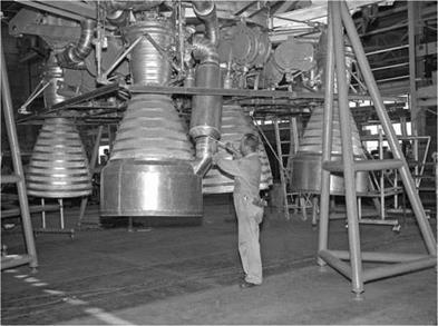


H-1 engines, which were used in a cluster of eight to power the first stage of both the Saturn I and the Saturn IB. (Photo courtesy of NASA)
passed its preliminary flight-rating tests, leading to the first flight test on October 27, 1961.47
Meanwhile, Rocketdyne had begun uprating the H-1 to 188,000 pounds of thrust, apparently by adjusting the injectors and increasing the fuel and oxidizer flow rates. Although the uprated engine was ready for its preliminary flight-rating tests on September 28, 1962, its uprating created problems with combustion instability that engineers had not solved by that time but did fix without detriment to the schedule. The first launch of a Saturn I with the 188,000-pound engine took place successfully on January 29, 1964.48
Development had not been unproblematic. Testing for combustion instability (induced by setting off small bombs in the combustion chamber beginning in 1963) showed that the injectors inherited from the Thor and Atlas could not recover and restore stable combustion once an instability occurred. So Rocketdyne engineers rearranged the injector orifices and added baffles to the injector face. These modifications solved the problem. Cracks in liquid-oxygen domes and splits in regenerative-cooling tubes also required redesign. Embrittlement by sulfur from the RP-1 in the hotter environment of the 188,000-pound engine required a change of materials in the tubular walls of the combustion chamber from nickel alloy to stainless steel. There were other problems, but the Saturn personnel resolved them in the course of the launches of Saturn I and IB from late 1961 to early 1968.49
Because the H-1s would be clustered in two groups of four each for the Saturn I first stage, there were two types of engines. H-1Cs used for the four inboard engines were incapable of gimballing to steer the first stage. The four outboard H-1D engines did the gim – 132 balling. Both versions used bell-shaped nozzles, but the outboard Chapter 3 H-1Ds used a collector or aspirator to channel the turbopump exhaust gases, which were rich in unburned RP-1 fuel, and deposit them in the exhaust plume from the engines to prevent the still-combustible materials from collecting in the first stage’s boat tail.50
The first successful launch of Saturn I did not mean that developers had solved all problems with the H-1 powerplant. On May 28, 1964, Saturn I flight SA-6 unexpectedly confirmed that the first stage of the launch vehicle could perform its function with an engine out, a capability already demonstrated intentionally on flight SA-4 exactly 14 months earlier. An H-1 engine on SA-6 ceased to function 117.3 seconds into the 149-second stage-one burn. Telemetry showed that the turbopump had ceased to supply propellants. Analysis of the data suggested that the problem was stripped gears in the turbopump gearbox. Previous ground testing had revealed to
 |
 |
Rocketdyne and Marshall technicians that there was need for redesign of the gear’s teeth to increase their width. Already programmed to fly on SA-7, the redesigned gearbox did not delay flight testing, and there were no further problems with H-1 engines in flight.51
 None of the sources for this history explain exactly how Rocketdyne increased the thrust of each of the eight H-1 engines from 188,000 to 200,000 pounds for the first five Saturn IBs (SA-201 through SA-205) and then to 205,000 pounds for the remaining vehicles. It would appear, as with the uprated Saturn I engines, that the key lay in the flow rates of the propellants into the combustion chambers, resulting in increased chamber pressure. After increasing with the shift from the 165,000- to the 188,000-pound H-1s, these flow rates increased again for the 200,000-pound and once more for the 205,000-pound H-1s.52
LAUNCH VEHICLE ENGINES
H-l ON SATURN IB FIRST STAGE
F-l ON SATURN V FIRST STAGE
J-2 ON SATURN IB
SECOND STAGE
J-2 ON SATURN V SECOND STAGE
![]() * ALSO SATURN V THIRD STAGE
* ALSO SATURN V THIRD STAGE
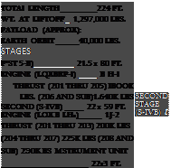
FIG. 3.10 Diagram of the engines used on the Saturn IB and Saturn V. The Saturn IB used eight H-1s on its first stage and a single J-2 on its second stage; the Saturn V relied on five F-1 engines for thrust in its first stage, with five J-2s in the second and one J-2 in the third stage. (Photo courtesy of NASA)
For the Saturn V that launched the astronauts and their spacecraft into their trajectory toward the Moon for the six Apollo Moon landings, the first-stage engines had to provide much more thrust than the eight clustered H-1s could supply. Development of the larger F-1 engine by Rocketdyne originated with an air force request in 1955. NASA inherited the reports and other data from the early de – 134 velopment, and when Rocketdyne won the NASA contract to build Chapter 3 the engine in 1959, it was, “in effect, a follow-on" effort. Since this agreement preceded a clear conception of the vehicle into which the F-1 would fit and the precise mission it would perform, designers had to operate in a bit of a cognitive vacuum. They had to make early assumptions, followed by reengineering to fit the engines into the actual first stage of the Saturn V, which itself still lacked a firm configuration in December 1961 when NASA selected Boeing to build the S-IC (the Saturn V first stage). Another factor in the design of the F-1 resulted from a decision “made early in the program. . . [to make] the fullest possible use of components and techniques proven in the Saturn I program."
 In 1955, the goal had been an engine with a million pounds of thrust, and by 1957 Rocketdyne was well along in developing it. That year and the next, the division of NAA had even test-fired
 |
|
|
|
|
|
|
|
 |
|
|
|
![]()
MS’C-M-INO HAM
such an engine, with much of the testing done at Edwards AFB’s rocket site, where full-scale testing continued while Rocketdyne did the basic research, development, and production at its plant in Canoga Park. It conducted tests of components at nearby Santa Su – sana Field Laboratory. At Edwards the future air force Rocket Propulsion Laboratory (so named in 1963) had three test stands (1-A, 1-B, and 2-A) set aside for the huge engine. The 1959 contract with NASA called for 1.5 million pounds of thrust, and by April 6, 1961, Rocketdyne was able to static-fire a prototype engine at Edwards whose thrust peaked at 1.64 million pounds.53
 Burning RP-1 as its fuel with liquid oxygen as the oxidizer, the F-1 did not break new ground in its basic technology. But its huge thrust level required so much scaling up that, as an MSFC publication said, “An enlargement of this magnitude is in itself an innovation." For instance, the very size of the combustion chamber— 40 inches in diameter (20.56 inches for the H-1) with a chamber area almost 4 times that of the H-1 (1,257 to 332 square inches)—required new techniques to braze together the regenerative cooling tubes. Also because of the engine’s size, Rocketdyne adopted a gas-cooled, removable nozzle extension to make the F-1 easier to transport.54
The engine was bell shaped and had an expansion ratio of 16:1 with the nozzle extension attached. Its turbopump consisted of a single, axial-flow turbine mounted directly on the thrust chamber with separate centrifugal pumps for the oxidizer and fuel that were driven at the same speed by the turbine shaft. This eliminated the
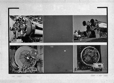
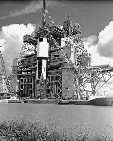
The huge first stage of the Saturn V launch vehicle being hoisted by crane from a barge onto the B-2 test stand at the Mississippi Test Facility (later the Stennis Space Center) on January 1, 1967. Nozzles for the F-1 engines show at the bottom of the stage. (Photo courtesy of NASA)
 136
136
Chapter 3
need for a gearbox, which had been a problematic feature of many earlier engines. A fuel-rich gas generator burning the engine propellants powered the turbine. The initial F-1 had the prescribed 1.5 million pounds of thrust, but starting with vehicle 504, Rock – etdyne uprated the engine to 1.522 million pounds. It did so by increasing the chamber pressure through greater output from the turbine, which in turn required strengthening components (at some expense in engine weight). There were five F-1s clustered in the S-IC stage, four outboard and one in the center. All but the center engine gimballed to provide steering. As with the H-1, there was a hypergolic ignition system.55
Perhaps the most intricate design feature of the F-1 was the injection system. As two Rocketdyne engineers wrote in 1989, the
injector “might well be considered the heart of a rocket engine, since virtually no other single component has such a major impact on overall engine performance." The injector not only inserted the propellants into the combustion chamber but mixed them in a proportion designed to produce optimal thrust and performance. “As is the case with the design of nearly all complex, high technology hardware," the two engineers added, “the design of a liquid rocket injector is not an exact science, although it is becoming more so as analytical tools are continuously improved. This is because the basic physics associated with all of the complex, combustion processes that are affected by the design of the injector are only partly known." A portion of the problem lay with the atomization of the propellants and the distribution of the fine droplets to ensure proper mixing. Even as late as 1989, “the atomization process [wa]s one of the most complex and least understood phenomena, and reliable information [wa]s difficult to obtain." One result of less-than – optimal injector design was combustion instability, whose causes and mechanisms still in 1989 were “at best, only poorly known and understood." Even in 2006, “a clear set of generalized validated design rules for preventing combustion instabilities in new TCs [thrust chambers] ha[d] not yet been identified. Also a good universal mathematical three-dimensional simulation of the complex nonlinear combustion process ha[d] not yet been developed."56
 This was still more the case in the early 1960s, and it caused huge problems for development of the F-1 injector. Designers at Rocket – dyne knew from experience with the H-1 and earlier engines that injector design and combustion instability would be problems. They began with three injector designs, all based essentially on that for the H-1. Water-flow tests provided information on the spacing and shape of orifices in the injector, followed by hot-fire tests in 1960 and early 1961. But as Leonard Bostwick, the F-1 engine manager at Marshall, reported, “None of the F-1 injectors exhibited dynamic stability." Designers tried a variety of flat-faced and baffled injectors without success, leading to the conclusion that it would not be possible simply to scale up the H-1 injector to the size needed for the F-1. Engineers working on the program did borrow from the H-1 effort the use of bombs to initiate combustion instability, saving a lot of testing to await its spontaneous appearance. But on June 28, 1962, during an F-1 hot-engine test in one of the test stands built for the purpose at the rocket site on Edwards AFB, combustion instability caused the engine to melt.57
Marshall appointed Jerry Thomson, chief of the MSFC Liquid Fuel Engines Systems Branch, to chair an ad hoc committee to ana-
lyze the problem. Thomson had earned a degree in mechanical engineering at Auburn University following service in World War II. Turning over the running of his branch to his deputy, he moved to Canoga Park where respected propulsion engineer Paul Castenholz and a mechanical engineer named Dan Klute, who also “had a special talent for the half-science, half-art of combustion chamber design," joined him on the committee from positions as Rocketdyne managers. Although Marshall’s committee was not that large, at Rocketdyne there were some 50 engineers and technicians assigned to a combustion devices team, supplemented by people from universities, NASA, and the air force. Using essentially cut-and-try methods, they initially had little success. The instability showed no consistency and set in “for reasons we never quite understood," as Thomson confessed.58
![]() Using high-speed instrumentation and trying perhaps 40-50 design modifications, eventually the engineers found a combination of baffles, enlarged fuel-injection orifices, and changed impingement angles that worked. By late 1964, even following explosions of the bombs, the combustion chamber regained its stability. The engineers (always wondering if the problem would recur) rated the F-1 injector as flight-ready in January 1965. However, there were other problems with the injector. Testing revealed difficulties with fuel and oxidizer rings containing multiple orifices for the propellants. Steel rings called lands held copper rings through which the propellants flowed. Brazed joints held the copper rings in the lands, and these joints were failing. Engineers gold-plated the lands to create a better bonding surface. Developed and tested only in mid-1965, the new injector rings required retrofitting in engines Rocketdyne had already delivered.59
Using high-speed instrumentation and trying perhaps 40-50 design modifications, eventually the engineers found a combination of baffles, enlarged fuel-injection orifices, and changed impingement angles that worked. By late 1964, even following explosions of the bombs, the combustion chamber regained its stability. The engineers (always wondering if the problem would recur) rated the F-1 injector as flight-ready in January 1965. However, there were other problems with the injector. Testing revealed difficulties with fuel and oxidizer rings containing multiple orifices for the propellants. Steel rings called lands held copper rings through which the propellants flowed. Brazed joints held the copper rings in the lands, and these joints were failing. Engineers gold-plated the lands to create a better bonding surface. Developed and tested only in mid-1965, the new injector rings required retrofitting in engines Rocketdyne had already delivered.59
Overall, from October 1962 to September 1966, there were 1,332 full-scale tests with 108 injectors during the preliminary, the flightrating, and flight-qualification testing of the F-1 to qualify the engine for use. According to one expert, this was “probably the most intensive (and expensive) program ever devoted primarily to solving a problem of combustion instabilities."60
The resultant injector contained 6,300 holes—3,700 for RP-1 and 2,600 for liquid oxygen. Radial and circumferential baffles divided the flat-faced portion of the injector face into 13 compartments, with the holes or orifices arranged so that most of them were in groups of five. Two of the five injected the RP-1 so that the two streams impinged to produce atomization, while the other three inserted liquid oxygen, which formed a fan-shaped spray that mixed with the RP-1 to combust evenly and smoothly. Driven by the
|
52,900-horsepower turbine, the propellant pumps delivered 15,471 gallons of RP-1 and 24,811 gallons of liquid oxygen per minute to the combustion chamber via the injector.61
 Despite all the effort that went into the injector design, the turbopump required even more design effort and time. Engineers experienced 11 failures of the system during development. Two of these involved the liquid-oxygen pump’s impeller, which required use of stronger components. The other 9 failures involved explosions. Causes varied. The high acceleration of the shaft on the turbopump constituted one problem. Others included friction between moving parts and metal fatigue. All 11 failures necessitated redesign or change in procedures. For instance, Rocketdyne made the turbine manifold out of a nickel-based alloy manufactured by GE, Rene 41, which had only recently joined the materials used for rocket engines. Unfamiliarity with its welding techniques led to cracking near the welds. It required time-consuming research and training to teach welders proper procedures for using the alloy, which could withstand not only high temperatures but the large temperature differential resulting from burning the cryogenic liquid oxygen. The final version of this turbopump provided the speed and high volumes needed for a 1.5-million-pound-thrust engine and did so with minimal parts and high ultimate reliability.62
Once designed and delivered, the F-1 engines required further testing at Marshall and NASA’s Mississippi Test Facility. At the latter, contractors had built an S-IC stand after 1961 on the mud of a swamp along the Pearl River near the Louisiana border and the Gulf of Mexico. Mosquito ridden and snake infested, this area served as home to wild pigs, alligators, and panthers. Construction workers faced 110 bites a minute from salt marsh mosquitoes, against which nets, gloves, repellent, and long-sleeved shirts afforded little protection. Spraying special chemicals from two C-123 aircraft did reduce the number of bites to 10 per minute, but working conditions remained challenging. Nevertheless, the stand was ready for use in March 1967, more than a year after the first static test at Marshall. But thereafter, the 410-foot S-IC stand, the tallest structure in Mississippi, became the focus of testing for the first-stage engines.63
Despite static testing, the real proof of successful design came only in actual flight. For AS-501, the first Saturn V vehicle, the flight on November 9, 1967, largely succeeded. The giant launch vehicle lifted the instrument unit, command and service modules, and a boilerplate lunar module to a peak altitude of 11,240 miles. The third stage then separated and the service module’s propulsion system accelerated the command module to a speed of 36,537 feet per second (about 24,628 miles per hour), comparable to lunar reentry speed. It landed in the Pacific Ocean 9 miles from its aiming point, where the USS Bennington recovered it. The first-stage engines did experience longitudinal oscillations (known as the pogo effect), but these were comparatively minor.64
Euphoria from this success dissipated, however, on April 4, 1968, when AS-502 (Apollo 6) launched. As with AS-501, this vehicle did 140 not carry astronauts onboard, but it was considered “an all-important Chapter 3 dress rehearsal for the first manned flight" planned for AS-503. The initial launch went well, but toward the end of the first-stage burn the pogo effect became much more severe than on AS-501, reaching five cycles per second, which exceeded the spacecraft’s design specifications. Despite the oscillations, the vehicle continued its upward course. Stage-two separation occurred, and all five of the engines ignited. Two of them subsequently shut down, but the instrument unit compensated with longer-than-planned burns for the remaining three engines and the third-stage propulsion unit, only to have the latter fail to restart in orbit, constituting a technical failure of the mission, although some sources count it a success.65
As Apollo Program Director Samuel Phillips told the Senate Aeronautical and Space Sciences Committee on April 22, 1968, 18 days
after the flight, pogo was not a new phenomenon, having occurred in the Titan II and come “into general attention in the early days of the Gemini program." Aware of pogo, von Braun’s engineers had tested and analyzed the Saturn V before the AS-501 flight and found “an acceptable margin of stability to indicate" it would not develop. The AS-501 flight “tended to confirm these analyses." Each of the five F-1 engines had “small pulsations," but each engine experienced them “at slightly different points in time." Thus, they did not create a problem. But on AS-502, the five 1.5-million-pound engines “came into a phase relationship" so that “the engine pulsation was additive."66
All engines developed a simultaneous vibration of 5.5 hertz (cycles per second). The entire vehicle itself developed a bending frequency that increased (as it consumed propellants) to 5.25 hertz about 125 seconds into the flight. The engine vibrations traveled longitudinally up the vehicle structure with their peak occurring at the top where the spacecraft was (and the astronauts would be on a flight carrying them). Alone, the vibrations would not have been a problem, but they coupled with the vehicle’s bending frequency, which moved in a lateral direction. When they intersected (with both at about the same frequency), their effects combined and multiplied. In the draft of an article he wrote for the New York Times, Phillips characterized the “complicated coupling" as “analogous to the annoying feedback squeal you encounter when the microphone and loud speaker of a public address system. . . coupled." This coupling was significant enough that it might interfere with astronauts’ performance of their duties.67
 NASA formed a pogo task force including people from Marshall, other NASA organizations, contractors, and universities. The task force recommended detuning the five engines, changing the frequencies of at least two so that they would no longer produce vibrations at the same time. Engineers did this by inserting liquid helium into a cavity formed in a liquid-oxygen prevalve with a casting that bulged out and encased an oxidizer feed pipe. The bulging portion was only half filled with the liquid oxygen during engine operation. The helium absorbed pressure surges in oxidizer flow and reduced the frequency of the oscillations to 2 hertz, lower than the frequency of the structural oscillations. Engineers eventually applied the solution to all four outboard engines. Technical people contributing to this solution came from Marshall, Boeing, Martin, TRW, Aerospace Corporation, and North American’s Rocketdyne Division.68 This incidence of pogo showed how difficult it was for
FIG. 3.14
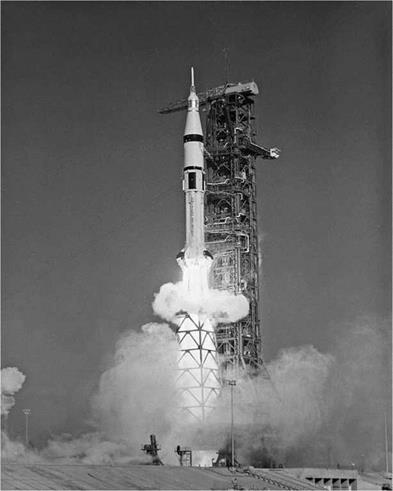
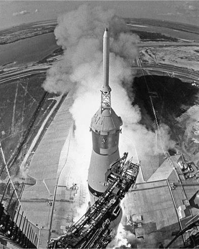 Launch of the giant Saturn V on the Apollo 11 mission (July 16, 1969) that carried Neil Armstrong, Edwin Aldrin, and Michael Collins on a trajectory to lunar orbit from which Armstrong and Aldrin descended to walk on the Moon’s surface. (Photo courtesy of NASA)
142
Chapter 3
rocket designers to predict when and how such a phenomenon might occur, even while aware of and actively testing for it. The episode also illustrated the cooperation of large numbers of people from a variety of organizations needed to solve such problems.
The redesign worked. On the next Saturn V mission, Apollo 8 (AS-503, December 21, 1968), the five F-1s performed their mission without pogo (or other) problems. On Christmas Eve the three astronauts aboard the spacecraft went into lunar orbit. They completed 10 circuits around the Moon, followed by a burn on Christmas Day to return to Earth, splashing into the Pacific on December 27. For the first time, humans had escaped the confines of Earth’s immediate environs and returned from orbiting the Moon. There were no further significant problems with the F-1s on Apollo missions.69
The development of the huge engines had been difficult and unpredictable but ultimately successful.


