Blue Streak – the ‘Underground Launcher’
There was one feature in which Blue Streak was ahead of its time, and this feature, by a process of tortuous logic, was to provide the means by which its cancellation was achieved.
One of the defining images of the Cold War was that of the missile silo: the sight of a missile erupting from a hole in the ground conjured up images of mushroom clouds, radioactive fall-out, megadeaths. One of the less known facts about missile silos is that much of the initial research on launching missiles from underground was carried out near a small village in Buckinghamshire – Westcott.
The first American missiles to be deployed – Thor, Atlas, Jupiter – were all deployed on surface sites, with the only protection for the missile being protection from the elements – wind and rain. These missiles were also very large and very fragile. A sniper a mile away could put a bullet through the tanks and disable the missile permanently. They would be damaged beyond use by the blast from an atomic explosive even though it might have been miles away. In the jargon of the day, they were hopelessly vulnerable to a pre-emptive strike. Later versions of the Atlas missiles were kept in hardened shelters – hardened in this context meaning strengthened against attack – although they still had to be removed from the shelters to be erected, fuelled and fired.
The slightly later Titan I missile was housed in a ‘lift and fire’ silo: the missile was prepared for firing in an underground tube, then lifted to the surface for the moment of firing. This reduced the window of vulnerability to a few minutes, but the vulnerability still existed. The only way to make sure the missile could not be destroyed before launching would be the ‘fire in the hole’ method.
The Minuteman solid fuel missiles that America was in the process of deploying were far more robust than the relatively fragile liquid fuelled rockets. They also had a much greater initial acceleration, meaning they would clear the silo quicker, and so providing a hole in the ground for them was relatively straightforward. Blue Streak, on the other hand, would take several seconds to clear the silo, and there were two major problems to be investigated. The first
was whether the acoustic energy produced from the rocket motors would be sufficient to damage the thin tank walls, the second was the problem of gas flow. How could the exhaust gases (and Blue Streak burned nearly half a ton of fuel a second) be deflected away from the rocket? And what of the gas flow within the tube? Would the missile be pulled towards the wall of the tube?
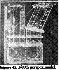
 The problem of vulnerability to preemptive attack had been recognised from the outset, and reference was made in the original requirement to ‘underground launch sites’ without being specific about detail. Initial ideas were very vague, until a proper research programme was started at RPE Westcott. Initial ideas centred around some sort of ‘U’ tube arrangement, with the missile in one arm of the U. To study the dynamics of the gas flow, a 1/60th scale model of the rocket was used, together with jets of high pressure nitrogen gas to represent the rocket exhaust (it is not surprising that the men who worked on this part of the project lost most of their hearing). Perspex models of various configurations were made, with small woollen tufts to show the air flow.1
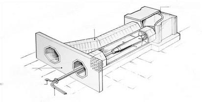
The next step was considerably more expensive. A 1/6th scale model U tube was to be built, complete with an acoustic lining, real rocket motors placed inside, and fired. Microphones would measure sound levels. Rather than excavate
DEFLECTOR BOX
EXHAUST DUCT
SR1CK WALL
SIMULATING
GROUND PLANE.
INSTRUMENTATION CABLES
PROPELLANT SUPPLY PIPES
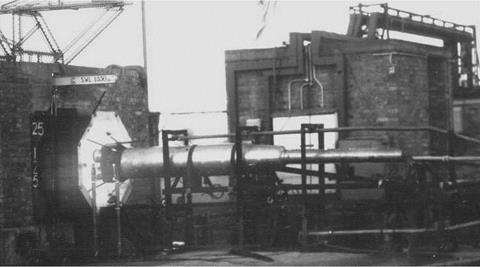
Figure 46. 1/6th scale model of the proposed underground launcher.
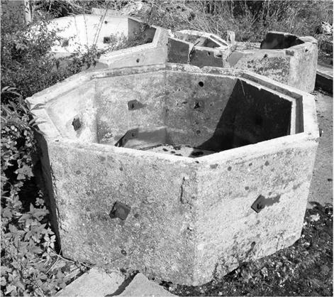
a deep hole, the U tube was built horizontally, on the ground, with a brick wall to simulate the ground plane, as shown in the drawing above. Octagonal concrete sections were built and fitted together, some of which can be seen at Westcott today, although, slightly surprisingly, there is no trace of the model silo itself.
The 1/6th scale missile could then be moved up and down and its Gamma motors fired. Various other effects could be investigated at the same time – for example, the effect of the rocket efflux on the concrete at the bend of the U tube. Low temperature concrete was preferred since it merely tended to melt; high temperature concrete fragmented, and the fragments were swept along the tube, gathering more as they moved along. Reading between the lines, some of the test runs could be somewhat alarming, as this excerpt from a report shows:
|
Figure 47. Remains of the model silo at Westcott as seen in 2010. |
As was expected, the erosion caused directly by the impingement of the jets was small, but small particles removed from the surface were accelerated by the gas stream, and scoured the curved deflector plate downstream of the point of impingement. The effect was cumulative and persisted in the region of high gas speeds and where the deflector was concave towards the jets… Pieces weighing two ounces or more were picked up about 50 yards from the launcher exit.2
But these were not the only problems. What was the effect of a one megaton explosion half a mile away? What effect would the shock wave have on the launcher and the missile, not to mention the personnel inside? The effect of ‘radio flash’ (now known as ElectroMagnetic Pulse or EMP) was unknown, as were the effects of neutron irradiation. Furthermore, the launcher had to accommodate the launch crew for a period of up to 24 hours after hostilities began. They would need living quarters inside the launcher itself.
|
Figure 48. The Gamma motors being fired within the U tube assembly. |
There were turf wars from the outset. The Ministry of Works, part of the Ministry of Supply, would normally deal with constructional matters such as these, but the Air Staff wanted to handle it themselves. Aggrieved, the Permanent Secretary at the Ministry of Works appealed to the Treasury to adjudicate. Emolliently, the Treasury wrote back to say that yes, the Ministry of Works had a very good case, but they had decided to leave it to the Air Ministry since it was they who would have to use the end product. So who would the Air Staff appoint to build the launchers? De Havilland were not popular with the Ministry of
Supply, who found them difficult to deal with. In addition, de Havilland was in bad odour as a consequence of their over-spending (the Treasury at one time was considering sending in the accountants Cooper Brothers, predecessors to today’s management consultants).
|
Figure 49. Another view of the model silo can be seen here, showing how the brick wall was used to represent the ground plane. (Chalked on the wall above the model missile are the words of a song from the then hit musical My Fair Lady: ‘Wiv a Little Bit of Blooming Luck’.) |
A minute in October 1957 said of de Havilland: ‘It should be clear that design of underground sites is in no way the responsibility of this firm, which is already showing itself incapable of carrying the load that has been put on it.’3 On the other hand, there were not many alternatives, and, in the end, the firm was given the job in lieu of anyone else. The evolution of the design can be seen in the various documents still in the National Archives, but the final version was given an airing in a presentation at de Havilland’s offices in Charterhouse Square, London4.
|
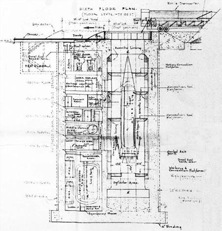
Figure 50. Architect’s drawing of the ‘underground launcher’. |
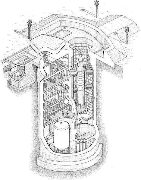
The full specification can be seen in Appendix A, but Figure 50 makes the layout fairly clear. The final design is indeed impressive, as the architect’s drawing shows (Figure 51). The figures of the men inside the launcher give some feeling for the scale of the launcher.
Starting at ground level, the emplacement is surrounded by a built-up bank, and the access road can be seen top right. The missile would have been brought on a transporter, then lowered into the missile shaft. The silo is drawn with the lid open, and the launch and efflux ducts can be seen. On the left is the entrance, with its airtight and blast proof doors.
|
Figure 51. The ‘underground launcher’ reconstructed from the architectural drawings. © English Heritage. From National Archives file AIR 2/17377, drawn by Allan Adams. |
The cylinder is divided into two: one half houses the missile and the shafts, the other houses equipment and the living quarters.
The missile itself is held on a platform attached to the walls by springs or hydraulic cylinders, so that the relatively fragile missile would be insulated from the shock of nearby explosions. There are access platforms around the missile; the warhead would almost certainly be stored separately and would have to be fitted before launch. Around the walls of the shaft is an acoustic lining, product of the research at Westcott.
At the bottom of the launcher is the liquid oxygen tank and the kerosene tanks. Fuelling the missile in the confines of the launcher might well have been a rather hazardous procedure! This was one of the advantages of storable propellants.
Note that the whole launcher is surrounded with a % inch mild steel liner – this, in conjunction with the lid, should act as a gigantic Faraday cage. This was to protect the launcher from EMP which might otherwise destroy all the electrical and electronic equipment inside. Looking at the thickness of the walls, building these launchers would have had a considerable impact on Britain’s production of concrete!
A description of the prototype launcher, code named K11, says:
Basically, the emplacement consists of a hollow re-inforced concrete cylinder, 66 feet internal diameter, extending downwards from ground level to a depth of 134 feet and divided internally into two main sections by a vertical concrete wall. One section houses a U-shaped tube, whose arms are separated by a concrete wall and are, respectively, the missile shaft and its efflux duct. The surface apertures of this U-tube are covered by a lid that can move horizontally on guide tracks. The other main section within the cylinder is divided into seven compartments, each with concrete floor and ceiling, for the various storage, operating, technical and domestic functions.
The internal diameter (66 feet) of the concrete cylinder is determined solely by what is to be accommodated. Protection against [a 1 megaton explosion at Vi mile distance] is given by the lid and by the re-inforced concrete roof walls and foundations. The wall thickness will depend on the geological characteristics of the surrounding rock and may well be of the order of 6 feet. The depth of 134 feet is arrived at primarily to give sufficient clearance below the missile (itself 79 feet long) to allow for de-fuelling and re-fuelling the missile into and from the liquid oxygen and kerosene storage tanks located on the 7th floor.
The 400 ton steel lid could be opened in 17 seconds, and high pressure hoses would sweep it clear of debris first. Two firms, John Brown (SEND) [Special Engineering & Nuclear Developments], and Whessoe Ltd of Darlington, were commissioned to produce designs. Whessoe’s report is dated March 1960, so that it is obvious that the design of the lid had not been finalised by the time of the cancellation. This, combined with the problems of finding a site for K11, meant that the schedule must have been slipping seriously. To have produced a fully working prototype by 1963 or 1964 on this basis looks difficult to achieve.
Brown’s lid was 56 ft by 36 ft, weighing 600 tons. Both were hollow, although with strong internal bracing, and in Brown’s case, 5 ft thick. The Whessoe lid used 3 inch thick steel plate top and bottom. The lids were to be capped with 6 inches of concrete. The rails on which the lid was to run were also of steel, in Brown’s case 7 inches square in cross section, and for Whessoe, ‘12 inch overall width by 5% inch rail width’.
John Brown’s submission noted that
the front edge will have an angled profile to act as a plough in the event of it being necessary to clear any rubble which may accumulate on the track. The two 36’ sides will house pairs of four-wheeled bogies, and a continuous rack will run down the outside of these faces, engaging on a pair of pinions.. .5
When considering the electrical drive mechanism, it was noted that the requirement stated:
A cover weighing 600 tons has to be moved from the open to the closed position in 17 seconds and fine positioned to within half an inch within a few seconds of the end of this period. Alternatively, it has to be opened without fine positioning in 17 seconds. The time allowed for lifting the jacks is 5 seconds so that 12 seconds remain for the operation.6
Provision was also made for keeping the lid free from debris, although the ground shock the silo was predicted to receive would be considerable. There are references in a de Havilland paper to ‘Ground shock… in a vertical direction, an instantaneous step velocity of 2*4 ft/sec is induced, which decays at a uniform rate to zero in one second… in a horizontal direction, an instantaneous velocity of % ft/sec is induced which decays at a uniform rate to zero in one second’, whereas Whessoe notes that there are ‘Acceleration forces on Ancillary Equipment equivalent to accelerations of 2g’7. In addition, the rails would be exposed to heat from the fireball. The question this raises is whether the rails buckle under these loads and hence jam the wheels. A silo whose lid cannot be opened would not have been much use!
Other aspects of the design were to cause concern: the various effects created by a nuclear explosion nearby. Whilst the silo might survive the blast, there were concerns as to the effects of EMP and of high energy neutrons. The RAE Lethality Committee set to work to investigate these effects.
One effect, of course, is the thermal radiation or heating. Being underground, the launcher was relatively immune from this, although the lid and the rails would be exposed. This was not thought to be a significant problem. The high temperatures and energetic radiation produced by nuclear explosions also produce large amounts of ionised matter that is present immediately after the explosion. Under the right conditions, intense currents and electromagnetic fields can be produced, generically called EMP (Electromagnetic Pulse), that are felt at long distances. Living organisms are impervious to these effects, but they can temporarily or permanently disable electrical and electronic equipment. Ionised gases can also block short wavelength radio and radar signals (fireball blackout) for extended periods.
The occurrence of EMP is strongly dependent on the altitude of burst. It can be significant for surface or low altitude bursts (below 4,000 m); it is very significant for high altitude bursts (above 30,000 m); but it is not significant for altitudes between these extremes.
This was the reason for the steel liner to the silo: it would act as a Faraday cage, whereby the strong magnetic and electrical fields pass through the liner without affecting anything inside. For this to be effective, the cage must have no openings through which energy could leak. Studies were carried out on the consequences of such details as pipework into and out of the silo, and what effect they might have.
The main radiation hazard came from high energy neutrons, which would not only affect the warhead but also the crew inside the silo. One of the purposes of the lid was to act as a neutron absorber (the water within the concrete would help).
In addition, the equipment in the silo might be protected against ground shock, but the crew themselves could be seriously injured. There was even a proposal to keep a spare crew suspended in hammocks ready to take over. The missile itself would be suspended on hydraulic cylinders to act as dampers against the ground shock.
The work done at Westcott can be said to have validated the concept of the launcher (it was estimated at the time of cancellation that the Westcott work had cost £1.8 million). It is also of interest that the British design studies preceded any undertaken in the US, and Colonel Leonhardt, deputy commander for Installations, Ballistic Missile Installations, visited the UK to evaluate the design for the underground launcher. Dr Barry Ricketson of RPE travelled to America in 1959, as the minutes of a meeting noted: ‘… Dr Ricketson was at present in the United States giving the Americans the knowledge he had acquired in his studies of the problems of launching ballistic missiles from underground.’8
A similar research programme, which seems closely based on Westcott’s work, was carried out in the US, where again a 1/6th scale model was tested. The Titan II silo design that resulted can be seen to have a family resemblance to the Blue Streak launcher (although similar problems lead to similar solutions). The last Titan silo was not taken out of commission until 1987, which tends to argue against any obsolescence of the UK design.
Within the silo, there would be a crew of three officers and five men per shift, and the crucial point of the OR for the launcher was that:
… the emplacement must be self-contained for an emergency period of four days (covering three days before an attack is expected and one day afterwards).
This is the pivotal issue for the silo concept: early warnings, launch times and the rest were irrelevant. Indeed, although much had been made of the fact it would have been impossible to launch Blue Streak between the time that an incoming attack was detected and the time when it arrived, this misses the point entirely. The UK would never have launched ‘on warning’. There were no facilities for doing so. A man carrying the codes for a nuclear attack follows around the US President throughout his time in office, but in the UK there has never been such provision. There would have been very many times when the Prime Minister would have been inaccessible, such as when he was in his car on the way to Chequers, for example, and authority to launch would not have been delegated to the military.
The point of Blue Streak was to act as a deterrent, so that if the UK were attacked with atomic weapons, it would have the ability to retaliate for a period of up to at least 24 hours after the initial attack, although there is no reason why this period could not be longer. The UK might not then be a functioning society any more apart from this one vital aspect – its ability to strike back at its attacker. That was the point of deterrence. But would the launchers in fact be capable of this? Some thought so, when the effect and accuracy of Russian missiles was being discussed. Thus, in a Ministry of Defence memo in June 1958:
This does not mean that a potential enemy attack with weapons achieving a c. e.p. of Vi mile would invalidate Blue Streak as a weapon. With a c. e.p. of Vi mile, one MT weapon delivered at each site would have a 50% probability of neutralizing a site. [This was an estimate based on the silo design and the known effects of nuclear explosions.] Thus to achieve an acceptable probability of destroying our retaliatory capability, a much higher ratio than one attack per site would be required; for example, more than 3 attacks per site would be required for a 90% probability and, if the reliability of the attacking weapons system is, say, 70% then more than 4 launchings against each target would be required. Alternatively, to give a 90% probability of putting a Blue Streak site out of action with 1MT delivered, a c. e.p. of
V mile would be required and again additional launches would be needed to offset the inevitable less-than-100% reliability. [c. e.p. is circular error probability; the chance of 50% of missiles arriving within this radius.]
A paper prepared in 1959 gives some idea of the projected costs:
The Ministry of Supply estimate that the total R&D cost of a below-ground Blue Streak would be £160-£200M, broken down as follows:
Underground Deployment
100 sites at £2M per site £200M
100 missiles at £0.5M per missile £ 50M
10 years operating costs at £0.125M per missile per year £125M
R&D £160-£200M
Warheads £100M
Total £635-675M
Even with only 60 missiles deployed, which would have been the probable final total, these are impressive sums for 1959. But they were only estimates, based on no hard data, and the history of such projects made it very clear to everyone except the Ministry of Supply that all such estimates were usually wild underestimates. The Treasury, of course, was more cautious: in January 1958 it gave authority to start work on Australian facilities. However, it went on ominously, ‘commitments on the part of the launchers related to “below ground” aspect are to be kept to a bare minimum and no work should begin on the “below ground” part of the launchers themselves.’9
Air Vice Marshall Kyle, Assistant Chief of Air Staff (OR), had to write to the Treasury:
At our meeting on Monday, 21st April [1958], in the Ministry of Defence, the requirement for underground launching for Blue Streak was queried and I confirmed then that this was the firm intention of the Air Council. From the attached note you will see that this has been made plain for well over a year and that the need for underground siting was envisaged in the original O. R. for the missile.10
Similarly, the Ministry of Supply argued that the idea of underground siting had been outlined in the 1958 Defence White Paper. The Treasury dismissed this by saying: ‘… the Treasury would never accept that a unilateral statement in a Defence White Paper committed the Government to any particular policy.’ One does wonder then what the point of a Defence White Paper was. The idea that a Defence White Paper would be published without having been cleared by the Prime Minister is more than a little absurd.
In Australia, a U tube launcher was to be built in the side of a ravine to avoid unnecessary excavations. A similar idea was pursued at Spadeadam, where English Heritage has recently investigated the site:
A letter from the Ministry of Supply to the Treasury shows that plans were well- advanced for the construction of an underground ground launcher at Spadeadam by September 1958. Trial bore holes had been drilled during the summer and permission was sought to begin the construction of a full size silo at a cost of £690,000, plus a 15 per cent agency fee. Owing to the proximity of the bedrock to the surface and the great expense (and time) that would be incurred excavating a hole 150 feet deep, it was planned to dig a 30 feet hole through the overburden down to the bedrock. The base of the silo would be placed in the hole while the remainder of the structure would be above ground. It was also proposed to place the missile silo hole close to the Greymare Hill Missile Test Area so that advantage could be taken of its technical infrastructure.
A contemporary air photograph taken in August 1961 confirms that work had begun on the silo. It shows an excavation with disturbed ground to its north and traces of heavy vehicle tracks leading westwards back towards the southern end of the Greymare Hill complex. Following the cancellation in April 1960, all major civil engineering work was halted, proving that this work had taken place prior to that date. Subsequent to the abandonment of the project, the silo trials area was covered by a dense coniferous plantation, effectively hiding the site from view for over forty years.11
In the UK, a full engineering prototype launcher was to be built, but finding a site for K11 and indeed for the rest of the silos was not easy. In June 1957 a list of 92 possible sites had been prepared, but only by looking at a map for disused Ministry of Defence properties. In a stroke of lateral thinking, more than 40 roadstone quarries were looked at for suitability: after all, there was already a hole there, and roadstone was good and hard. Geologically, the silos had to be sited in hard rock or other fairly rigid material such as chalk. By October 1958, there was talk of Duxford for the site of K11, with alternatives at Odiham, Waterbeach and Stradishall. By January 1959, Castle Camp, Ridgewell, Sudbury, Raydon and Lasham had made their way onto the list12.
Although there was talk of building clusters of six silos at a time, the sites had to be well separated by distance of several miles, so that one site would not be affected by attacks on other sites. But in February 1959, there was a change in policy: ‘the first sites should be in the South of England, North of the Thames’, and twelve disused airfields had been surveyed by March. These were Castle Camps in Cambridgeshire, Ridgewell in Essex, Tibenham and Hardwick in Norfolk, and Eye, Beccles, Sudbury, Metfield, Raydon, Bungay, Halesworth, and Horeham, all in Suffolk.
A problem emerged at Duxford, however: discovery of the water table 40 ft down and the resultant flow of water rendered it unsuitable13. Another site had to be chosen, and Upavon and Netheravon in Wiltshire were then earmarked for the job.
But now the Home Office intervened: they wanted the sites well away from any evacuation areas, and on the East Coast, so that fallout would be carried away by the prevailing winds. Upavon was dropped from the list of sites as a result. The 1959 election then intervened, holding up the progress, and after the election the emphasis changed: now the RAE was sent up to Yorkshire and Durham to look at the likes of Acklington and Eshott as locations for the K11 site. Similarly, the VCAS favoured Ouston or Morpeth.
Bircham Newton in Norfolk was also a strong contender, and the RAF went to investigate its geological suitability, as this memo from Wing Commander Wood indicates:
I had a long talk with the Station Commander Bircham Newton (Group Captain Walford) during my visit yesterday. He was rather upset about some of the unavoidable mess (mostly vehicle tracks) which the Soil Survey Team have made on the airfield as he is trying to have the whole place look spotless for a visit by C. A.S. [Chief of the Air Staff] on 16th October [1959] – I undertook to see that everything was tidied up. The Group Captain also asked for guidance should he be asked about the holes on the airfield which will still be evident.. .14
Once the deliberations of the BND(SG) began to leak out, progress became even slower. A memo from the Ministry of Aviation to the Ministry of Works in January 1960 contains the paragraph:
We are still not in a position to give you instructions to proceed on procurement for K.11 pending the completion of the current Defence review. There has been considerable correspondence at Ministerial level and it has been agreed that until the Defence review has been completed no new major commitments can be entered into on the Blue Streak project. Certainly K.11 is a ‘major new commitment’.
One thing was certain: by the time of cancellation no site had been fixed upon, no excavation had been started, the design was not complete and the chances of K11 being operational by 1964 were looking increasingly remote. [5]
3 TNA: PRO AVIA 92/18. Design of firing sites for ballistic missiles : policy.
4 TNA: PRO DEFE 7/2247. Development of Blue Streak.
5 TNA: PRO AIR 2/11115. Underground launcher: protective cover; design study.
6 Ibid.
7 TNA: PRO AIR 2/11131. Underground launcher: protective cover; design study.
8 TNA: PRO AVIA 92/19. Design of firing sites for ballistic missiles: policy.
9 ![]() TNA: PRO AVIA 92/18. Design of firing sites for ballistic missiles: policy.
TNA: PRO AVIA 92/18. Design of firing sites for ballistic missiles: policy.
DEFE 7/2245. Development of Blue Streak.
1 Cockcroft, W. (2006). ‘The Spadeadam Blue Streak Underground Launcher Facility U1’ Prospero 3 pp. 7-14.
12 TNA: PRO AIR 2 14701. Blue Streak: selection of sites.
13 Ibid.
14 Ibid.


