The Missile Design
The rocket structure, like Ancient Gaul, could be thought of in three parts: the engine bay at the bottom, the main tank structure containing all the fuel in the missile, and the ancillary equipment, guidance and payload at the top. The engine bay, containing two RZ 2 motors, was 9 ft in diameter (so designed for transport by air), but the elegance of the final shape of the missile was rather spoiled by two panniers either side containing nitrogen to pressurise the kerosene tank. The liquid oxygen tank could be pressurised by oxygen gas derived from the liquid via heat exchangers. So in June 1957, de Havilland stated that
the propellant tanks, constructed of 0.019 inch thick stainless steel, remained unaltered. External stringers on the rear (kerosene) tank would permit the weight of the head to be supported without pressuring the rear tank. This would in turn allow the kerosene to be drained from the missile in the event of a failure occurring on the launcher.18
The upper tank had to be kept pressurised at all times to prevent the structure collapsing under its own weight. These 48 stringers also helped to give Blue Streak its distinctive appearance. Inside the fuel tanks were various baffles to prevent the sloshing of fuel, but missiles such as Blue Streak are not much more than gigantic thin-walled tanks.
For Atlas, skin gauges varied throughout the structure, being tailored to meet local stresses. The heaviest skin gauge was forty thousandths of an inch. By comparison, the skin gauge for Blue Streak was nineteen thousandths, but the lower section, the kerosene tank, was re-inforced with stringers. Blue Streak was simpler in being a pure cylinder, whereas the Atlas tanks tapered at the top. The most probable cause of the failure of such a structure in compression is what is known as Euler buckling – the process that occurs when you step onto an empty soft drinks can. But there were other reasons for the reinforcements.
A structure such as Blue Streak or Atlas is also very vulnerable to sideways bending forces, particularly when transmitting large loads vertically. These can originate from sideways gusts of winds, and also from the act of swivelling the rocket motors off centre for control purposes. Indeed, the two motors were to be inclined inwards slightly so that their thrust lines passed through the centre of gravity of the missile. Another problem to which liquid fuel rockets are prone is ‘sloshing’ which occurs when the liquid sloshes from side to side in the tanks as the vehicle rocks. Although it is often said that Blue Streak performed impeccably for ELDO in the 1960s and 1970s, this is not quite true. Sloshing of the fuel towards the very end of the first flight, F1, on 5 June 1964, overcame the control system and caused the missile to tumble uncontrollably.
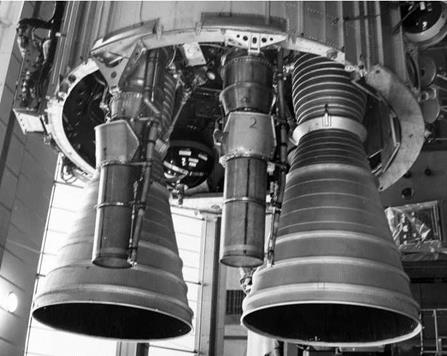
The most important parameter for a ballistic rocket using no aerodynamic lift forces is the engine thrust. Two of the RZ 2 motors (see Figure 39) gave a thrust of 270,000 lb. Given that the smallest practicable initial acceleration is 0.3 g (and there is a good case to make this bigger in a missile) then the lift-off weight is of the order of 200,000 lb. Some of this, perhaps 4,000 lb, is payload. The rest is divided between fuel and structure, so that structure plus fuel amounts to 196,000 lb. Given 10% as structure, as an arbitrary figure, then this gives fuel weight as around 175,000 lb. Given the densities of the fuels, their volumes can be calculated. Given a diameter for the rocket – say 10 ft – then the length of the tanks can be estimated. Using these ‘back of the envelope’ calculations, then the outline of Blue Streak is quite easily arrived at. For comparison, the F1 vehicle with a dummy load of a ton, had a lift off mass of 205,000 lb, 190,000 lb of which was fuel. Detailed design is, of course, another matter.
Some of the design details were more obvious than others – for example, the tanks needed pressurising. For the oxygen tank this was simple enough: a small amount of the liquid can be vapourised in a heat exchanger and piped up to the tank. Pressurising the kerosene tank with oxygen gas would not have been a good idea: instead, nitrogen gas was used, being stored in spherical bottles in panniers either side of the engine bay.
Whilst the tank section was to be built and tested at de Havilland’s site at Hatfield, testing the rocket motors was another matter. A purpose-built site would be needed for engine development and also for static firing of the complete vehicle. Not only would this be extremely noisy, it was potentially quite hazardous given the amount of combustible fuel contained within Blue Streak’s tanks. The site chosen was Spadeadam on the moors near Carlisle.
|
Figure 39. The Rolls Royce RZ 2 rocket motors that powered Blue Streak. |
The Treasury was of course concerned with the cost: an estimate of £10.2 million for the construction of the Spadeadam site in April 1956 had become £12.3 million by October (and the final cost would be much higher). There is an interesting comment in a slightly later memo:
If a decision were taken to stop work on the MRBM… there would be a saving of some £70m. or more over the next ten years.19
If only the total cost had come to a mere £70 million! The decision to go ahead with Blue Streak was not yet firm at this time, and a further memo noted:
… it is probable that in the Policy Review a choice may have to be made between the supersonic bomber and the MRBM as research and development projects. The cost of R. and D. for the supersonic bomber would be about £70 million over the next 10 years – roughly the same figures as those for the MRBM, but the costs of producing and maintaining an appropriate number of supersonic bombers . would probably be higher than the costs of an appropriate number of MRBMs.20
Spadeadam was split into five areas: the Administration area; the liquid oxygen factory, which was owned and run by the British Oxygen Company; the Component Test Area situated at Rushy Knowe; the Engine Test Area at Prior Lancy; and the Rocket Test Area situated at Greymare Hill.
The site is described in a Ministry of Aviation paper of November 1961 (the English is slightly eccentric at times):
The Spadeadam Rocket Establishment was built by the Ministry of Works on behalf of the Ministry of Aviation for the purpose of developing and the static testing of the British Ballistic Missile ‘Blue Streak’.
The Establishment is situated on the Cumberland Fells about twenty miles North-east of Carlisle and covers an area of approximately 8,000 acres. It comprises five main areas, three of which are test areas for the static testing of the complete missile, propulsion units and of the rocket engine component parts respectively.
As a safety measure these areas are separated by distances of up to one and three-quarter miles. This dispersion has required the construction of six miles of road connecting the ‘Areas’ on the Establishment.
MISSILE TEST AREA
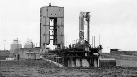
This Test Area comprises two missile stands each with a traversing servicing tower on which the missiles are statically tested including the firing of the propulsion units.
By means of the gantry incorporated in the servicing tower, the missile is erected into the vertical firing position on the concrete emplacement situated at the end of a 300-ft concrete causeway.
Built into the emplacement is a steel flame deflector weighing nearly seventy tons for deflecting to the horizontal plane the jets of the rocket motors.
The large quantity of water required to maintain the temperature of the flame deflectors at a safe temperature level is pumped to the test stands via 36" diameter pipelines supplied from a one-million gallon reservoir situated adjacent to the Missile Test Area.
The necessary liquid propellants and high pressure nitrogen gas used for pressurising are stored in this area.
The Missile tests are instrumentated and controlled remotely from a central blockhouse situated approximately 1000-ft. from the test stands (both of which stands will be evacuated when firing is taking place on either stand) built of reinforced concrete. The tests may be observed from the Control Block-house by means of periscopes and closed-circuit television. In addition to the recording of test data on magnetic tape, film records of the tests are made by cine-cameras situated at strategic points around the test stand.
The main Instrumentation System comprises 19 Control Consoles, 4 Checkout Consoles, (46 Chart-type Recorders) with a capacity of 285 channels and three types of magnetic tape recorders with a total of 32 Information Channels. The Control Centre and each test Stand are connected by over 3,500 wires.
ENGINE TEST AREA
This area, in which the individual propulsion units are test fired, consists of three engine test stands… spaced 250-ft apart. A fourth test stand is partially complete.
Each stand consists of a massive concrete and steel structure in which the liquid propellant rocket engines are mounted to fire vertically downwards into a water cooled flame deflector which deflects the flame into the horizontal plane. The propellants used are Kerosine for the fuel and liquid oxygen for the oxidant. The early engine produced and evaluated by R-R Ltd. developed 135,000-lb thrust.
|
Figure 40. The picture above shows a flight model Blue Streak (note the painted spiral) on a test stand at Spadeadam. The vehicle would be assembled, filled with fuel, and static fired before being shipped out to Woomera in Australia for launch. |
The quantity of water used for flame deflector cooling, storage facilities and transfer systems are similar to those provided in the Missile Test Area.
At a distance of 600-ft from the nearest Engine Test Stand is the Control Blockhouse constructed of 2-ft thick reinforced concrete. This building is equipped with 130 chart-type recording instruments, four 24-channel oscillographs and, when fully equipped, eight control consoles for the remote control of the test equipment and the rocket engine during test. A large number of chart recording instruments are needed to obtain the maximum amount of technical data during the short duration of the test.
An underground concrete duct, 7-ft square and 1,100-ft in length, inter-connects the test stands with the control room for the routing of approximately 8,000 instrumentation and control cables.
The test firings are also recorded by cine-cameras from various locations around the test stands, the cameras being controlled remotely from the control room. These filmed records in addition to the other test records are processed and analysed in the Establishment.


