Solid Fuel Motors
In principle, solid fuel motors are very simple. A tube is filled with the fuel/oxidant mixture, which is then ignited – but as always, there is rather more to it than that. Early motors used simple cordite, a mixture of nitroglycerine and gun cotton, and were end burning – that is, the cordite at the end of the tube is ignited, and the cordite burns upwards towards the other end. Cordite was
 replaced by propellants based on ammonium perchlorate (NH4ClO4) and ammonium picrate (C6H2(NO2)3O. NH4) with small amounts of other material added.
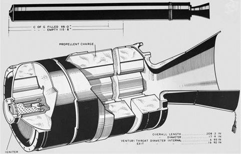
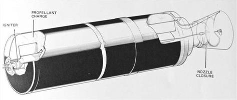
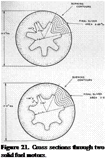
A British innovation was that of centre burning. An empty cylinder runs the length of the tube. The igniter is at the top, and when initiated, the fuel burns from the centre out to the edges. One obvious problem is that the surface area increases as the burning spreads out, and one way to overcome this is to have a star-shaped cut out (see Figure 21).
From the military point of view, solid fuel missiles are vastly preferable to liquid fuelled ones. The solid fuel tube has to be very strong to withstand the high pressures and temperatures inside, thus making it
very robust when it comes to handling. Liquid fuelled missiles, however, have very thin tank walls, and in any accident there is the potential to spill a good deal of rather nasty liquid. With solid fuel motors, it is a question of point and fire; liquid fuelled missiles need a good deal of careful setting up.
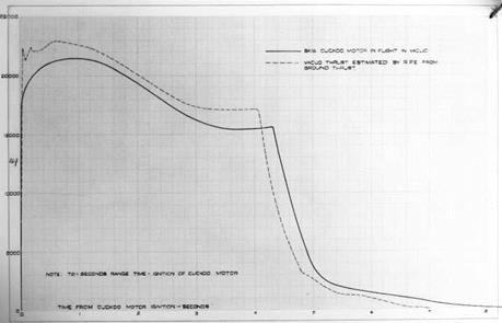
Solid fuel motors have other advantages: by varying the geometry or the combustion mixture, motors can be made that give very large thrusts for very short periods of time, or smaller thrusts for a longer period. The Gosling boosters for the Bloodhound missile accelerated the vehicle to over Mach 2 in three seconds. The thrust is not uniform, as the graph below shows11. In particular, there tends to be a long tail off as the last slivers burn away (see Figure 23). For these reasons, the thrust and burning time given in reports are only approximations.
Solid fuel motors have two disadvantages in a satellite launcher: they tend not be very energetic (have a low S. I.) and have a poor mass ratio (mass full/mass empty). S. I. is related to the exhaust velocity of the gas (in modern units, they are the same), and final velocity of a rocket stage is given by:
Vf = Ve x ln(mass ratio)
|
Figure 22. Rook solid fuel motor. |
Thus the first Black Knight rocket, BK01, had an all up weight at launch of 13,072 lb, and 1,424 lb when empty. Hence its mass ratio was (13,072lb/1,424lb) = 9.18. With an S. I. of around 220, its final velocity in the absence of any other forces would be (220 x 9.8) x ln(9.18) = 4,800 m/s. Performing the same calculation on the Cuckoo II motor, used as the second stage on later Black Knight vehicles, gives 3,750 m/s – quite a significant difference.
There are two obvious ways of improving performance: increasing the S. I. of the fuel, and making the case lighter. Hence later solid fuel motors became more efficient. The solid fuel boosters either side of the Shuttle have an S. I. of 242 at sea level (268 in vacuum). There is also another way to improve performance, which is simply to build them bigger. The mass ratio improves with size since the amount of material for the case is proportional to the radius of the tube, whereas the amount of fuel inside is proportional to the square of the radius.
Most British solid fuel motors were relatively small. The largest was the Stonechat, with a diameter of 36 inches. The Stonechat formed the basis of the Falstaff vehicle, which was used to test components of the Chevaline system. (Chevaline was a Polaris upgrade programme whereby one of the three re-entry vehicles and its warhead was removed to make way for an elaborate system of decoys.) Even so, its total impulse was only 1,700,000 lb. s as against Black Knight’s 2,300,000 lb. s.
|
Figure 23. Thrust/time curve for a Cuckoo motor, showing the tailing off of the thrust near the end. |
It is interesting to compare Stonechat to the Algol 1 motor (first flown in 1960), which was used as the first stage of the original Polaris missile and also as the first stage of the Scout satellite launcher.
|
Figure 24. The Stonechat 36-inch solid fuel motor. |
|
Stonechat: |
Algol 1 |
|
|
Weight: |
10,300 lb |
23,600 lb |
|
Diameter: |
36 inches |
40 inches |
|
Thrust: |
32,000 lbf |
106,000 lbf |
|
Burn time: |
53 seconds |
40 seconds |
|
Sea level S. I.: |
212 |
214 |
In terms of S. I., the two look equivalent, and the mass ratios compare quite favourably, being (23,600/4,100) = 5.8 for Algol and (10,300/1,800) = 5.7 for Stonechat. The later A3 Polaris missile had a first stage with a much better mass ratio: (24,400/2,790) = 8.7. The weight saving was achieved by using a fibreglass casing.
Several 17-inch motors derived from a motor called Smoky Joe, so named from the plume it produced when burning. These include the Albatross, Cuckoo, Goldfinch, Raven and Rook. The Raven and Rook motors were employed in a variety of different roles in the 1950s and 1960s.
The motor tube of the Rook and the Raven consisted of two wrapped and welded cylinders 90 inches long which were butt welded together. The tube was made of steel of thickness 12 SWG (0.104 inches or 2.64 mm). Head ends were welded to the tube: the top end had a threaded opening for allowing the charge former to be centralised during propellant pressing and allowing excess propellant to ‘bleed’ off. Later, the igniter would be fitted in the opening.
These two motors formed the backbone of the various solid fuel vehicles used for a variety of research purposes, with several hundred motors being fired. The Raven formed the basis of the Skylark vehicle.
Below is a table listing a few of the motors developed at RPE. This is taken from a manual of solid fuel motors which listed data for a total of 73 different types of motor12.
|
Motor |
Thrust (lb) |
Burn Time (seconds) |
S. I. |
Weight (lb) |
Length (inches) |
Diameter (inches) |
|
Cuckoo I |
18,200 |
4.1 |
204 |
524 |
51.7 |
17.2 |
|
Cuckoo II |
8,200 |
10 |
213 |
500 |
51.8 |
17.2 |
|
Raven VI |
15,000 |
30 |
191 |
2,540 |
206 |
17.2 |
|
Smoky Joe |
2,900 |
39 |
171 |
925 |
123 |
17.2 |
|
Stonechat |
32,000 |
53 |
212 |
10,300 |
216 |
36.3 |
|
Waxwing * in vacuum |
3,500 |
55 |
*282 |
761 |
49.7 |
28 |
These data are taken from an index of solid fuel motors developed at RPE Westcott in the mid-1960s. The table shows only a small selection – 73 motors were listed in all. These rockets were used for a variety of different purposes:
 Extra boost for first stage of Skylark.
Black Knight re-entry tests.
Skylark.
Black Arrow – stage separation and to settle propellants in tanks. Red Shoes, which became the Thunderbird SAM.
Falstaff vehicle for testing of Chevaline components.
Third stage of Black Arrow.
The most famous solid fuel rocket produced in Britain was Skylark, which had a remarkably successful career. First launched in 1957, from Woomera, its final launch took place from Esrange, Sweden, on 2 May 2005. In all, there have been 441 launches, from sites in Europe, Australia, and South America.
The design first dates to 1955, when initial work was carried out by the RAE and the RPE. The first vehicles were ready less than two years later, and sent for testing to Woomera during the International Geophysical Year.
During the 1960s Skylark evolved into an excellent platform for space astronomy, with its ability to point at the Sun, Moon, or a star. It was used to obtain the first good quality X-ray images of the solar corona. Within the UK national programme, the frequency of Skylark launches peaked at 20 in 1965 (from Woomera), with 198 flights between 1957 and 1978.
|
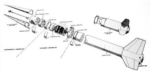
Figure 25. The Skylark sounding rocket. |
Skylark began as a simple one stage vehicle, with three fins and a relatively long burn time of 30 seconds, using the Raven motor. This was to keep the accelerations within reasonable values. A series of different Raven motors were produced, each with a different filling as requirements changed. As a consequence of the low acceleration, a tower was needed to guide the rocket for the first few seconds. This was simple in construction and used components from Bailey bridges!
An extra boost stage was added to improve performance. Initially, this was the Cuckoo motor (so named, apparently, because its function was to kick the Raven out of its nest). Later versions used the Goldfinch motor in place of the Cuckoo.
The following description of how Skylark was used by the space science community was written by Professor Mike Cruise13, who has had a long and distinguished career in space science.
Many of the senior space scientists around the world were trained in space instrument design, data analysis and space project management on projects using the Skylark sounding rocket as the space platform. In the nineteen sixties and seventies over two hundred Skylarks were launched from sites in Norway, Sardinia, Australia and South America offering five minutes of observing time above 100 km and substantial payload carrying capacity. Many of the Skylark flights delivered data which ended up in Doctoral Theses, launching the careers of the students involved. A PhD gained by this route involved science, engineering, travel and exposure to many different professional cultures…
The scientific instrument was constructed on a circular bulkhead of magnesium alloy which was previously delivered from BAE as part of the Skylark ‘Meccano kit’ … The design of the Skylark provided great flexibility for the experimenter. Holes could be cut in the cylindrical bays or in the circular bulkheads provided the design was approved by BAE at Filton. The strength of the vehicle was in the magnesium alloy cylindrical skin. Generally four or five cylindrical bays would be mounted on top of one another containing the parachute, batteries, the control and telemetry systems and then the attitude control system if one were employed. Usually the experiment bay was mounted at the top under a conical nose cone which split longitudinally in two sections after reaching altitude.
A few hours prior to launch, the stack of Skylark bays with the nosecone at the top and the parachute bay at the bottom was mounted on a small trolley and taken by road to the Skylark launcher. The vehicle was rail launched – that is, there were three parallel rails mounted vertically in the launch tower and metal shoes were fitted at various positions along the length of the vehicle to engage with these rails. The fins extended outside of the rails, in the azimuthal spaces between them… The launcher tower was about 50 metres tall and the whole launching assembly could be tilted to angles of about 15 degrees from the vertical to adjust the trajectory for winds.
It was necessary to make calculations of the ballistic winds at various heights to predict the trajectory as the vehicle was only powered for 35 seconds of the ascent phase and had no guidance system.
Balloons were launched and tracked by radar for several hours beforehand to provide this data on the winds up to 10 or 15 kilometres altitude. In addition, there were various instrumentation checks and the firing of sighter rockets to check that all the radars and kine-theodolites were functioning correctly before a firing took place.
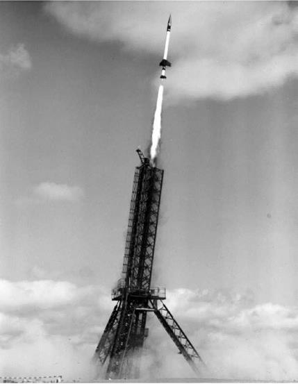 Figure 26. A Skylark launch from Woomera.
Normally the experimenters watched the launch proceedings from the block house, EC2, a concrete building below ground level, built into the edge of the concrete launch apron. All the control connections to the vehicle came to EC2 and there were telemetry receivers to check data from the instrumentation and the experiment. In a separate room in EC2, an Australian military technician did the actual firing by starting an automatic sequencer two minutes before launch. This counted down and issued the firing pulse to
the detonator in the booster motor at the pre-programmed time. Up to two seconds before launch the launch could be stopped using a line attached via a small snatch connector to the side of the instrumentation bay. Several people in EC2 had ‘Stop Action’ buttons which could abort the launch via this route. The snatch connector was left in place as the launch proceeded and the wires literally snatched from the side of the vehicle as it departed.
What did the Skylark programme produce in the way of benefits to the UK and the students concerned? Some very new science in most cases. Studies of the ionosphere, the middle atmosphere, X-ray sources, UV spectra of stars and, towards the end of the programme, some Earth observation data – all were progressed by Skylark experiments and contributed to the early development of space science. The Skylark engineering design was conservative to say the least, and most of the experiments were far in advance of the instrumentation that supported them. Mechanical switches were still being used to multiplex the telemetry while semiconductor storage was being employed to capture science data in the experiment. This conservatism was a lost opportunity for UK space companies who, given a freer hand, might have built more advanced equipment with consequent spin-off for the emerging satellite telecommunications industry. Undoubtedly the restraining hand of RAE Farnborough was at work in this respect.
The parachute failures dented the effectiveness of the whole programme and were a factor in letting the US pull ahead in many scientific fields. As the payloads became heavier and longer, the parachute design remained the same and success rates suffered. It must be recorded that, by the middle of the seventies, sounding rockets were losing their place to satellite borne equipment. Why spend three years building rocket borne equipment to gather five minutes of data when you could spend five years building satellite borne equipment that would deliver three years of data? The economics were against investing in new rocket technologies. The range at Woomera was extremely effective in the late sixties and the BAE team did their very best within the hardware limitations to ensure the experimenters gained the data they wanted.
The big contribution of the programme was the opportunity for young scientists and engineers to experience a space project from beginning to end within a PhD duration of three or so years. Vicarious benefits included seeing a snapshot of the whole British colonial experience in the space of a few days journey across the world and the opportunity to test oneself in management terms against time, technology and resource constraints. The nostalgia felt by those who experience a Skylark PhD is fuelled by the current lack of any replacement for the horribly realistic management training it provided.14
|
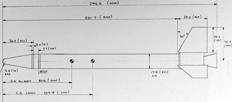
Figure 27. The lay out of a typical test vehicle for solid fuel motors – in the case, a Rook motor. (Dimensions are in inches and mm.) |
UCL in 1979 and became Deputy Director of MSSL in 1985. In 1986 he moved to the Rutherford Appleton Laboratory and became the Associate Director for Space Science in 1993. Moving to the University of Birmingham in 1995, he was appointed Professor of Astrophysics and Space Research and in 1997 became Head of the School of Physics and Astronomy and subsequently Pro Vice Chancellor for Research and Knowledge Transfer. 14 This section was published in an expanded version in issue 5 of the journal Prospero, published by the British Oral History Project.


