Systems and scenarios
ENERGIYA CORE STAGE
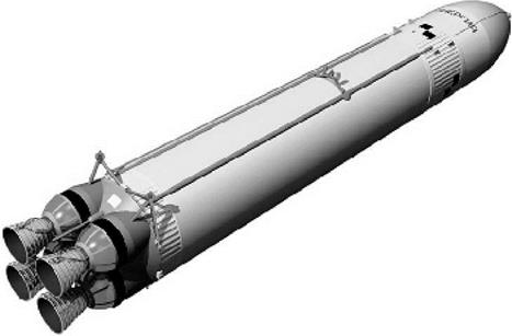
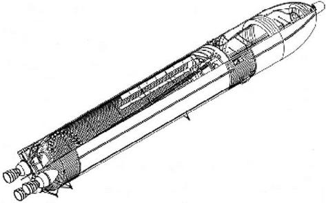
The core stage was designed jointly by NPO Energiya in Kaliningrad and its Volga Branch in Kuybyshev, with manufacturing taking place at the Progress factory in Kuybyshev. With a length of 58.7 m and a maximum diameter of 7.75 m, it was the backbone of the Energiya-Buran stack, providing structural support for attachment with the strap-on boosters and orbiter. It was very similar in design to the Space Shuttle’s External Tank (ET), with the exception of a tail section housing the engine compartment. The core stage was made up of an upper liquid oxygen (LOX) tank, an unpressurized intertank, a lower liquid hydrogen (LH2) tank, and a tail section containing the four RD-0120 engines. The wet mass was 776 tons.
Both the LOX and LH2 tanks were made of a 1201 aluminum alloy. The 552m3 LOX tank could hold about 600 tons of oxidizer. It consisted of a forward ogive section (itself made up of three sections), a cylindrical section (itself made up of two sections), and a spherical aft dome. All sections were welded together. The tank had anti-slosh baffles to dampen any motions of the LOX that might throw the rocket off course. The LOX feed line exited the LOX tank at a 7° angle to the longitudinal axis of the tank to facilitate oxidizer supply during the final moments of the launch. It ran to the tail section right through the LH2 tank. This is a major difference with the Space Shuttle External Tank’s LOX feed line, which emerges from the ET’s intertank area to convey the oxidizer to the aft right-hand ET-Orbiter disconnect umbilical. The LOX feed system had gas accumulators to dampen longitudinal oscillations (“pogo’’). These were located in the lower part of the LOX feed line in the bottom of the LH2 tank and also in the engines’ turbopump inlet ducts.
The intertank was the structural connection joining the liquid hydrogen and oxygen tanks. Flanges were affixed at the bottom and top of the intertank so the two tanks could be attached to it. Also installed in the intertank was the instrumentation for the core stage’s flight control system. Prior to launch the intertank was
|
The Energiya core stage (source: www. buran. ru). |
|
Cutaway drawing of the Energiya core stage (source: Boris Gubanov). |
Energiya core stage 93
purged with nitrogen gas to prevent the build-up of moisture and explosive mixtures of hydrogen and oxygen gas.
The 1,523m3 LH2 tank, which could hold about 100 tons of liquid hydrogen, consisted of spherical aft and forward domes and a large cylindrical section. The tank walls were machined in a waffle-grid pattern, something not employed in the ET hydrogen tank until the introduction of the Super Lightweight External Tank in 1998. Although LH2 is so light that sloshing does not induce significant forces, Energiya’s LH2 tank, unlike that of the ET, did have anti-slosh baffles.
Just like the Shuttle’s ET, the Energiya core stage was covered with a combination of polyurethane spray-on foam insulation (Ripor-2N, PPU-17) and ablative material (PPU-306) for thermal insulation and thermal protection. This reduced boil-off losses during the countdown, maintained the propellants at the proper temperatures for normal engine operation, limited ice formation on the outer surface, and protected the core stage against the flames from the strap-on boosters’ separation motors. The original plan not to apply thermal insulation to the upper part of the LOX tank was abandoned due to fears that ice might break off from that part of the core stage and damage the orbiter’s fragile heat shield. Various non-destructive methods were used to test these materials after they were applied: electric methods to check their thickness, radioisotope techniques for density, and acoustic methods to detect debonding.
Shedding of tank insulation became a big issue in the US after the February 2003 Columbia accident, caused by a piece of foam insulation breaking off the tank and inflicting lethal damage to one of the Reinforced Carbon-Carbon panels on the Shuttle’s left wing. Russian sources do not mention whether Energiya’s foam insulation was less or more prone to shedding simply because this was not a matter of major concern in the pre-Columbia days. Moreover, any foam loss that might have occurred on the two Energiya launches in 1987 and 1988 would have been virtually impossible to photographically document because the first launch took place in darkness and the second in poor weather conditions. Tile damage suffered by Buran on its sole mission has usually been attributed to ice falling off the core stage and the launch pad and not to foam impacts.
Electric power for the core stage was provided by four simultaneously operating turbogenerators driven by air, nitrogen, hydrogen, and helium gas. In order to simplify the design and reduce mass, common plumbing was used for all four gases. Each generator weighed 330 kg and provided 24kWt of power.
The cryogenic propellants were loaded at lower temperatures than on the Space Shuttle (—255°C vs. —253°C for the liquid hydrogen and —195°C vs. —182°C for the liquid oxygen). This made the propellant denser and also significantly reduced boil – off losses. Techniques for subcooling liquid oxygen were pioneered by the Russians with the R-9 missile in the early 1960s, but Energiya marked the first use of subcooled liquid hydrogen. The liquid hydrogen was subcooled by passing it through two double-walled cooling devices in which tubular heat exchangers were immersed in a bath of liquid hydrogen boiling at reduced pressure.
Loading of the core stage began several hours before launch with a slow-fill mode to condition the tanks. When the core stage was 2 percent full, the fueling process was
sped up to 19,000 liters per minute for the liquid oxygen and 45,000 liters per minute for the liquid hydrogen. This fast-fill mode continued until 98 percent of the propellant was loaded. Topping off continued until T — 3m02s for the LOX tank and T — 1m52s for the LH2 tank.
After the start of fueling, electrically powered pumps in the main engines began to circulate the liquid hydrogen in the fuel tank through the four engines and back to the tank to chill down the liquid hydrogen lines, ensuring that the path was free of any gaseous hydrogen bubbles and was at the proper temperature for engine start. The LH2 was recirculated to the tank rather than returned to ground facilities because it loses a lot of pressure during the circulation process. The engines’ LOX lines were also thermally preconditioned, but the LOX used for this purpose was dumped overboard.
In the final minutes of the countdown the tanks were pressurized to maintain their structural integrity during launch, minimize the build-up of volatiles in the tanks, and to prevent cavitation of the main engine low-pressure boost pumps. Pre-launch pressurization was performed with ground-supplied helium and began at T — 2m23s for the LOX tank and T — 1m20s for the LH2 tank. After lift-off the LOX tank was pressurized with hot gaseous oxygen produced by heat exchangers in the main engines and the LH2 tank with gaseous hydrogen tapped from the turbines of the main engine LH2 boost pumps. At lift-off the LOX tank was pressurized to 2.6 atmospheres and the LH2 tank to 3.1 atmospheres. During launch the pressure in the LOX and LH2 tanks was maintained between 1.41-1.55 atmospheres and 2.25-2.39 atmospheres, respectively.
Each tank had a dual-function vent and relief valve at its forward end. It could be opened by ground-supplied helium before launch for venting or by excessive tank pressure for relief during launch. Excess hydrogen gas left the core stage via the intertank area, while excess oxygen gas was directly vented overboard [1].


