Mars-96 campaign objectives
The Mars-96 mission was designed to use an orbiter, two small soft landers, and two penetrators to undertake a comprehensive investigation of the current state and past evolution of Mars by studying physical and chemical processes in the atmosphere, on the surface, and in the interior.
The scientific objectives of the orbiter included obtaining high resolution mapping and spectral imagery of the surface to study its geology, mineralogy and topography, to investigate the gravity field and crustal structure, and to monitor the climate. The spacecraft was also equipped to study the magnetic field, plasma characteristics, and magnetospheric structure. And it had instruments for astrophysieal investigations of gamma-ray bursts, and both stellar and solar oscillations. The penetrators were to obtain images of the surface, undertake meteorological measurements, examine the physical, chemical, magnetic, and mechanical properties of the near-surface regolith. measure the water content of the soil, and measure seismic activity and the heat flow7 from the interior of the planet through the crust. The small landers were to study the vertical structure of the atmosphere and obtain images during the descent to assist in interpreting images taken on the surface, measure elemental, magnetic and oxidant composition of the soil, measure seismic activity, and monitor the local weather for its diurnal, seasonal, and annual variability.
The delays and problems w ith development had been extremely frustrating for the international participants, whose own budgets and schedules were heavily impacted. The failure of the launch and breakup of the spacecraft over the west coast of South America was the final straw for a Russian planetary exploration program that had been struggling against diminishing resources since the Phobos failures in 1988 1989 and the demise of the Soviet bmpire in 1991.
The failures of the Phobos and Mars-96 missions were a heavy loss for planetary exploration. They w’ere ambitious and complex missions aimed at comprehensively studying Mars and the larger of its two moons. They had more engineering systems, more observation platforms, more scientific instrumentation, and more subsidiary
vehicles than any other missions in the history of planetary exploration. The array of measurements they were to have made was simply enormous. If these missions had been successful, the knowledge produced would have been astounding. They were also very international, complex, and expensive. They are missions the like of which will not be experienced in planetary exploration for a long time to come.
Spacecraft:
Orbiter:
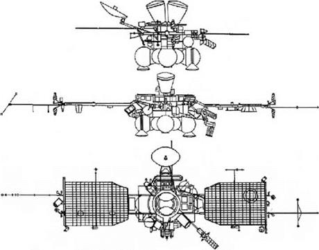
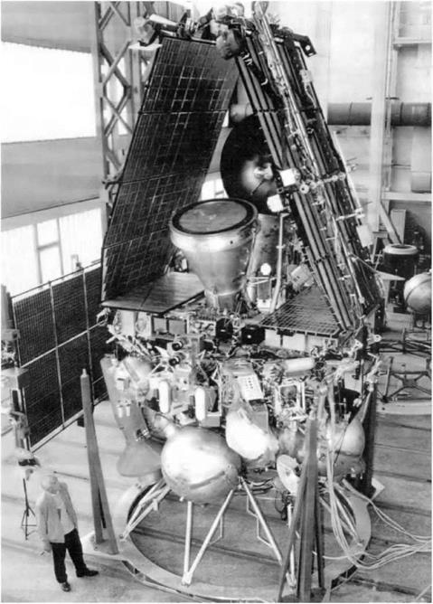
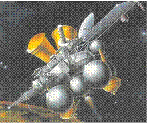
The Mars-96 orbiter was a З-axis stabilized spacecraft based on the Phobos design. A pressurized toroid at the base held the computer and most of the avionics, thermal regulation, communications, batteries and electronics for scientific instruments. The equipment tower was replaced with a flat deck on which equipment and instruments were mounted, including the solar panels and the entry systems for the two landers. The solar panels were larger, and extended out from opposite sides of the deck. They also carried low gain antennas and attitude control nozzles. Many subsystems and scientific apparatus were on the toroid below7 the deck level, including a pair of scan platforms for accurate and stable pointing of cameras and spectrometers. The high gain dish antenna extended off one side of the toroid, oriented perpendicular to the solar panels, and the medium gain antenna w7as on the opposite side. In this case the high gain was not steerable, and provided a communications rate of 130 kbits/s. The thermal control radiators, navigation and Sun and star sensors for the attitude control system were attached to the toroid, including the onboard propulsion system with its propellant tanks and thrusters, as for the Phobos spacecraft. The separable ADU propulsion system (now7 named the Fregat stage) was attached underneath, as before. The two penetrators were mounted on the ADU propellant tanks. The computers were more advanced and supplied by the Europeans who did not trust the Phobos computers after their poor performance. The orbiter carried more than two dozen instruments in addition to the landers and penetrators. Owing to the massive weight of the spacecraft, the Proton could not quite provide sufficient energy for the escape maneuver. After the Block D had released the spacecraft, the Fregat would fire to provide the final increment. The Fregat would perform the midcourse corrections, orbit insertion at Mars, and in-orbit maneuvers before being jettisoned.
Scan platforms were fairly new7 to Russian spacecraft. The 220.7 kg TPS 3-axis platform had its own computer control system, memory, thermal control, navigation camera, and a 53.5 kg payload of remote sensing instruments. The developers had difficulty achieving the stringent pointing and stability requirements, and when the Russians suggested deleting the platform and mounting the instruments on the body of the spacecraft, w hich would have severely limited the science objectives, German engineers were brought in to help to resolve the problems. The 74.2 kg PAIS 2-axis scan platform was simpler, and it carried instruments that had less stringent pointing requirements. The orbiter was to have deployed its landers on approach and then
performed a deflection maneuver to reach the insertion point, whereupon it would put itself into an elliptical orbit. This would be shaped over the first month using several maneuvers to achieve an orbit in which the spacecraft would make four revolutions around the planet while Mars rotated seven times on its axis, because such orbits arc generally quite stable. Once it had achieved an orbit with a periapsis of 300 km and a period of 43.09 hours, it would deploy the penelrators.
The Mars-96 spacecraft was 3.5 meters tall and 2,7 meters wide; 11.5 meters wide with its solar panels deployed.

 |
6,824 kg 2,614 kg 176 kg (2)
241 kg (2)
283 kg (for landers and penetrators) 490 kg
Fuel: 2,832 kg
Hydrazine: 188 kg
Landers:
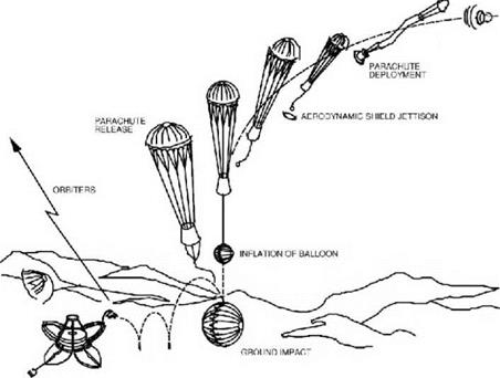
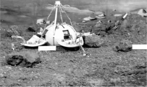
The two landers or ‘small stations’ were similar to those used on the M-71 and M-73 missions but much smaller. They were about the same size as, but lighter than those of Luna 9 and 13. Each lander was approximately 60 cm in diameter and, including the 8 kg payload, was 30.6 kg. For entry, each was contained within a blurt-ended conical ablative aeroshell approximately 1 meter in diameter (Figure 20.3). The total mass of the lander and its entry system was 120.5 kg. Separation was to occur 4 or 5 days prior to orbit insertion, after being given a spin of 12 revolutions per minute for stability. Entry would begin at an altitude of about 100 km at 5.75 km/s and an angle of 11 to 21 degrees. After about 3 minutes, at an altitude in the range 19 to 44 km and a velocity of 200 to 320 m s. the parachute w’ould deploy. The aeroshell would be jettisoned 10 seconds later, and a 130 meter harness would unreel the lander. At about 18 to 4 km and a velocity of 20 to 40 m/s an airbag would inflate around the lander. This was designed to survive an impact at vertical and horizontal rates of about 20 m/s. Immediately upon contact after a descent lasting anything from 6 to 17 minutes, the lander would discard its parachute, and after rolling to a stop the airbag
|
Figure 20.2 Mars-96 spacecraft line drawing (courtesy NPO-Lavochkin). |
|
Figure 20.3 Mars-96 on the integration and test stand. |
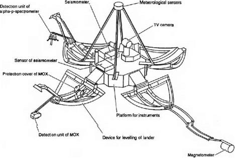
would split open at the seam and he discarded. In a manner similar to the Mars 3 lander four triangular petals would open, each extending about 30 cm from the central base. Three of these petals had springs to deploy instruments away from the lander.
On the surface the lander would draw power from two coffee-cup-sized 220 mW RTGs, a technology that had not previously been used in a Soviet mission but was intended for the rovers, supplemented by NiCd batteries. A lithium battery was used for the descent phase. The uplink and downlink at 2 and 8 kbits/s would use a UHF relay through the orbiter. There was no command capability; downlink was only to initiate transmission. The internal temperature of the lander would be maintained by a combination of insulation and heat from the RTGs and dedicated RHUs; 8.5 W of heater power was available. The expected operating life was about a local year.
In addition to the scientific payload, the landers carried a compact disk provided by The Planetary Society entitled ‘Visions of Mars’ which contained a compendium of knowledge about Mars.
Entry mass: 120.5 kg
Lander mass: 30.6 kg
Payload: 8 kg (~ 5 kg of science)

|
|
|
|
|
|
![]()
|
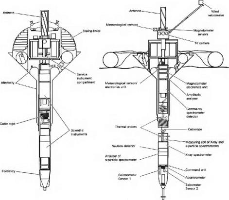
Figure 20.7 Mars-96 penetrators in flight (left) and deployed (right). Penetrators: |
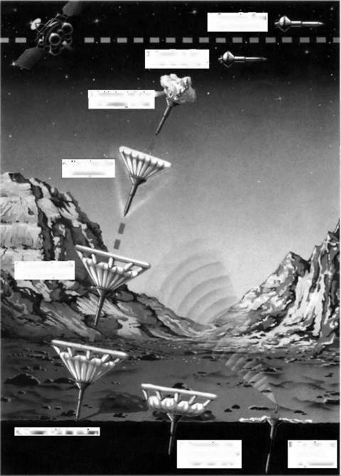
The penetrators were cylinders 2 meters long with a pointed 12 ail diameter forebody and a 17 cm diameter after-body that included a funnel-shaped tail section that broadened to 78 cm diameter. They drew power from a 0.5 W RTG and a 150 watt- hour lithium battery. A total of 4.5 kg of science instruments were distributed in the two sections. Each penetrator was to be released from orbit near apoapsis by pointing the spacecraft in the proper direction and spinning the entry system to 75 revolutions per minute for stabilization prior to release. At a safe distance the orbiter was to make a small diversion maneuver. The penetrator would then fire a solid rocket to reduce its velocity by 30 m/s, jettison this de-orbit motor, and inflate the ballute that was to decelerate the initial phase of its entry when it fell into the atmosphere about 21.5 hours later. Entry would be at a speed of 4.6 to 4.9 km/s and an angle of 12 degrees.
The penetrator would be slowed aerodynamically, then inflate an extension to the ballute in the after-body (Figure 20.8). After a 6 minute descent, it would hit the
|
2. Transfer to the
descent trajectory
i. Initiating inflation M’ of brakititr device J
4. r. ntry into the
atmosphere
5. Descent through
the atmosphere
6. Contact with the surface
7. ![]() Penetration and separation of two petretrator pans
Penetration and separation of two petretrator pans
Figure 20.8 Penetrator entry, descent and landing scheme.
surface at about 75 m/s. The 500 G shock was to be cushioned by a fluid reservoir. The wide after-body was designed to stop at the surface as the fore-bod у separated and penetrated up to 6 meters into the ground, remaining attached by a coiled wire. The aft mast with the antenna, camera, magnetometer, and mcteorologieal sensors was then to extend, and thermal probes would protrude into the soil.
One penetrator was to be sent to a site near one of the landers, and the other to a location at least 90 degrees away to facilitate the triangulation of seismic signals. Communications at 8 kbits/s would be feasible for about 5 to 6 minutes every 7 days through the transmitter on the after-body and would use the relay through the orbiter for uplink and downlink. The expected lifetime was a local year.
Penetrator mass w і engine: 88 kg
Entry mass: 45 kg
Science payload: 4.5 kg
Payload:
Or hi ter:
The orbiter had twelve instruments to study the surface and atmosphere of Mars, seven instruments for plasma, fields, particles and ionospheric composition, and five instruments for solar and asirophysical research. And radio occultalions during limb crossings would give data about the atmosphere. The instruments were on the sides of the spacecraft, on one or other of the two scan platforms, and on the solar panels. The three optical instruments of the ARGOS package were on the З-axis I PS scan platform along with the navigation camera, and the SPICAM, EVRIS and PHOTON instruments were on the simpler 2-axis PAIS scan platform.
Remote sensing of the surface and atmosphere:
1. Multifunctional stereoscopic high resolution TV camera (ARGOS HRSC. Germany-Russia)
2. Wide-angle stereoscopic TV camera (ARGOS WAOSS, Germany-Russia)
3. Visible and infrared mapping spectrometer (ARGOS OMEGA, Eranee – Russia-Italy)
4. Planetary infrared Fourier spectrometer (PFS, Italy-Russia-Poland-France – Germany-Spain)
5. Mapping radiometer (TERMOSKAN, Russia)
6. High resolution mapping spectrophotometer (SVET, Russia-USA)
7. Multi-channel optical spectrometer (SPICAM, Belgium-France-Russia)
8. Ultraviolet spectrophotometer (UVS-M, Russia-Germany-France)
9. Long wave radar (LWR, Russia-Cermany-USA-Austria)
10. Gamma-ray spectrometer (PHOTON, Russia)
11. Neutron spectrometer (NElJ I RON-S, Russia)
12. Quadrupole mass spectrometer (MAK, Russia-Finland)
The West Germans supplied the 21.4 kg high resolution HRSC camera and the hast Germans the 8.4 kg wide angle WAOSS camera. After the reunification of that nation the instruments were combined into a single project. Each was a push-broom scanner using parallel linear arrays of 5,184 pixel CCDs. The narrow angle camera had nine arrays for multispectrak photometric, and stereoscopic imaging. The wide angle camera had three arrays for stereoscopic imaging. The best resolution would be 12 meters for the narrow angle camera and 100 meters for the wide angle camera. Because the altitude and velocity of the spacecraft would vary during the periapsis encounters in an elliptical orbit, the CCD integration times could be tailored over the long scans. The cameras on the TPS platform had an extensive 25.3 kg MORION-S onboard processing unit which incorporated a 21 kg solid-state memory system built in cooperation with ESA with a capacity of 1.5 gigabits to reduce the transmission requirements. These data acquisition resources were shared with other instruments. Also on the TPS platform was the 23.7 kg OMEGA visible and infrared mapping spectrometer to measure atmospheric composition and map surface composition.
The 28 kg TERMOSKAK instrument from Phobos was re-flown to measure the thermal properties of the regolilh. The 12 kg SVET mapping spectrophotometer was to analyze the spectrum of the surface and aerosols. The 20 kg PHOTON gamma – ray spectrometer would map the elemental composition of the surface, and the 8 kg NEUTRON-S neutron spectrometer would determine ice and water abundances. The 35 kg LWR would probe the near-surface layer to measure vertical structure and ice deposits. The 25.6 kg PES was to make atmospheric profiles of carbon dioxide, and measure atmospheric temperatures, winds, and aerosols. The 46 kg SPICAM would use solar and stellar occultations to produce vertical profiles of water vapor, ozone, oxygen, and carbon monoxide. The 9.5 kg UVS-M was to map atomic hydrogen, deuterium, oxygen and helium in the upper atmosphere of Mars and the interstellar medium. The 10 kg MAK mass spectrometer was to measure the composition and distribution of ions and neutrals in the upper atmosphere.
Space plasma and ionosphere:
1. Energy-mass ion spectrograph and neutral particle imager (ASPERA-C. Sweden-Russia-Finland-Poland-USA-Norway-Germany).
2. Fast omni-directional non-scanning energy-mass ion analyzer (EON EM A. UK-Russia-Czech Republic-France-Ireland).
3. Omnidirectional ionospheric energy-mass-spectrometer (DYMIO, France – Russia-Cermany-USA).
4. Ionospheric plasma spectrometers (MARIPROB, Austria-Belgium-Bulgaria – Czech Republic-Germany-Hungary-1 reland-Russia-USA).
5. Electron analyzer and magnetometer (MAREMF. Austria-Belgium-France – Germany-Great Britain-Hungary-Ireland-Russia-USA).
6. Plasma wave instrument (ELISMA, France-Bulgaria-Great Britain-ESA – Poland-Russia – Ukraine).
7. Low-energy charged particle spectrometer (SLED-2, Ircland-Czcch Repub – lic-Cermany-IIungary-Russia-Slovakia).
The 12.2 kg ASPERA instrument was to measure the energy distribution of ions and fast neutrals. The 10.7 kg EON EM A ion analy/er would measure the dynamics and structure of the upper atmosphere plasma. The 7.9 kg MARIPROB and 7.2 kg DYMIO instruments would complement these instruments. The 12.2 kg MAREMF instrument would analyze plasma electrons and it carried two lluxgate magnetometers to measure magnetic fields in interplanetary space and in orbit of Mars. The 12 kg EL-ISM A instrument was to measure plasma waves in the Martian environment. It consisted of three Langmuir probes and three search coil magnetometers. In addition to probing the surface of the planet the LWR radar was also to be used to measure the distribution of electrons in the ionosphere and how this interacted with the solar wind. The 3.3 kg SLED-2 instrument was to measure low energy cosmic rays during the interplanetary cruise and in the Mars environment.
Solar physics and astrophysics:
1. Precision gannna-ray spectrometer (PCS, Russia-USA).
2. Cosmic and solar gannna-ray burst spectrometer (LILAS-2, Russia-France).
3. Stellar oscillations photometer (EVRIS, France-Russia-Austria)
4. Solar oscillation photometer (SOYA. Ukraine-Russia-France-Switzerland)
5. Radiation dosage monitor (RADIUS-M, Russia-Bulgaria-Greece-USA – France-Czech Republic-Slovakia)
The 25.6 kg PCS gamma-ray spectrometer was intended to examine solar flares during the interplanetary cruise and then measure gannna-ray emission when in orbit around Mars. The 5 kg LILAS-2 instrument would locate celestial gamma-ray bursts in conjunction w’ith several spacecraft in Earth orbit and Ulysses in deep space. The celestial sources were also to be examined by using Mars occultation observations. The 1 kg SOYA and 7.4 kg EVRIS photometers were to make helioseismology and astroseismology measurements respectively. SOYA was body mounted but EVRIS was on the 2-axis scan platform. The RADIUS-M radiation dosimeter was carried to obtain data pertinent to prospective future human Mars missions.
Landers:
Entry and descent:
1. Descent imager (DESCAM, France-Finland-Russia)
2. Three-axis accelerometer plus sensors for temperature and pressure (DPT Russia)
The lander had a suite of sensors and a descent imager. DESCAM was mounted on the bottom of the lander to obtain imagery to provide context for the panorama that would be taken following landing. It had a 400 x 500 pixel CCD and was to be detached 2 minutes after landing, just before the airbag was discarded. The DPI had an accelerometer and temperature and pressure sensors to provide vertical profiles of temperature, pressure and density during entry and descent, and the dynamics of the landing. It was mounted outside the lander bay under one of the petal covers, so that descent data was convoluted with flow dynamics during descent.
Surface:
1. Panoramic camera on a central mast (PANCAM. Russia-France-Finland)
2. Meteorology instrument system on a 1-meter tall mast for temperature, pressure, humidity, wind, and optical depth (MIS, Finland-France-Russia)
3. Seismometer, magnetometer and inclinometer (OPTIMISM, Francc-Ger – many – Russia)
4. Alpha, proton and x-ray spectrometer for soil elemental analysis (APX. Germany-Russia-USA)
5. Oxidant sensor (MOX, USA-Russia)
At the top of the station shell, the lander carried a PANCAM scanning photometer camera similar to those on the earlier Mars landers to provide a 360 x 60 degree panorama composed of 6,000 x 1,024 pixels. A deployable overhead mast supported the MIS meteorology package with sensors for temperature, pressure and humidity, an ion anemometer for wind, plus an optical-depth sensor. The ODS optical sensor in this package was supplied by the French and measured direct Sun and scattered light at the zenith in three narrow bands at 270, 350. and 550 nm, and one broad band from 250 to 750 nm. The DPI package measured temperatures and wind velocities on the surface. Three of the petals contained instruments for deployment to the surface: the OPTIMISM instrument containing a seismometer, inclinometer and З-axis lluxgate magnetometer; the APX backseat ter analyzer to determine elemental abundances in the soil; and the MOX experiment. The latter was a colorimetric soil analyzer that had reactant spots sensitive to different types of oxidants. Supplied by the IJS it was developed in less than a year, weighed only 0.Я5 kg, and had its own power supply and data storage. Its function was to test the inference from the Viking landers that the soil was rich in oxidants and hence inimical to life.
Penetvatovs:
After-body above surface:
1. Television Camera (TVS, Russia)
2. Meteorological sensors for temperature, pressure, humidity, wind and opacity (MEKOM, Russia-Finland-USA)
3. Magnetometer (IMAP-6, Russia-Bulgaria)
After-body below surface:
1. Gamma-ray spectrometer for soil analysis (PEGAS, Russia)
2. Temperature sensor for heat flow (TERMOZOND Part 1, Russia)
Fore-body:
1. Seismometer for interior structure (KAMERTON, Russia-Great Britain)
2. Accelerometers for soil mechanics (GRUNT, UK-Russia)
3. Temperature sensor for heat flow (TERMOZOND Part 2, Russia)
4. Neutron detector for water detection (NEUTRON-P, Russia)
5. Alpha-proton spectrometer for soil analysis (ALPHA, Russia-Cermany)
6. X-ray fluorescence spectrometer for soil analysis (ANGSTREM, Russia)
The GRUNT accelerometer in the fore-body was to measure the properties of the surface during impact and penetration. The KAMERTON seismometer would search for Martian activity. The TERMOZOND thermal probes would measure heat flowr and provide data for thermal diffusivity and heat capacity. The gamma – ray, alpha, proton, neutron, and x-ray spectrometers would analyze the soil chemistry including its water content. Remaining above the surface on the afterbody, the TVS 2,048 pixel linear camera would take a panoramic image of the site, the MEKOM package would monitor the temperatures and winds, and the IMAP-6 magnetometer would measure the local magnetic field.
Mission description:
Mars-96 was to have arrived at Mars in September 1997 on a direct trajectory about 10 months after launch. The small surface stations were to have been released 4 or 5 days out from the planet for direct atmospheric entry. The spacecraft would execute a deflection maneuver for its orbital insertion point. By this time the Mars ephemeris was very well know7n, so the complex optical navigation and close-in release of the M-71 and M-73 missions was not required. Three landing sites were selected for the landers, the two primary ones being at 41.31CN 153.77:W in Arcadia and at 32.48CN 163.32;W in Amazonia, with the backup at 3.65:,N 193 W.
At insertion the spacecraft would perform a braking maneuver into an initial orbit of 500 x 52,000 km, and this would be reduced in stages to a 43.09 hour 7:4 Mars synchronous orbit at 106.4 degrees inclination with a 300 km periapsis.
The two penetrators were to have been deployed within 7 to 28 days, one targeted for Arcadia and the other at least 90 degrees away in Utopia Planitia to provide a good baseline for seismometry. The Eregat would be jettisoned after the deployment of the penetrators. Orbit maintenance would then be the task of the smaller onboard propulsion system.
At the start of the orbital mission communications sessions with the landers and penetrators were expected to be through the orbiter approximately once per day for 20 minutes each. One small orbit correction of about 1 to 2 m s w ould be required each month to maintain visibility with the surface elements, w’hose nominal lifetime was to have been one local year or roughly two terrestrial years.
The spacecraft was launched on the optimal day of the window’, November 16, 1996, and reached Earth orbit after the first firing of the Block D. If this stage had fired properly to initiate the escape maneuver, the Eregat propulsion system on the spacecraft would have provided the final increment required to reach Mars. It seems that cither the Block D-2 did not fire or it shut down after only 20 seconds, perhaps owing to an inappropriate command from the spacecraft, which was in control of it. The logic of the situation then caused the spacecraft to separate and fire its Hregat as if to complete the escape maneuver. However, this burn left it in an 87 x 1.500 km elliptical orbit. With its periapsis inside the atmosphere the spacecraft was doomed. The Block D-2 stage entered the atmosphere at some time between 00:45 to 01:30 IJT on November 17 and crashed into the Pacific between the Chilean coast and Easter Island. A day later, the spacecraft was spotted re-entering the atmosphere as a fireball over southern Chile, and is believed to have crashed in the Andes mountains of Chile near the border with Bolivia. It was carrying 270 grams of plutonium-238 in 18 pellets as part of the landers and pcnctrators. Designed to withstand heat and impact, these probably survived re-entry. Searches were made but the spacecraft was never found.
The failure occurred at the second ignition of the Block D-2 upper stage w hile the spacecraft was out of range of Russian ground stations. Owning to budget limitations the Russians had no tracking ships in the Pacific. The lack of telemetry data during critical parts of the escape phase of the mission precluded identification of the cause of the failure, and in particular w hether it w as due to failure of the Block D-2 upper stage or to a malfunction of the controlling spacecraft. It was an abysmal situation.
Results:
None.


