The Apollo zone
RECONNAISSANCE FLIGHTS
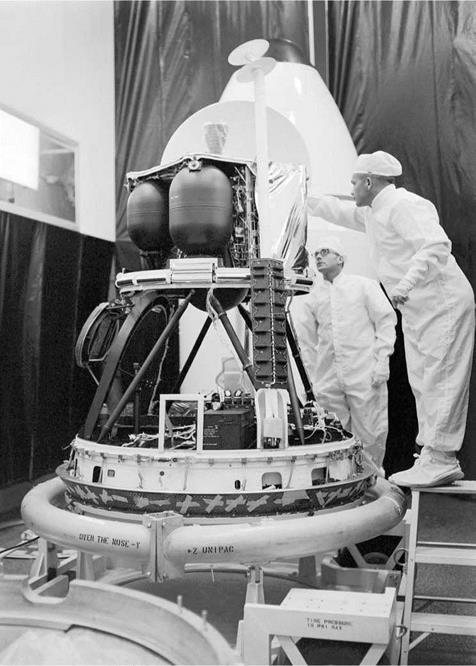
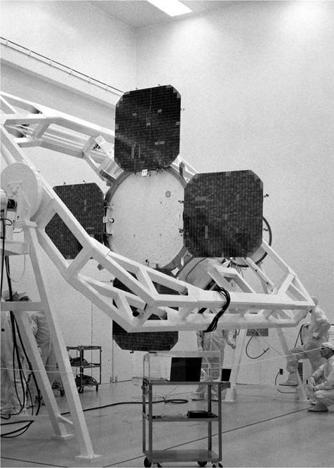
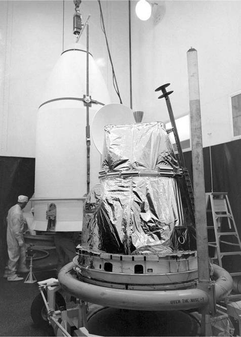
Only 28 months elapsed between James Webb approving the Boeing contract for Lunar Orbiter and the first mission. It had been hoped to launch on 11 July 1966, but Eastman Kodak was late in delivering the photographic system and the launch was rescheduled for 9 August. At the Cape, the Air Force made available Hangar S for the project. The photographic system was installed on 1 August, and the next day the spacecraft was mated with its Atlas-Agena D on Pad 13. At this point, a Deep Space Network facility at the Cape verified the spacecraft’s communication system.
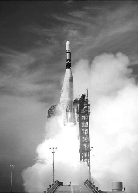
The countdown on 9 August was scrubbed at T-7 minutes owing to an anomaly with the Atlas, but liftoff occurred at 19:26:01 GMT on 10 August. The spacecraft’s launch mass was 387 kg – which was at the top end of the launcher’s capability for a deep-space mission. The Agena made a 154.5-second burn to achieve insertion into parking orbit at an altitude of 190 km at 19:34:44. It reignited at 20:02:35 to perform the 89-second translunar injection manoeuvre.
Following its release at 20:06:48, Lunar Orbiter 1 deployed its solar panels and antennas, then acquired the Sun for the first step towards adopting its cruise attitude. Some 6 hours into the translunar coast, the spacecraft was ordered to roll in order to locate the star Canopus, but it failed to lock on. The sensor was being distracted by sunlight reflecting off the vehicle’s structure – a possibility that really ought to have been ‘designed out’. The vehicle was commanded to turn to point the sensor at the Moon to provide a second point of reference to initialise the inertial system.
The midcourse manoeuvre of 38 m/s was achieved by a 32-second burn started at 00:00 on 12 August. When its interior began to overheat, the vehicle was instructed to swing its main axis 36 degrees off-Sun. This thermal problem came as a surprise, because Boeing had subjected the design to thorough testing in the vacuum chamber at its Kent Test Facility in Seattle. The Canopus sensor was finally able to lock on at 13:50 on 13 August.
The trajectory was so accurate that the vehicle arrived within 10 km of the desired
orbit insertion point. The command for the insertion manoeuvre was sent at 15:23 on 14 August, after a cruise of 92 hours as against 66 hours for Ranger. After adopting the requisite attitude, the spacecraft began the burn at 15:34, firing its engine for 579 seconds in order to slow down by 790 m/s and enter a 190 x 1,860-km orbit that was inclined at 12.2 degrees to the lunar equator and had a period of 3 hours 37 minutes. As viewed from an imaginary vantage point above the Moon’s north pole, the orbit was anticlockwise. Shortly after insertion, the vehicle disappeared around the Moon’s trailing limb.
On 15 August Lunar Orbiter 1 read out the pre-exposed test frames on the leader of its film strip. These had been read out during ground trials at Goldstone to verify the functionality of the scanning and communication system. This in-flight readout was to confirm that the entire apparatus, both in space and on Earth, was functioning properly. By now, the thermal problem had become acute. The paint on the base of the vehicle was meant to absorb heat while exposed to sunlight and radiate it back to space while in the shadow of the Moon, but it seemed the pigment was deteriorating. However, on 18 August an electrical issue had the beneficial side – effect of easing this overheating problem.
The phase of the Moon was ‘new’ on 16 August; ‘first quarter’ would occur on 23 August and ‘full’ on 31 August. As the alignment of the spacecraft’s perilune would remain fixed relative to the stars, the longitude of perilune would migrate westward at a rate of 12 degrees per 24 hours as the Moon travelled around Earth. This meant that the spacecraft could photograph a succession of sites along the equatorial zone with the Sun at essentially the same elevation in the sky. The Canopus sensor would routinely recalibrate the inertial system to ensure that the camera was accurately aimed.
After advancing the film to its start point, the camera snapped its first pictures on 18 August. It viewed Mare Smythii, near the equator on the eastern limb. Although outside the Apollo zone, this area was of interest for selecting landmarks to assist in Apollo orbital navigation. In this case, the spacecraft was at an altitude of 246 km, its velocity relative to the surface was 6,400 km/hour, the shutter setting was 1/50th second, and the frame pairs were taken at 10-second intervals. These frames were processed and 5 hours later were scanned travelling forward through the system. The M frames were of excellent quality, but it seemed that the focal-plane shutter of the narrow-angle optics was out of synchronisation with the V/H sensor, smearing the H frames. To investigate the problem, it was decided to take additional pictures using different shutter speeds, both with and without the V/H sensor operating. The results confirmed the sensor to be inoperative. A further test was made in which the output voltage of the sensor was increased in the hope of engaging the shutter, but this did not work. An analysis of the telemetry showed that the logic control circuitry of the focal-plane shutter was susceptible to electromagnetic interference that made it fire at the wrong point in the motion-compensation cycle, and this was a problem which could not be overcome in flight.
Since the H frames were essential to addressing Apollo’s requirements and they would not be able to be provided, Jack McCauley and Lawrence Rowan of the US Geological Survey recommended that the high perilune be retained in order to
|
|
|
|
|
||
|
|
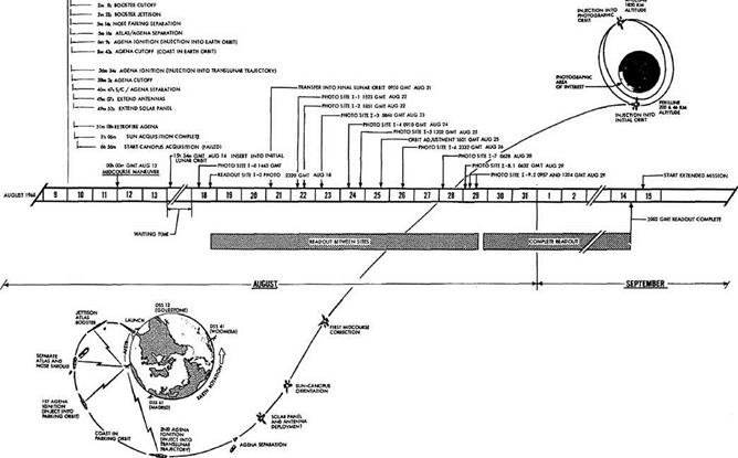
The Lunar Orbiter 1 mission timeline.
obtain wide-area mapping at a resolution of about 25 metres, to improve coverage of the majority of the Apollo zone at a definition better than that of a telescope. Doing so would enable other candidate sites to be re-evaluated prior to drawing up the target lists for subsequent Lunar Orbiter missions. The Bellcomm advisors were in agreement. But Clifford Nelson, the Project Manager at Langley, and his Boeing counterpart, Robert Helberg, argued that if the perilune were lowered then the increased rate of motion presented to the V/H scanner might induce the shutter to synchronise, in which case the mission would be able to proceed as planned. And so it was decided to make a 22.4-second, 40-m/s burn at 09:50 on 21 August to lower the perilune to 58 km.
As the spacecraft was approaching apolune, shortly prior to the perilune – lowering manoeuvre, it took a picture of the far-side. At an altitude of 1,497 km there was no need for V/H motion compensation, and when the H frame was read out it proved to be of excellent quality, confirming that the optics were correct. At this point, it was discovered that the Bimat strip was sticking to the processing drum. The plan had been to obviate this problem by not letting the Bimat remain immobile for more than 15 hours, and to shoot a frame-pair once every four orbits with the thermal door shut if no target was scheduled. The remedy was to reduce the time that the Bimat was immobile. The increased number of frames for this maintenance task meant revising the photographic mission. The most important targets would still receive the planned 16-exposure blocks, but others would get only half this number.
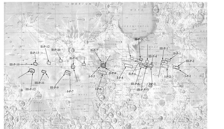
Lunar Orbiter 1 was to photograph nine primary targets in the southern part of the Apollo zone, seven secondary targets and the far-side from high altitude. At this stage in the reconnaissance process, however, each primary target spanned an area in which there might prove to be tracts which could be nominated as potential Apollo landing sites.
The primary targets were labelled by Roman numeral ‘I’ (for the first mission), ‘P’ for primary, and an Arabic number in a sequence progressing generally from east to west. In this scheme, the Mare Smythii area was I-P-0.
In terms of classifications:
I, mare
A, average mare
B, dark mare
C, ridged mare
D, rayed mare
II, upland
A, highland basins
B, subdued uplands
C, upland plains
D, sculptured highlands
III, craters
A, well formed
B, subdued
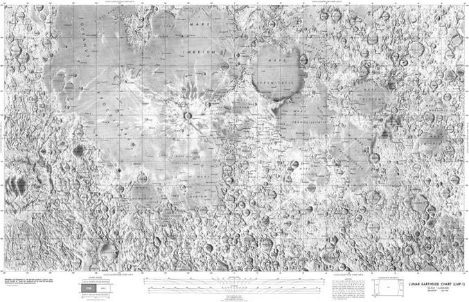
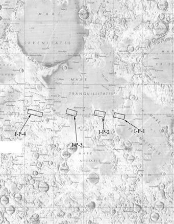
A map of the near-side of the Moon on a scale of 1:5,000,000 derived from imagery produced by the Lunar Orbiter missions.
|
|
IV, structural features
A, ridges
B, domes
C, rilles
the planners had the following to say about the primary sites:
Site I-P-1 (0.9°S, 42.3°E)
This site is within the lowlands of the western extreme of Mare Foecunditatis, and a portion of the eastern extremity of the central highlands. The inclusion of dark mare, moderately light mare and uplands makes this a valuable terrain calibration area. The 1-metre relative roughness of the two mare types is of special interest. The possible detection of generic relationships in the contact between the uplands and dark mare is of particular importance scientifically. The mare units are potential Apollo landing sites. (Rating A)
Site I-P-2 (0.2°S, 36.0°E)
A highland site bordering the southeast part of Mare Tranquillitatis. Significant terrain calibration data is expected for the mare and upland units II-A and II-B. Potential Apollo landing sites may be revealed here. (Rating B)
Site I-P-3 (0.3°N, 24.9°E)
This site in southwestern Mare Tranquillitatis is crossed by a ray. Data on the small-scale roughness and morphology of this area should be obtained. It is a potential Surveyor and Apollo landing site. (Rating B)
Site I-P-4 (0.0°, 12.9°E)
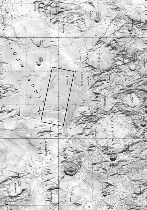
This site is located in the central highlands between Mare Tranquillitatis and Sinus Medii. High-resolution photography of terrain units II-A, II-B, II-C and II-D will provide data to define the 1-metre-resolution roughness of the upland areas. This is a potential Surveyor and Apollo landing site. (Rating A)
Site I-P-5 (0.4°S, 1.3°W)
Located in the southwestern portion of Sinus Medii, this is an especially good example of a smooth mare with low subdued ridges, which are important in the evaluation of the mare origin and development. This has high potentiality as a Surveyor and Apollo landing site. (Rating B)
Site I-P-6 (4.0°S, 2.9°W)
This area in the northern sector of the central highlands is important to terrain calibration by offering high-resolution photography of upland unit II-D as well as the deformed crater floor that is a previously selected Surveyor landing site. It is expected that this coverage will be valuable when bearing-strength data becomes available for the major terrain types. (Rating A)
Site I-P-7 (3.8°S, 22.8°W)
This site located between the craters Fra Mauro and Lansberg is a moderately good example of a mare with low sinuous ridges, small craters and a light ray. It should provide important information regarding the development of older mare surfaces, and their characteristic morphology. It is a previously selected Surveyor landing site. (Rating B)
Site I-P-8.1 (3.0°S, 36.5°W)
This site in the southeast part of Oceanus Procellarum is a superior example of a relatively straight mare ridge, and is of particular importance in the definition of 1-metre-resolution roughness. It is an opportunity to investigate the generic processes concerned with the development of this mare morphology. It is a highly rated Surveyor landing site. (Rating A)
Site I-P-9.1 (2.3°S, 43.4°W)
This is the Surveyor 1 landing site. The location was changed on the basis of later refinement of the position of the lander, relabelled I-P-9.2a and I-P-9.2b, and scheduled for two successive orbits.
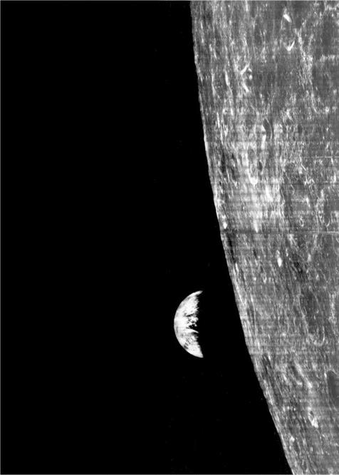
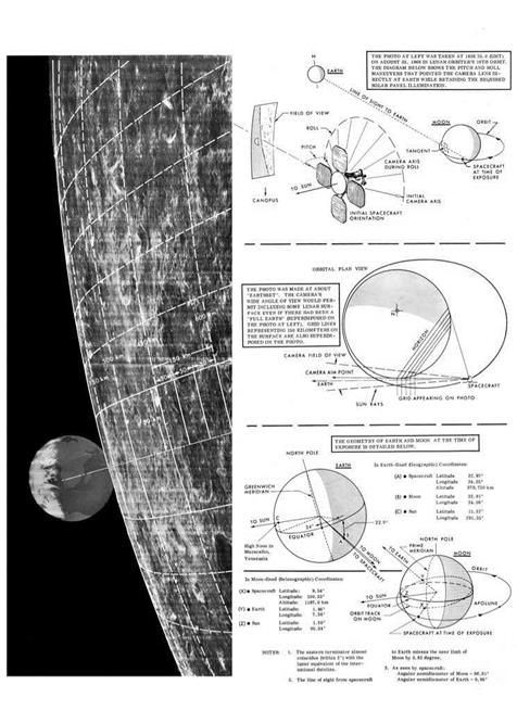
The first photography of a site in the Apollo zone was a 16-exposure sequence of I-P-1 taken on 22 August. The possibility of photographing Earth on the limb of the Moon had been discussed a year before the spacecraft was launched, but it was not made a mission requirement. On 22 August NASA representatives suggested that it be attempted, even though it would require the vehicle to adopt an unusual attitude. Robert Helberg, the Boeing manager, considered the impromptu manoeuvre to be an unnecessary risk because immediately after taking the picture the vehicle would pass beyond the limb and would have to re-establish its normal attitude out of contact with Earth. The company was understandably reluctant, because a large part of the bonus of its ‘incentive’ contract depended on completing the primary mission. Floyd Thompson, Clifford Nelson and Lee Scherer were in favour. Boeing relented when NASA agreed to compensate it if the vehicle were lost as a result of the experiment. At an altitude of 1,198 km, climbing towards apolune on 23 August, Lunar Orbiter 1 approached the trailing limb of the Moon as viewed from Earth. It turned to point its main engine perpendicular to the line of the limb, and then rolled until the camera’s oblong H frame paralleled the limb. The shutter was fired at 16:36:28.6 GMT. The wide-angle view showed Earth as a tiny crescent against the limb, and also provided a magnificent view of the far-side crater Tsiolkovsky. The H – frame was much more dramatic, showing ‘Earth set’ against the cratered lunarscape. This was prominently featured by newspapers. A somewhat less impressive picture of Earth was taken at 07:15:00.9 on 25 August.
A 3-second, 5.4-m/s burn at 16:01 on 25 August lowered the perilune to 40 km to increase the motion of the image across the narrow-angle shutter, but the V/H sensor remained inoperative. At 13:23 on 29 August the spacecraft began the photographic sequence for I-P-9.2b, the final target on its list. The Bimat strip was cut at 18:14 on 30 August, and the full readout by rewinding the film began at 20:42. This process was finished at 21:18 on 16 September. Of the total of 205 frame-pairs, 38 had been obtained in the initial orbit. All nine primary targets had been photographed at lower altitude. Despite the loss of the high-resolution pictures of the primary targets, the mission was judged a successful engineering test of a new spacecraft which had produced some useful imagery.
|
|
Its primary mission over, Lunar Orbiter 1 flew on to gather additional selenodesy, micrometeoroid and radiation data – all eagerly sought by the Apollo planners. The radio tracking of the spacecraft also served to certify the facilities and procedures of the Manned Space Flight Network at lunar distance.[31] By 28 October the condition of the vehicle had deteriorated – its battery was failing as a consequence of persistent overheating, its transponder was dropping out intermittently, its inertial reference unit was becoming unreliable, and the nitrogen for its attitude control thrusters was almost exhausted. To lose control of the communications system would risk radio interference with its successor, so on 29 October Lunar Orbiter 1 was deliberately crashed onto the far-side. In its 8 weeks in space, the micrometeoroid experiment had reported no hits at all. Because of the persistent thermal problems, the white paint for the base of the vehicle was modified for the next mission.
The Lunar Orbiter Photo Data Screening Group of specialists from JPL, Langley, the Manned Spacecraft Center, Boeing, Bellcomm, the Army Map Service, the Air Force Chart and Information Center, NASA headquarters and the US Geological Survey studied Lunar Orbiter 1’s M frames to test the hypothesis that terrain which appeared smooth at the resolution of a telescope was probably smooth in finer detail. They also estimated the cratering of the different types of terrain, first by counting the craters down to the limiting resolution and thereafter using the photogrammetry technique. And, of course, photoclinometry was used to measure slopes. With Gene Shoemaker busy with Surveyor, the analysis at the US Geological Survey was led by Jack McCauley. For a spacecraft making a powered descent directly from translunar trajectory the target was a 60-km-diameter circle, but an Apollo lander descending from lunar orbit was expected to be able to be more accurate. But because pin-point accuracy could not presumed, at least not for the early missions, Apollo targets were ellipses with their major axes aligned along the line of approach. The US Geological Survey produced terrain and geological maps for smooth-looking areas which were large enough to accommodate ellipses of sizes corresponding to differing degrees of landing accuracy.
Taking into account the ‘ground truth’ provided by Surveyor 1 at I-P-9.2, the nine primary targets were rated in terms of increasing roughness as follows:
I-P-9.2
I-P-3
I-P-1
I-P-7
I-P-8.1
I-P-5
I-P-6
I-P-4
I-P-2
|
Table 11.1 – Lunar Orbiter 1 orbital manoeuvres and photography
Notes: (1) Engineering exposures have been omitted. (2) The В-sites were previews of targets being considered for the forthcoming ‘В’ mission. |
On 6 May 1966 representatives of Lunar Orbiter, Surveyor, Apollo and Bellcomm had met at Langley in order to plan the ‘B’ mission. Whereas the inclination of the first spacecraft’s orbit was chosen to facilitate vertical photography of targets in the Apollo zone south of the equator, the inclination of the second spacecraft’s orbit was to inspect targets north of the equator. As planning for this mission began before the first mission flew, the targets were drawn from those chosen by the Surveyor/Orbiter Utilisation Committee from the list submitted by Jack McCauley in August 1965 on the basis of telescopic studies. A total of 13 primary and 17 secondary targets were selected, each of which was to receive one pass. The secondary areas were not under consideration for the early Apollo landings, but were considered to be of ‘scientific interest’. The photographic system had to advance at regular intervals to prevent the Bimat from sticking. In accordance with Boeing’s procedure, for Lunar Orbiter 1 the film had been advanced with the thermal door closed. But Tom Young at Langley and Ellis Levin at Boeing had devised a procedure for doing this with the door open, and a schedule had been written to allow this maintenance function to provide useful pictures. The ‘B’ plan was approved by the Surveyor/Orbiter Utilisation Committee on 1 June.
In late September, however, the planners convened to review the target list in the light of the results of the first mission. One factor that influenced Apollo planning was Ranger 7’s pictures of bright rays from Copernicus and Tycho crossing Mare Nubium. If (as was suspected) all rays were highly cratered, then this would argue against such areas being considered as landing sites. To test this hypothesis, Lunar Orbiter 1 had imaged a faint ray crossing Mare Tranquillitatis that originated from Theophilus, a prominent crater in the highlands to the south. There was no H frame coverage to confirm it, but the M frame suggested that the cratering was insufficient to rule out this site (I-P-3) as a potential Apollo site. It was decided to revise the ‘B’ mission to further study this issue by inspecting rays crossing Oceanus Procellarum between the craters Copernicus and Kepler. On 29 September the Surveyor/Orbiter Utilisation Committee, having reviewed the crater densities and slopes derived from Lunar Orbiter 1’s M frames, recommended that eight areas be carried over to Lunar Orbiter 2 for study at higher resolution. Apart from the deletion of the high-perilune photography of the eastern limb, in purely operational terms the ‘B’ mission was to be a repeat of its predecessor.
After serving as the backup for the first mission, Lunar Orbiter 2 had been stored. Once modified, it was mated with its launch vehicle on 31 October and a countdown test that concluded on 3 November certified it ready for flight.
Lunar Orbiter 2 was launched at 23:21 GMT on 6 November 1966. After coasting in parking orbit for 14 minutes, the Agena performed the translunar injection burn. Parts of the spacecraft’s surface had been painted black to reduce the opportunity for reflected sunlight to dazzle the Canopus sensor, and at 08:21 on 7 November this locked on without incident. At 19:30 on 8 November the spacecraft fired its engine for 18 seconds for a 21-m/s midcourse manoeuvre. The modified paint on the base of the vehicle eliminated the thermal problem that had marred the first mission. The 612-second, 830-m/s burn at 20:26 on 10 November put the spacecraft into an initial orbit of 196 x 1,871 km that was inclined at 12.2 degrees to the lunar equator and had a period of 3 hours 38 minutes. At 22:58 on 15 November a 17.4-second 28-m/s burn lowered the perilune to 50 km. The photography began on 18 November. The phase of the Moon was ‘new’ on 12 November; ‘first quarter’ would occur on 20 November and ‘full’ on 28 November.
Several modifications had been made to the photographic system. In particular, an integrating circuit had been added to the focal-plane shutter control logic to ensure that an output signal was not an electrical transient but a genuine command pulse; and a filter had been added to the 20-volt power line in order to minimise electromagnetic interference and spurious triggering of the circuits. An early check showed that the V/H sensor was operating correctly. As the spacecraft’s perilune migrated west with the terminator, on 20 November it photographed site II-P-5 in Mare Tranquillitatis in search of Ranger 8’s impact point. On the next revolution it
|
|
inspected the nearby I-P-3 target that had been rated highly on the basis of Lunar Orbiter 1’sM frames, thereby obtaining the H frames which would be required for a more detailed evaluation.
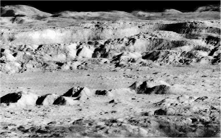
The most striking image of any mission to date was taken on 24 November as one of the maintenance exposures. Douglas Lloyd of Bellcomm had suggested early in planning that at this point the opportunity should be taken to obtain an oblique view of Copernicus, and this had been agreed as II-S-12. The vehicle was at an altitude of 46 km, and the 100-km-diameter crater was some 240 km away to the north of the ground track. The illumination was ideal for discerning the nature of the local topography – on the horizon beyond the crater was a section of the Carpathian Mountains, whose peaks stand 1,000 metres above the surrounding terrain. This was the first view to present the Moon as it would be seen by an astronaut in low orbit. When the picture was issued to the press, the New York Times journalist Walter Sullivan described it as “one of the greatest pictures of the century”.
Another such maintenance exposure, II-S-15, was an oblique of the Marius Hills in the western portion of Oceanus Procellarum, which gave the impression of being volcanic domes.
The photography concluded on 25 November, after all 30 of the specified targets had been documented. The high-gain transmitter failed on 6 December, one day before the readout was to end. Although this resulted in the loss of three M and two H frames of target II-S-1 in the eastern part of Mare Tranquillitatis, these had been taken at the start of the mission and their loss was not serious because some of them had been read out as part of the verification process as the film was running forward. The mission provided a number of high-quality pictures of the far-side. As regards the rays crossing the maria, while the results showed these were not always heavily cratered, II-S-11 located between Copernicus and Kepler was certainly ruled out for Apollo. The micrometeoroid experiment reported three hits. As the first mission had reported no hits, it was speculated that Lunar Orbiter 2 had been exposed to the annual Leonid meteor shower.
On 8 December Lunar Orbiter 2 fired its engine for 62 seconds to increase the inclination of its orbit to 17.5 degrees in order to improve the selenodesy coverage. A 3-second burn on 14 April 1967 reduced the period of the orbit by 65 seconds in order to minimise the time the vehicle would spend in darkness as the Moon passed through the Earth’s shadow on 24 April. After providing almost a year’s worth of selenodesy, on 11 October 1967 Lunar Orbiter 2 was deliberately crashed on the far – side.
The mission provided 184 frames of the 13 primary targets. The screening team reconvened at Langley on 5 December 1966 to assess the results. After the M frames had been examined to identify the terrain units in terms of the regional geology, the H frames were used to make a detailed characterisation in terms of crater densities, slope frequency distributions, blockiness etc.
When the Apollo Site Selection Board convened on 15 December, it was able to discuss the pictures from the first two Lunar Orbiter missions. Shallow pits (‘dimple craters’) on Ranger pictures had been interpreted by some people as having formed by loose material draining into subterranean cavities, with chains of pits indicating
|
|
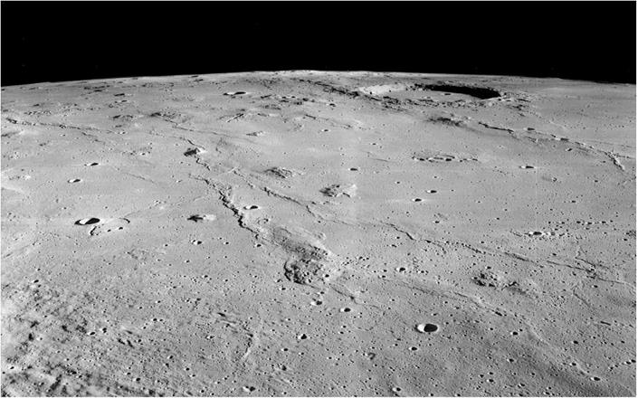
An oblique view taken by Lunar Orbiter 2 on 25 November 1966 showing the hills and flow fronts in western Oceanus Procellarum near the crater Marius.
|
Table 11.2 – Lunar Orbiter 2 orbital manoeuvres and photography
|
fractures. There was concern that if the maria were lava flows, then by terrestrial analogy they might contain lava tubes which could collapse under the weight of an Apollo lander. Lawrence Rowan of the US Geological Survey ventured that in this respect younger-looking mare areas (such as II-P-2) appeared to pose a greater risk than older-looking mare areas (such as II-P-6). It had been possible to fit 23 Apollo target ellipses into clear-looking patches in the Lunar Orbiter pictures to date. After these had been screened by counting small craters and measuring slopes, eight were selected for further study.
On 5 January 1967 the Surveyor/Orbiter Utilisation Committee approved the plan for the third mission. As its predecessors had reconnoitred all the assigned targets, Lunar Orbiter 3 was to provide additional data for those which the screening process had deemed to be the most promising. The spacecraft was identical, but the operational plan was more sophisticated. At the western end of the Apollo zone, launches at different times of year favoured passing either north or south of the equator. In the case of the first mission, the orbit was inclined at 12 degrees to the lunar equator in order to photograph sites lying south of the equator from a vertical perspective, and for the second mission the orbit was inclined the other way for sites north of the equator. To enable Lunar Orbiter 3 to cover the entire latitude range, its orbit was to be inclined at an angle of 21 degrees. It was given 12 primary and 32 secondary targets. It was to obtain H frames of the best-looking areas that had been imaged by Lunar Orbiter 1 as M frames but not by Lunar Orbiter 2 as H frames. In particular, it was to provide pictures to facilitate stereoscopic analysis to compile terrain maps with 3-metre contours, in order to chart the topography on the line of approach from the east over which an Apollo lander would pass during its powered descent to a target.[32] This marked a switch from reconnoitring areas to certifying specific targets. Some of the secondary frames were oblique views of Apollo sites, taken looking west to show them as they would appear to astronauts preparing to make a descent. It was felt that three Lunar Orbiter missions in the equatorial zone should be sufficient to select targets for the first few Apollo landings. The Manned Spacecraft Center also wanted further radio tracking in lunar orbit to investigate anomalous gravitational effects which had been revealed by tracking the first two missions.
Lunar Orbiter 3 was launched at 01:17:01 GMT on 5 February 1967. Translunar injection was at 01:36:56. The spacecraft was released at 01:39:40 and deployed its appendages. Some 7 hours into the flight, it locked onto Canopus to adopt its cruise attitude. At 15:00 on 6 February the spacecraft executed a 4.3-second, 5.1-m/s midcourse manoeuvre to achieve the orbit insertion point for the desired inclination. At 04:20 on 7 February, an optional refinement was deleted. At 21:54:19 on 8 February the spacecraft began the 542-second burn to enter an initial orbit of
|
|
210 x 1,850 km inclined at 21 degrees to the lunar equator with a period of 3 hours 25 minutes. As Lunar Orbiter 2 was still providing selenodesy data, the Deep Space Network tracked both spacecraft to enable the Manned Space Flight Network to obtain experience of simultaneously monitoring two vehicles in lunar orbit, as it would for an Apollo mission.
At 18:13:26 on 12 February, Lunar Orbiter 3 lowered its perilune to 55 km. The photographic mission started on 15 February – the first sequence was of the Apollo target in eastern Tranquillitatis. The phase of the Moon was ‘new’ on 9 February; ‘first quarter’ would occur on 17 February and ‘full’ on 24 February.
When the mechanism that advanced the film started to behave erratically, it was decided to cancel an oblique picture of Grimaldi (III-S-32) in order to start the read out process a day early. Accordingly, at 06:36 GMT on 23 February the spacecraft was told to cut the Bimat strip. But film transport continued to be problematic, and when the motor burned out on 4 March only 182 of the 211 frame-pairs had been transmitted; some of the earliest were lost.3
On 12 April the orbit was revised to minimise the time the spacecraft would spend in darkness during the lunar eclipse of 24 April. On 30 August it made a 125-second burn to circularise its orbit at 160 km, in order to provide experience for the Manned Space Flight Network in tracking a spacecraft in an orbit similar to that which would be used by Apollo. On 9 October 1967 Lunar Orbiter 3 was deliberately crashed on the far-side – two days before its predecessor was commanded to do likewise.
The photographs of III-P-12 were to locate Surveyor 1, and were accumulated in four overlapping blocks on successive revolutions. The lander had oriented its two mast-mounted panels to maximise its shadow and hence improve its visibility on the surface. After it was pin-pointed on an H frame, it was able to be located on one of
|
Table 11.3 – Lunar Orbiter 3 orbital manoeuvres and photography
|
|
Table 11.3 cont.
|
|
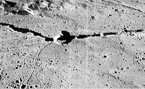
Hyginus Rille by Lunar Orbiter 3. |
|
Table 11.4 – |
Apollo site reconnaissance |
|
|
Mission |
No. sites |
No. exposures |
|
LO-1 |
9 |
136 |
|
LO-2 |
13 |
184 |
|
LO-3 |
18 |
162 |
|
Total |
40 |
482 |
|
Note: Some sites were assigned to more than one mission. |
the M frames taken by Lunar Orbiter 1 – although only in hindsight. The scientific targets included oblique perspectives of the 32-km-diameter crater Kepler (III-S-26) in Oceanus Procellarum and the 11-km-diameter crater Hyginus in Sinus Medii and the associated rille (III-S-6) that was suspected by some people of being of volcanic origin and was under consideration as a site for an advanced Apollo mission.
As soon as the Lunar Orbiter 3 readout ended, the screening team reconvened at Langley to assess the results. Now that the Surveyor 1 site was known, the landscape observed by that vehicle provided the ‘ground truth’ needed to test the validity of the process of interpreting overhead pictures – this was a major part of the rationale for devoting so many frames to seeking the lander.
As a result of the first three Lunar Orbiter missions 32 individual sites clustered in eleven groups in the Apollo zone had been comprehensively photographed. These, and nine less intensively imaged sites, were designated ‘Set A’ for the selection of the early Apollo landings sites.
|
|||
|
|||
|
|||
|
|||
|
|||
|
|||
|
|||
|
|||
|
|
||
|
|||
|
|||
|
|||
![]()
assail
FPACASTORIL
PU P’BsAC I
PEGIOMGN1
■ РІТАТЦЗ.
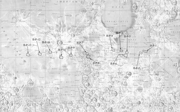
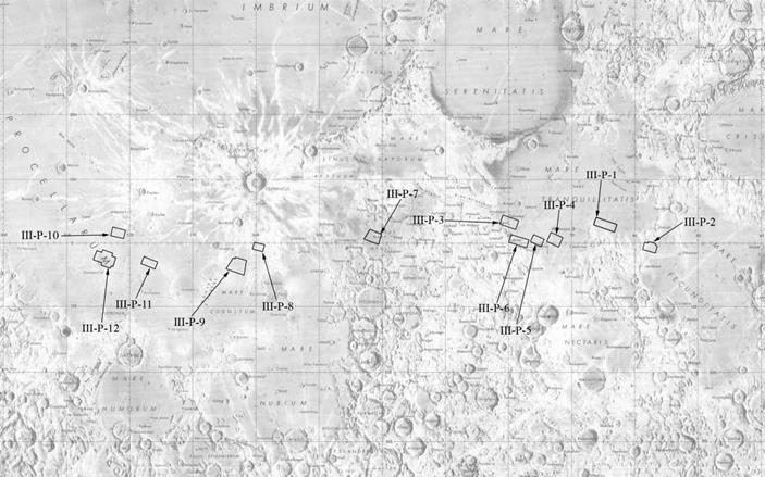
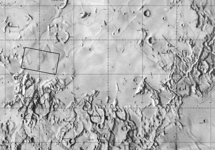
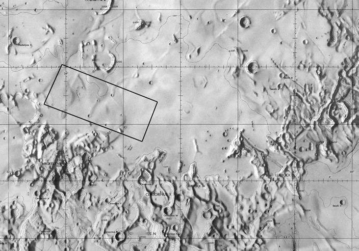
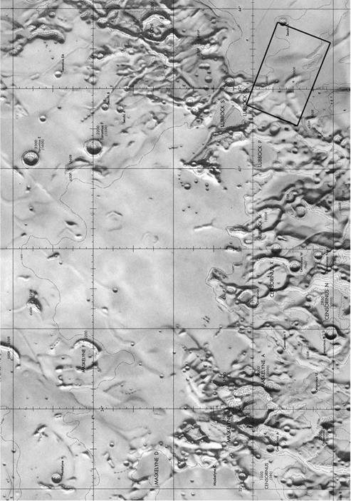
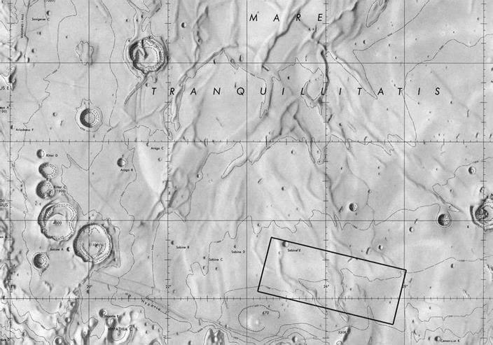
![]() The Apollo zone annotated with the primary photographic targets jointly assigned to the Lunar Orbiter 1, 2 and 3 missions.
The Apollo zone annotated with the primary photographic targets jointly assigned to the Lunar Orbiter 1, 2 and 3 missions.
|
|
|
|
|
|
|
|
|
|
|
|
|
|
|
|
|
|
|
|
|
|
|
|
|
|
|
‘1000 1 CENSORINUS (380) 4 |
|
:ensorinus n 1 |
|
|
|
|
|
|
|
|
|
|
|
|
|
|
|
|
|
|
|
|
|
|
|
|
|
|
|
|
|
|
|
|
|
|
|
|
|
|
|
 |
|
|
|
|
|
|
|
|
|
|
|
|
|
|
|
|
|
|
|
|
|
|
|
|
|
|
|
|
|
|
|
|
|
|
|
‘1000 1 CENSORINUS (380) 4 |
|
|
|
|
|
|
|
|
|
|
|
|
|
|
|
|
|
|
|
|
|
|
|
|
|
|
|
|
 |
242 The Apollo zone
|
|
|
|||
|
|||
|
|||
|
|||
|
|||
|
|||
|
|||
|
|||
|
|||
|
|
||
|
|||
|
|||
|
|
|
|
|
|
|
|
|
|
|
|
|
|
|
|
|
|
|
|
|
|
|
|
|
|
|
|
|
|
|
|
|
|
|
|
|
|
|
|
|
|
|
|
|
|
|
|
|
|
|
|
|
|
|
|
|
|
|
|
|
|
|
|
|
|
|
|
|
|
|
|
|
|
|
|
|
|
|
|
|
|
|
|
|
|
|
|
|
|
|
|
|
|
|
|
|
|
|
|
|
|
|
|
|
|
|
|
|
|
|
|
|
|
|
|
|
|
|
|
|
|
|
|
|
|
|
|
|
|
|
|
|
|
|
|
|
|
|
|
|
|
|
|
|
|
|

|
|
 |
256 The Apollo zone
|
|
|
|||
|
|||
|
|||
|
|||
|
|
||
|
|||
|
|||
|
|||
|
|
||
|
|||
|
|||
|
|||
|
|||
|
|||
|
|
|
• ‘ I4 шш |
|
|||
|
|||
|
|||
|
|||
|
|
||
|
|||
|
|||
|
|||
|
|||
|
|||
|
|||
|
|||
|
|||
|
|
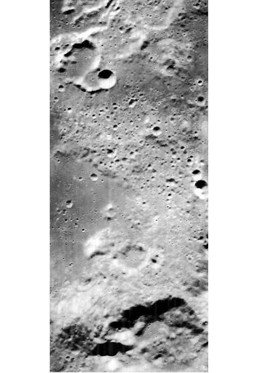
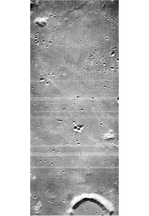
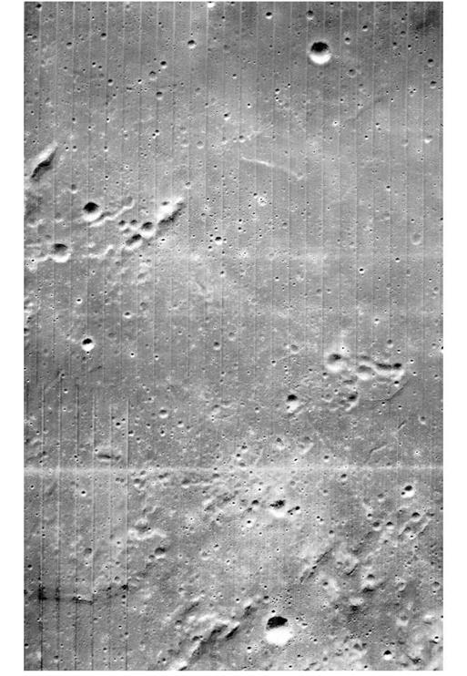
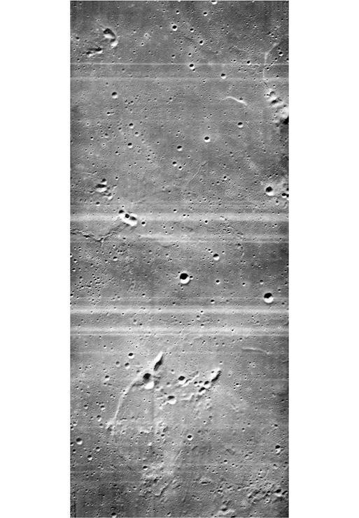
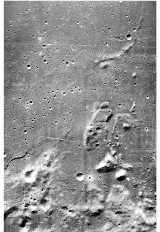
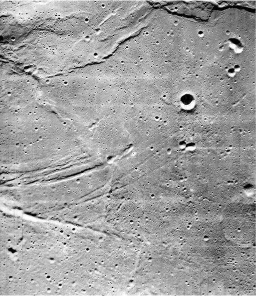
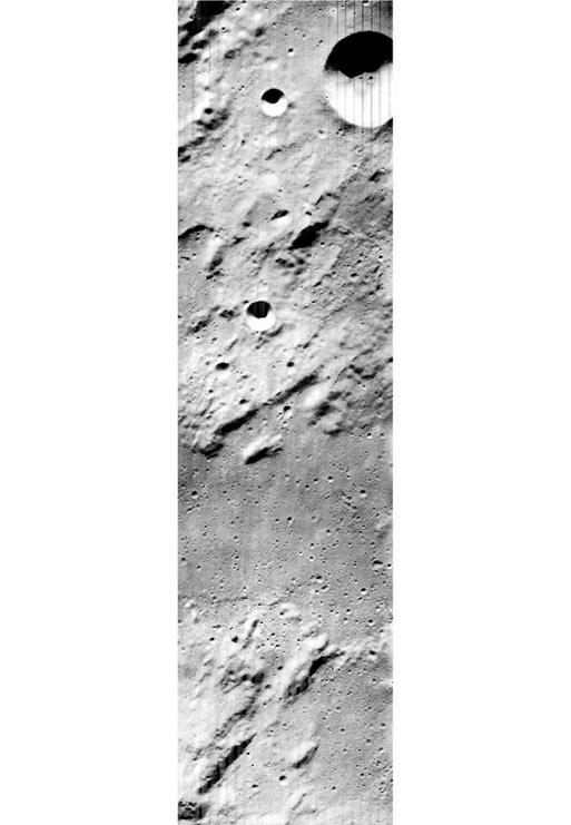
Lunar Orbiter photographic target II-P-8. |
|
37004- 7AMBAR1 (1090) |
|
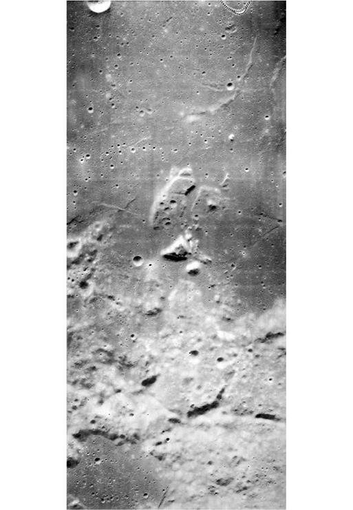
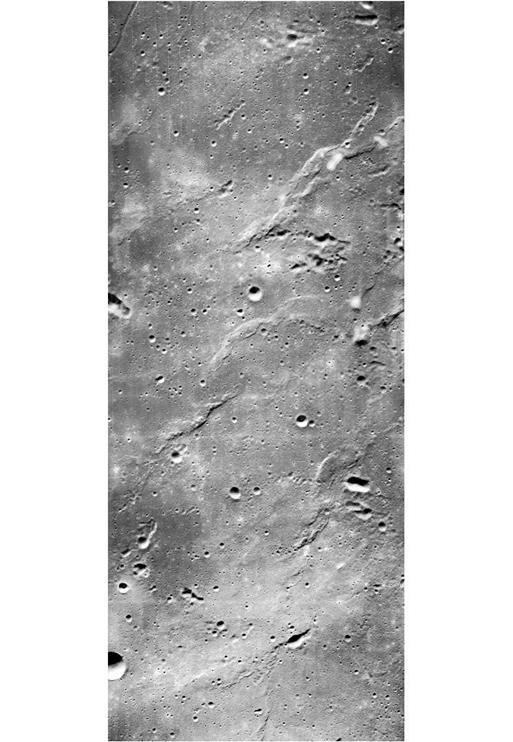
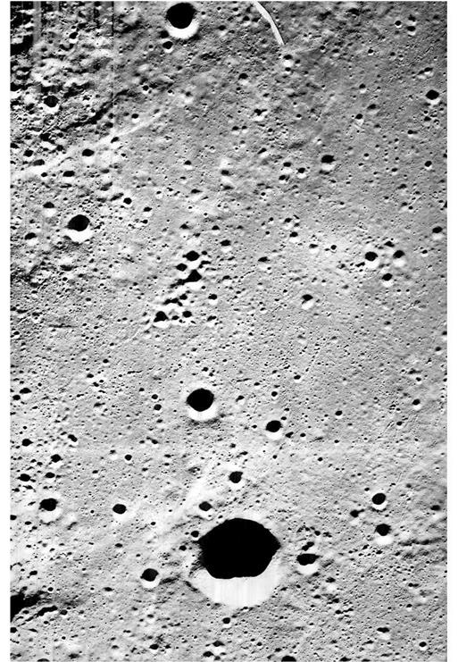
Lunar Orbiter photographic target I-P-7. |
|
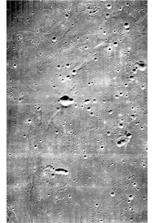
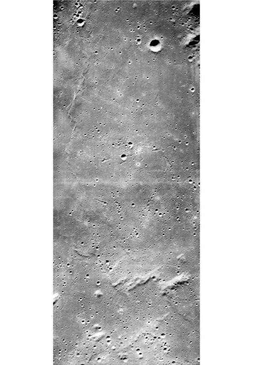
Lunar Orbiter photographic target II-P-11. |
|
І uWl |
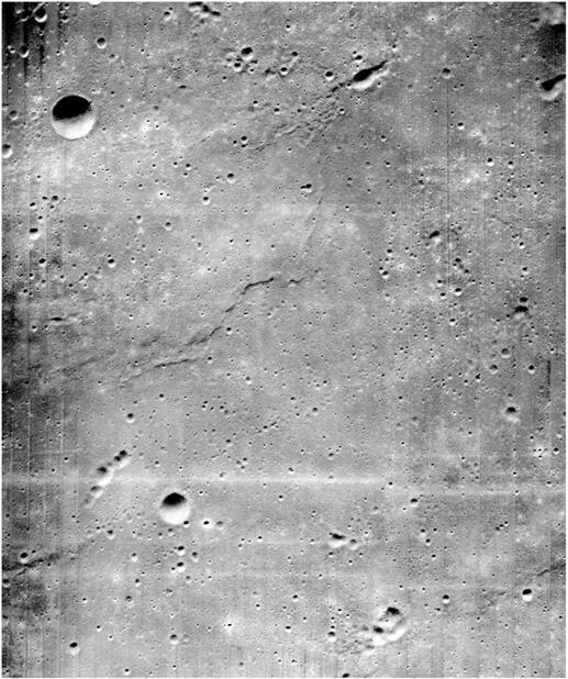
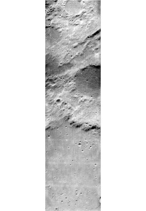
By design, the ellipses selected as potential targets for the first Apollo landing were bland areas.
Apollo site short-list 285


