RANGERS FOR APOLLO
When on 25 May 1961 President Kennedy challenged his nation to land a man on the Moon before the decade was out, the sky scientists were unimpressed but the geologists were delighted.
On 8 June Hugh Dryden advised the Senate Committee on Aeronautics and Space Sciences that NASA intended to make use of automated spacecraft to strengthen the manned lunar program. In particular, it was essential to find out whether the surface would support the weight of the Apollo lander. As Dryden put it, ‘‘We want to know something about the character of the surface on which the landing is to be made, and obtain as much information as we can before man actually gets there.’’ Following up, Abe Silverstein provided some details. For a start, Ranger would be extended by four Block III missions. Congress authorised the funding for these missions several weeks later.
Clifford Cummings, JPL’s Lunar Program Director, visited NASA on 21 June and told Edgar Cortright and Oran Nicks, the two managers in Silverstein’s office who were responsible for Ranger, that the greatest single contribution this project could make to Apollo would be to provide high-resolution imagery to enable the nature of the lunar surface to be characterised to provide the information needed to design the landing gear of the Apollo lander. For this, the Block III would replace the surface package subassembly with a TV system that was more sophisticated than that made for the Block II. In the interim, some insight would be provided by the Block II radar altimeter and the accelerometers of the surface capsule as this impacted and rolled to a halt.
JPL recommended that the contract to develop the high-resolution TV system go to the same company that supplied the camera for the Block II, and this was agreed.
|
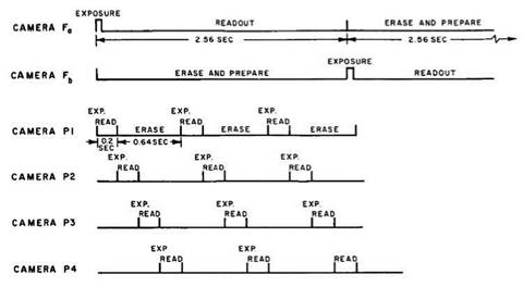
The shuttering sequence of the six cameras of the Block III Ranger spacecraft’s high – resolution TV system. |
On 5 July 1961 JPL discussed the design of the system with the Radio Corporation of America, and it was decided to use a shutter (which was not a standard feature on a continuous-scan TV system) to define a ‘frame’ on a vidicon tube. The contract was signed on 25 August. Responsibility for the design, fabrication and testing of the system was delegated to the company. Harris Schurmeier’s Systems Division would monitor the work. On 31 August, Cummings appointed Allen E. Wolfe as the Ranger Spacecraft Systems Manager to assist James Burke with the increased work. Wolfe had replaced Gordon Kautz as Project Engineer in the Systems Division when Kautz was made Burke’s deputy. Wolfe’s first responsibility would be to steer the remaining Block II spacecraft through all phases of assembly and testing, and then supervise the development of the Block III.
The design of the high-resolution TV subsystem was finished in September 1961. It had three major assemblies: a tower superstructure incorporating a thermal shield to stand on the top of the hexagonal bus; a central box to house the main electronics; and, above, a battery of six cameras and their individual electronic systems. It used two types of camera. The ‘A’ type had a lens with an aperture ratio of f/1 and a focal length of 25 mm. The ‘B’ type had an f/2 lens with a focal length of 75 mm. There were two ‘A’ cameras and four ‘B’ cameras. The vidicons were all the same, but the entire 11-mm square image would be used for the full (F) frame and only the central 3-mm square for the partial (P) frame. One ‘A’ and one ‘B’ camera would operate a 5.12-second cycle in which the shutter fired to expose its vidicon and this was read out over an interval of 2.56 seconds, then erased over the next 2.56 seconds. They were to operate out of phase so that a frame was taken every 2.56 seconds. The other cameras would require 0.2 second to fire the shutter and perform the readout, and 0.6 second to erase. The faster cycle time for these cameras was because a smaller
area was to be scanned. They were to be cycled to take a frame every 0.2 second, in the hope that one camera would be able to provide a close-up picture just prior to impact. The cameras were mounted at angles designed to provide overlap to enable the relationship of one frame to be related to those preceding and following. The TV subsystem would have its own battery, independent of the bus, and a pair of 60-watt transmitters. Unlike the Block II, whose flow of pictures would conclude when the separation of the surface package caused the high-gain antenna to lose its lock on Earth, the Block III would continue to send pictures until it hit the surface. In all, the high-resolution TV subsystem would be 160 kg.6
As in the case of the Block I, the low-gain antenna would be in a fixed position at the top of the tower. The designers of the Block III had the luxury of being able to exploit the full payload capacity of the Atlas-Agena B, and this allowed some degree of redundancy in the basic systems.
On 19 September 1961 NASA announced that the Block IIIs were to be launched in January, April, May and August 1963 – certainly they were to be over before the first soft-landing Surveyor, which was expected in 1964.


