Modern Rotor Aerodynamic Limits Survey
The Modern Rotor Aerodynamic Limits Survey was a 10-year program launched in 1984, which encompassed flight efforts in 1987 and 1993— 1994. In 1987, a Sikorsky UH-60A Black Hawk was tested with conventional structural instrumentation installed on the rotor blades. Then:
. . . Sikorsky Aircraft was [subsequently] contracted to build a set of highly instrumented blades for the Black Hawk test aircraft: a pressure blade with 242 absolute pressure transducers and a strain-gauge blade with an extensive suite of strain gauges and accelerometers. . . approximately 30 gigabytes of data were obtained in 1993-94 and installed in an electronic database that was immediately accessible to the domestic rotorcraft industry.[948]
![]()
 Comparison Ground Test Data
to NASTRAN
: niches
OO WO 140 -«О WO 200 220
WING SPAN (cm)
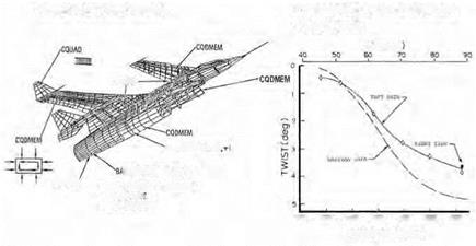
NASTRAN model and NASTRAN to static test comparison. NASA.
The two types of measurement systems are complementary. Strain gauges give an indication of the total load in a member, but little insight to the details of where and how the load is generated. The pressure taps show the distribution of the applied aerodynamic load, but only at given stations, so the total load estimate depends on how one computes the data through the unknown regions between the pressure transducers. The combination of both types of data is most useful to researchers trying to correlate computational loads predictions with the test data.
HiMAT
HiMAT was a small, unpiloted aircraft (23.5-feet long, 15.6-foot wingspan, weight just over 3,000 pounds) somewhat representative of a fighter type configuration, flown between 1979 and 1983, and developed to evaluate the following set of technologies and features:
• Close-coupled canard.
• Winglets.
• Digital fly-by-wire flight control.
• Composite structure.
• Aeroelastic tailoring.
• Supercritical airfoil.
It was intended that the benefits of these collected advances be shown together rather than separately and on an unpiloted platform, so that
![]()
 НІМАТ Wing with Electro-Optical Deflection Measurement System
О Targets
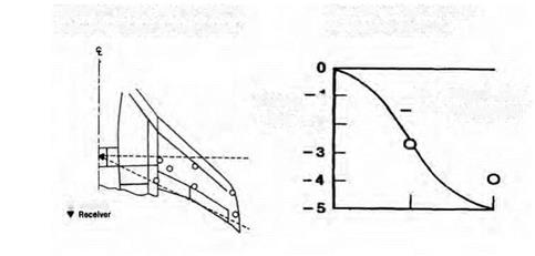
HiMAT Electro-Optical Flight Deflection Measurement System. NASA.
the vehicle could be tested more aggressively without danger to a pilot.[949]
"Aeroelastic tailoring” refers to the design of a structure to achieve aerodynamically favorable deformation under load, rather than the more traditional approach of simply minimizing deformation. The goal of aeroelastic tailoring on the HiMAT ". . . was to achieve an aero-dynamically favorable spanwise twist distribution for maneuvering flight conditions” in the canard and the outboard wing. "The NASTRAN program was used to compute structural deflections at each model grid point. Verification of these deflections was accomplished by performing a loads test prior to delivery of the vehicle to NASA.” The ground-test loads were based on a sustained 8-g turn at Mach 0.9, which was one of the key performance design points of the aircraft. The NASTRAN model and a comparison between predicted and measured deflections are shown in the accompanying figure. Canard and wing twist were less than predicted. The difference was attributed to insufficient understanding of the matrix-dominated laminate material properties.[950]
The vehicle was also equipped with a system to measure deflections of the wing surface in flight. Light emitting diodes (LEDs)—referred to as targets—on the wing upper surface were detected by a photodiode
array mounted on the fuselage, at a location overlooking the wing. Three inboard targets were used to determine a reference plane, from which the deflection of the remaining targets could be measured. To measure wing twist, targets were positioned primarily in pairs along the front and rear wing spars.[951] The HiMAT wing had a relatively small number of targets—only two pairs besides the inboard reference set—so the in-flight measurements were not a detailed survey of the wing by any means. Rather, they provided measurement at a few key points, which could then be compared with the NASTRAN data and the ground loads test data. Target and receiver locations are illustrated here, together with a sample of the deflection data at the 8-g maneuver condition. In-flight deflection data showed similar twist to the ground-test data, indicating that the aerodynamic loads were well predicted.[952]
The HiMAT was an early step in the development of aeroelastic tailoring capability, providing a set of NASTRAN data, static load test data, and flight-test data, for surface deflection at a given loading condition. The project also proved out the electro-optical system for in-flight deflection measurements, which would later be used in the X-29 project.


