Induced Structural Resonances
Overall, electronic enhancements introduced significant challenges with respect to their practical incorporation in an airplane. Model-following systems required highly responsive servos and high gain levels for the feedback from the motion sensors (gyros and accelerometers) to the control surfaces. These high-feedback-gain requirements introduced serious issues regarding the aircraft structure. An aircraft structure is surprisingly vulnerable to induced frequencies, which, like a struck musical tuning fork, can result in resonant motions that may reach the naturally
|
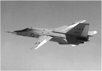
The General Dynamics F-111A was the first production aircraft to use a self-adaptive flight control system. NASA. |
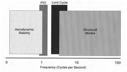
destructive frequency of the structure, breaking it apart. Rapid movement of a control surface could trigger a lightly damped oscillation of one of the structural modes of the airplane (first mode tail bending, for example). This structural oscillation could be detected by the flight control system sensors, resulting in further rapid movement of the control surface. The resulting structural/control surface oscillation could thus be sustained, or even amplified. These additive vibrations were typically at higher frequencies (5-30 Hz) than the limit-cycle described earlier (2-4 Hz), although some of the landing gear modes and wing bending modes for larger aircraft are typically below 5 Hz. If seemingly esoteric, this phenomenon, called structural resonance, is profoundly serious.
Even the stiff and dense X-15 encountered serious structural resonance effects. Ground tests had uncovered a potential resonance between the pitch control system and a landing gear structural mode. Initially, researchers concluded that the effect was related to the ground-test equipment and its setup, and thus would not occur in flight. However, after several successful landings, the X-15 did experience a high-frequency vibration upon one touchdown. Additionally, a second and more severe structural resonance occurred at 13 Hz (coincident with the horizontal tail bending mode) during one entry from high altitude by the third
X-15 outfitted with the MH-96 adaptive flight control system.[693] The pilot would first note a rumbling vibration that swiftly became louder. As the structure resonated, the vibrations were transmitted to the gyros in the flight control system, which attempted to "correct” for them but actually fed them instead. They were so severe that the pilot could not read the cockpit instruments and had to disengage the pitch damper in order to stop them. As a consequence, a 13 Hz "notch” filter was installed in the electrical feedback path to reduce the gain at the observed structural frequency. Thereafter, the third X-15 flew far more predictably[694]
Structural resonance problems are further complicated by the fact that the predicted structural frequencies are often in error, thus the flight control designers cannot accurately anticipate the proper filters for the sensors. Further, structural resonance is related to a structural feedback path, not an aerodynamic one as described for limit-cycles. As a precaution, ground vibration tests (GVT) are usually conducted on a new airplane to accurately determine the actual structural mode frequencies of the airplane.[695] Researchers attach electrically driven and controlled actuators to various locations on the airplane and perform a small amplitude frequency "sweep” of the structure, essentially a "shake test.” Accelerometers at strategic locations on the airplane detect and record the structural response. Though this results in a more accurate determination of the actual structural frequencies for the control system designer, it still does not identify the structural path to the control system sensors.
The flight control resonance characteristics can be duplicated on the ground by placing the airplane on a soft mounting structure, (airbags, or deflated tires and struts) then artificially raising the electrical gain in each flight control closed loop until a vibration is observed. Based on its experience with ground – and flight-testing of research airplanes, NASA DFRC established a ground rule that the flight gains could only be allowed to reach one-half of the gain that triggered a resonance (a gain margin of
2.0). This rule-of-thumb ground rule has been generally accepted within the aircraft industry, and ground tests to establish resonance gain margins are performed prior to first flights. If insufficient gain margin is present, the solution is sometimes a relocation of a sensor, or a stiffening of the sensor mounting structure. For most cases, the solution is the placement of an electronic notch filter within the control loop to reduce the system gain at the identified structural frequency. Many times the followup ground test identifies a second resonant frequency for a different structural mode that was masked during the first test. A typical notch filter will lower the gain at the selected notch frequency as desired but will also introduce additional lag at nearby frequencies. The additional lag will result in a lowering of the limit-cycle boundaries. The control system designer is thus faced with the task of reducing the gain at one structural frequency while minimizing any increase in the lag characteristics at the limit-cycle frequency (typically 2-4 Hz). This challenge resulted in the creation of lead-lag filters to minimize the additional lag in the system when notch filters were required to avoid structural resonance.[696]
Fighter aircraft usually are designed for 7-9 g load factors and, as a consequence, their structures are quite stiff, exhibiting high natural frequencies. Larger transport and reconnaissance airplanes are designed for much lower load factors, and the structures are more limber. Since structural frequencies are often only slightly above the natural aerodynamic frequencies—as well as the limit-cycle frequencies—of the airplane, this poses a challenge for the flight control system designer who is trying to aggressively control the aerodynamic characteristics, avoid limit-cycles, and avoid any control system response at the structural mode frequencies.
Structural mode interactions can occur across a range of flight activities. For example, Rockwell and Air Force testers detected a resonant vibration of the horizontal stabilizer during early taxi tests of the B-1 bomber. It was traced to a landing gear structural mode, and a notch filter was installed to reduce the flight control gain at that frequency. The ground test for resonance is fairly simple, but the structural modes that need to be tested can produce a fairly large matrix of test conditions. External stores and fuel loadings can alter the structural frequencies of the airplane and thus change the control system feedback
|
Aircraft frequency spectrum for flight control system design. USAF. |
characteristics.[697] The frequency of the wing torsion mode of the General Dynamics YF-16 Lightweight Fighter (the prototype of the F-16A Fighting Falcon) was dramatically altered when AIM-9 Sidewinder air-to-air missiles were mounted at the wingtip.
The transformed dynamics of the installed missiles induced a serious aileron/wing-twist vibration at 6 Hz (coincident with the wing torsion mode), a motion that could also be classified as flutter, but in this case was obviously driven by the flight control system. Again, the solution was the installation of a notch filter to reduce the aileron response at 6 Hz.[698]
NASA researchers at the Dryden Flight Research Center had an unpleasant encounter with structural mode resonance during the Northrop-NASA HL-10 lifting body flight-test program. After an aborted launch attempt on the HL-10 lifting body, the NB-52B mother ship was returning with the HL-10 still mounted under the wing pylon. When the HL-10 pilot initiated propellant jettison, the launch airplane immediately experienced a violent vibration of the launch pylon attaching the lifting body to the NB-52B. The pilot stopped jettisoning and turned the flight control system off, whereupon the vibration stopped. The solution to this problem was strictly a change in operational procedure—in
the future, the control system was to be disengaged before jettisoning while in captive flight.[699]


