PRODUCT-ORIENTED ENGINEERING EXCHANGE
The Boeing-Douglas-Vega (BDV) pool was among the first of the major wartime aircraft cooperatives. As a product-oriented organization it illustrates the manner in which engineering knowledge is embedded within a firm. Before the attack on Pearl Harbor, the US government made arrangements for a number of standard aircraft types to be produced jointly by different manufacturers. Boeing, Douglas and Vega were to produce the B-17 bomber, a four-engine Boeing design begun in 1934. Implicit in such an arrangement was that Douglas and Vega would gain access to Boeing’s system of manufacture. Within this system Boeing had many individual production techniques unique to their company, some proprietary, others matters of Boeing’s manufacturing culture. Among the differences noted in the trade journals were Boeing’s drawing system, factory methods, and unique tools.18 To coordinate the three companies’ manufacturing, procurement, design changes, and scheduling issues, they formed the BDV Committee. Begun in May of 1941, the Committee was located in Seattle and included representatives from all three manufacturers as well as the Army Air Corps (later the Army Air Forces after its 1942 reorganization). In addition to a powerful executive committee, three subcommittees operated, including Tooling, Technical, and Procurement, all based in Seattle. Through these committees, Douglas and Vega were given “ready access to all phases of Boeing production.”19
The BDV Committee contemplated a wide-ranging transfer of information, extending beyond aircraft blueprints to include production information as well. Douglas and Vega received all the master tooling and jigs, as well as one complete aircraft and numerous sets of parts for initial production. From their factories in southern California, Douglas and Vega sent scores of workers to Boeing’s Seattle facilities to personally observe tooling construction and manufacturing methods. The extent of cooperation was so great that workers from all three companies joined in building assembly and sub-assembly jigs. Highlighting the relationship between production and organization, an integral part of the technology transfer to Douglas and Vega was managerial information, including major assembly man-hour lists, percentage breakdown charts, schematic drawings with man-hour indications, assembly books, parts cards, and parts list. These were all means for controlling and auditing production flow. Finally, Boeing learned to adopt some of the methods it found in Southern California, such as Douglas’ “production illustration” method.20
The members of the BDV Committee were not entirely unprepared for the obstacles posed by technology transfer. Indeed, they seemed quite aware of the fact that traditions differed dramatically between firms. Regarding tooling, Mac Short, the Vega Vice President of Engineering wrote:
A survey of existing tooling by the Tooling Subcommittee revealed that there was in existence in the Boeing plant a number of small tools for which there were no available drawings. These tools had been constructed in many cases by the workmen on the job during the preceding years of building B-17s. It was the decision of the BDV Committee that these tools represented “knowhow” and would be of aid to the Douglas and Vega companies if the information could be transferred to them.
The exchange of such “know-how” was a necessary component of bridging these different engineering cultures. Indeed, the BDV Committee had to create a standard nomenclature for design and tooling engineers since all three companies had, essentially, different languages.21
Still, there was great confidence that the three manufacturers would be able to build identical aircraft. Boeing’s own press releases boasted that “[Boeing, Douglas and Vega] will turn out completely assembled four-engine bombers, identical even to the point of interchangeability of parts.”22 What members of the BDV Committee did not anticipate was the extent to which differing traditions of manufacture as well as conflicting production philosophies would preclude the complete adoption of Boeing’s production system. So long as differences remained, there were bound to be discrepancies between the aircraft produced.
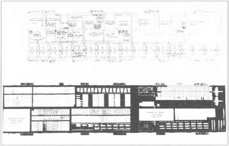
Boeing used what it called a production-density system (later termed multi-line). The process brought nearly complete assemblies together at the very last stage of manufacture.23 Rather than a dominant single assembly line stretching from jigs to the hangar doors, each assembly had its own line terminating at final assembly (figure 3). Most of the installation work on the assemblies was completed before final assembly, meaning that aircraft spent the least amount of time in the stage that consumed the most space. Production-density was considered, “the antithesis of the elongated single production line.”24 The logic behind concentrating on assemblies and sub-assemblies as opposed to final assembly was ably described by Sidney Swirsky, writing with a touch of vitriol in 1943:
That the ideal straight-assembly line for aircraft is, after the fashion of the auto-makers, the final assembly line, is in itself strictly mythical. Actually, the aviation production line must start when parts are received in the form of raw stock at one end of the plant. In order to get more sub-assemblies to the final line faster, the plant’s board of strategy, including the vice president of manufacturing, the factory manager and the plant layout engineer, must straighten out as much as possible the lines by which fabricated parts and sub-assemblies are to reach the final line. The final
|
Figure 3. Boeing B-17 Major and Final Assembly (Plant 2 in Seattle). Fuselage and wing assemblies moved by overhead bridge crane from pick-up fixtures to very short final assembly lines, redrawn by Louise Liu from US Army Air Force, Industrial Planning Section, Air Materiel Command, “Boeing Aircraft Company, Seattle, Washington, B-17 Production and Construction Analysis,” 29 May 1946, exhibit 21, Boeing Archives. |
line itself in an aircraft plant is much less a problem than are the sub-assembly lines; the complexity of routing and fabricating airplane sub-assemblies is the cause of the ever-threatening bottleneck which can stop production – not straightness or lack of it in the final line, [his italics]25
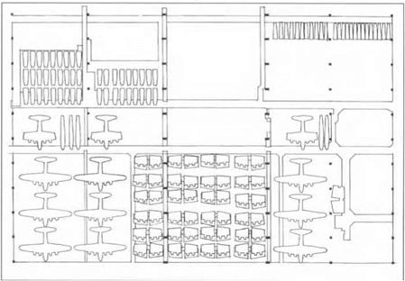
For Boeing, eliminating the long final assembly line and opting for numerous lines of shorter length had the advantage of requiring less expansive production facilities – one of the original reasons for its adoption in the late 1930s. But as prime contractors for production, not subcontractors, Douglas and Vega were not obligated to implement Boeing’s production-density system. There is no doubt that they benefited from Boeing’s experience, but they were forced to blend Boeing’s aircraft into their own companies’ manufacturing culture. Engineers at Douglas decided that straight-line final assembly was just the thing (Figure 4). Cradled by overhead carriers, workers mated fuselage sections which progressed from station to station down the line. At the first station of final assembly, the fuselage was already in one piece while workers attached the wing sections. Installation of parts and components continued through final assembly. Douglas would later call its straight-line assembly system “Flow-line” and apply it to the A-20 and A-26 aircraft lines. Vega opted for a third system, which it vaguely described as a
“breakdown system.” The focus here was on the fabrication of numerous small preassembled components that came together on master jigs. Vega, not unlike the other manufacturers, explained that its system attempted to make the best use of very limited floorspace.26
 The result was three different ways of producing the B-17, and an indeterminacy about the best way to mass produce aircraft. An engineer writing on the Douglas system was careful to avoid making comparisons between different production ideologies, arguing that, “Among the many abilities of Americans… is the ingenuity by which different groups achieve similar or identical results, but with widely varying, sometimes seemingly opposite methods.” Unfortunately, the resulting aircraft from these methods were merely similar, and never identical. In fact, in October of 1943 General “Hap” Arnold specifically contacted the National Aircraft War Production Council (NAWPC) about the “non-interchangeability” of assemblies from different companies. He complained that “the different processes employed by the various manufacturers preclude the replacement of a Vega tail assembly by a Boeing or a Douglas tail assembly.” Despite rigid adherence to a single set of master gages and templates supplied by Boeing, differing production ideologies and traditions of practice brought about three different products.27
Figure 4. Douglas B-17 Major and Final Assembly (Building 12 and 13 of the Long Beach Plant). The assemblies and sub-assemblies move from left to right in the bottom building, and then from right to left in the upper building. Source: US Army Air Force, Air Materiel Command, Industrial Planning Branch, “Construction and Production Analysis: Douglas – Long Beach, B-17” (August 1946), exhibits 8 and 9.
While writers lauded the identical qualities of the aircraft in public, the manufacturers privately expressed their concerns about interchangeability within the Aircraft War Production Council. Even companies that were not part of the larger co-production schemes had great difficulty maintaining interchangeability. They attributed the problem to a number of causes, including sub-contractors who, despite having master jigs, often produced parts differently. Within the main airframe firms, they noted the following:
Here a distinct difference in manufacturing processes, tooling, model design, equipment and some small parts exists. The introduction of changes varies. The character of tooling is as diverse as the date, volume, and production rate of each contract, the plant lay-out, type and skill of personnel, climatic conditions, local fabricating habits, and material substitutions and improvisations.
The problems outlined by Hap Arnold were eventually addressed in military specification AN-I-21, which called for various classes of interchangeability. But while the military wanted interchangeable assemblies, sub-assemblies, and parts, such requirements would entail that engineering cultures attain some level of interchangeability as well. Ultimately the Aircraft War Production Council informed the government that the AN-I-21 specification would be impossible to implement across the industry. They argued that because “each company and product presents a specific design and manufacturing problem,” that solutions would need to be equally individualized.28
Despite the lessons of the BDV experience, technology transfer and interchangeability issues remained, even for subsequent cooperative efforts such as the B-29 pool. The Army had chosen the Boeing B-17 and Consolidated B-24 to be the standard large bomber types for the war, but they also sought to place a more modem and capable aircraft into production. This was the Boeing B-29. Like many other aircraft, it would be produced by a group of manufacturers, including Boeing – Wichita, General Motor’s Fisher Division, and North American Aviation. Eventually GM and North American were replaced by Bell (Marietta, Georgia) and Boeing-Renton, with the Fisher Division remaining as a subcontractor. In time, the Omaha plant of the Glenn L. Martin Company would also join the pool. As with the B-17 pool, there was a B-29 Committee established to handle the same coordination problems that arose on the earlier aircraft. Specific details from the B-29 pool give us additional evidence in understanding the difficulties of engineering exchange.
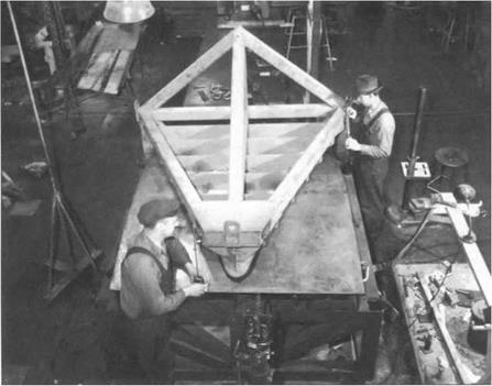
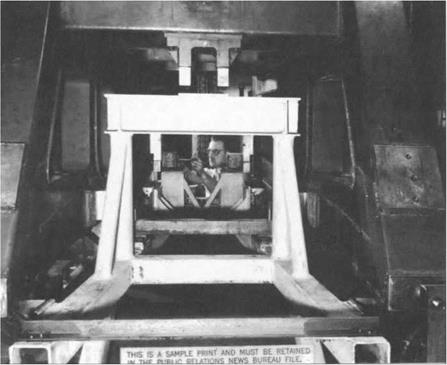
Engineering drawings, when properly rendered, are supposed to communicate all the essential aspects of a design, such that trained workers with appropriate tools can recreate the artifact to specification.29 While Boeing did supply thousands of drawings to the other contractors, all participants understood that these were insufficient to achieve complete interchangeability. Just as a skilled craftsperson uses the same measuring tape for a single project, so did Boeing. The company built master control gages in Seattle which served as the final word on all critical dimensions. These gages remained in Seattle, and were used not to construct aircraft, but to produce other master gages, which in turn would be used to check the accuracy of jigs and completed parts (see figures 5 and 6). Usually the gages bore only slight resemblance, if any, to the assemblies or sub-assemblies to which they corresponded.
Made of thick pieces of steel, the gages were extremely rigid; they conformed to actual aircraft parts at specific reference points – typically locations where a part or assembly would meet another. The B-29 Committee directed the following:
Master gages and master templates shall be used by all four prime contractors and their subcontractors to insure interchangeability of all parts which the Air Corps requires to be interchangeable…. Tooling for fabrication of parts shall be such as to insure that all parts are structurally and aerodynamically identical. It is not contemplated that tooling be identical. Such prime contractor and subcontractor may construct parts by the method or methods best suited to his shop equipment and practices, consistent with the above; however, the Committee must be assured by the contractor concerned that such tooling will produce satisfactory parts.
In theory, exact master gages distributed to all the manufacturers should have rendered the same parts, sub-assemblies, and assemblies.30
Two situations show the difficulty of using master gages as a way to communicate engineering information. In November of 1942, the B-29 Committee wrote: “Trial indicated that the extremely close angular tolerance required could not be successfully transferred from the Boeing furnished Master Gages.” While the
|
Figure 5. B-29 nacelle fairing master gage is checked against the master control gage. Notice the instrument in the foreground, a collimator (modified surveyor’s transit) as well as the workman’s gage employed on the left to measure critical points on the master gage. Boeing Archives, #X-124. |
|
Figure 6. B-29 inboard nacelle assembly jig (light metal) is checked against the master gage (dark metal) for proper location of drill holes. The heavy construction of the master gage is meant to prevent loss of dimensional integrity. Boeing Archives, #X-122. |
information about angular tolerances was encoded into the gage, it could not be used to ensure precision in the produced parts. In effect, the engineering information could not be extracted from the gage without the production of additional gages. A more interesting situation developed a year later when the Committee learned of discrepancies between the nacelles produced by GM’s Fisher plant, and the aircraft wings to which they were attached. The nacelles, when placed on aircraft from the Boeing-Renton facility, had attachment holes that were as far as ft a hole diameter off (a very large distance in a precision product). Boeing-Renton checked its own master control gages and found that their own parts were correct, but that the Fischer parts were not. Bell in Marietta experienced the same problems, but oddly, Boeing’s main B-29 plant in Wichita did not. They fit perfectly there and the plant had already turned out nearly 50 aircraft. The conclusion of the Committee was that,
.. .whether Fisher and Wichita are right or wrong in contrast to Boeing-Renton and Bell, it appears that the only practical answer is for Boeing-Renton and Bell to change their hole locations to coincide with the nacelles as produced by Fisher. This of course will mean the changing of the master gages at Boeing-Renton and Bell and the changing of the master control gage at Boeing-Seattle to agree with the masters at Wichita and Fisher.
Later, Fisher changed the process after the 210th set of nacelles – such that the discrepancies were removed. Why these particular nacelles fit at Boeing – Wichita was not explained, but it begs a question. If two of the most prominent engineering organizations of the 1940s, the Fisher Division of General Motors and the Boeing Company, could not transfer engineering information via accepted methods (drawings and master gages), what engineering organizations in the US were competent to produce and interpret such materials? Obviously the engineering precision that is supposedly built-in to engineering drawings and master gages must be complemented by not only technical skill, but additional forms of communication as well in order to bridge different engineering cultures. This explains, in part, Bell’s insistence that they be furnished a large quantity of parts so as to hand-assemble their first five aircraft. In addition, they asked for “two fuselages in sections, structure only… one fuselage in detail parts,” and finally a “sample airplane complete with installations.” All of these structures served to educate engineers and workers in a way that drawings and gages could not.31
Where gages were not used, drawings were supposed to suffice. One last incident concerning the B-29 gives us additional insight into the process of technological design. In August of 1942 the Fisher Division complained that it had yet to receive the drawings for the electrical wiring. Boeing responded, saying that such drawings were not produced in final form until after the first few aircraft were built. Boeing suggested that someone be sent from the Boeing Electrical Shop to personally advise Fisher, the implication being that this aspect of aircraft design routinely took place closer to the factory floor. Unlike the aforementioned cases where design and tooling information was somehow lost or changed in the transfer process, here we find that design information accrued as the product took shape. This is not surprising, but it suggests further that design trajectories are not fully determined on the engineer’s drafting table. Technicians, mechanics, and laborers not only misinterpret or lose initial design information, they create it as well.32


