Testing the Fan
The fan by itself – i. e., without the turbine blade portion of the bluckets (see Figure 10) – went on test for the first time in September 1957 amid widespread doubts within GE that it would achieve its calculated performance. As Table 1 indicates, it better than merely achieved it. The calculated design point had a pressure-ratio of 1.62 with an adiabatic efficiency of 83 percent at a flow rate of 250 lbs/sec. The measured values were a pressure-ratio of 1.655 and an adiabatic efficiency of 87.2 percent at a flow rate of 257 lbs/sec. Moreover, the off-design performance was excellent – e. g., the highest measured efficiency of 89 percent was at 80 percent speed – and performance was not unduly sensitive to radial and circumferential flow
|
Table 1. GE’s CJ805-23 Fan Aerodynamic Performance
|
distortions of the sort that would occur during flight. Finally, because “the possibility of adaptation of the aft-fan engine to commercial use was considered fairly early in this program,”66 noise measurements were made to assess how much fan “whine” would offset the gain in total engine noise from reducing the exhaust velocity; the results were not discouraging.
|
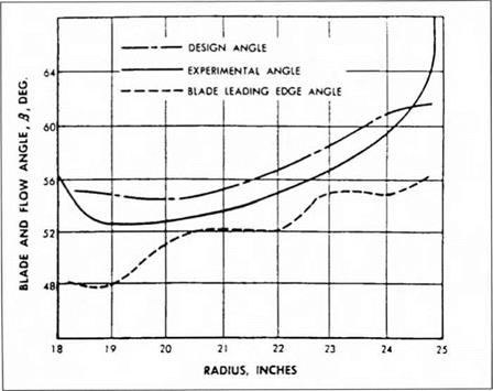
Figure 12. Fan blade leading edge flow angles in General Electric CJ805-23 fan engine, [p. ll.] |
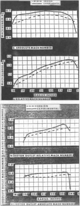
Figure 13. Rotor relative and absolute inlet Mach number in CJ805-23 fan. Note absolute Mach numbers are well below 1, but Mach number relative to rotor is above 1 everywhere but at the inner radius, making this a transonic stage. [p. 12.]
 Figure 14. Rotor relative and absolute outlet Mach number versus radius in CJ805-23 fan. Both relative and absolute outlet Mach numbers are below 1.
[p. 12.]
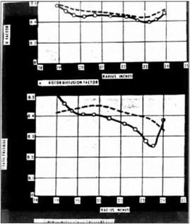
An obvious question is whether the performance was achieved through the analytical method’s successful prediction of the actual detailed flow. The answer is yes and no. In general, the actual blade-element performance did not depart radically from prediction. Only the tip showed a large departure from prediction, most likely because tip-clearance vorticity effects unloaded it. Nevertheless, there were clear discrepancies between prediction and measurement. Figure 12 shows that the rotor leading edge flow angles were around 2 degrees off calculation, probably due to the leading edge configuration that had been dictated by mechanical considerations. Similar discrepancies were found in other parameters. Figures 13 and 14, for example, show the predicted and measured radial variation of the rotor inlet and outlet Mach numbers, respectively, at design speed. The measured blade loadings, specified in terms of the diffusion factor and the static pressure-rise coefficient, are compared with the design values in Figure 15. The actual loadings were generally a little lower than the design values, though the comparatively close agreement in the case of the diffusion factor should be noted. Correspondingly, the actual inlet Mach numbers were around 0.05 higher than predicted over much of the blade. In short, the analytical method did not predict the actual flow to high accuracy. Yet it did provide sufficient control for design purposes.
The aerodynamic design of this fan was a milestone in the history of axial compressor design. As we indicated earlier, the compressor stages that were then in flight were limited by Mach number considerations to pressure-ratios in the range of 1.15 to 1.20. NACA’s 5-stage transonic compressor had achieved an average
 Figure 15. Fan rotor blade loading parameters versus radius for CJ805-23 fan. Note close agreement between design and measured values of diffusion factor and less good agreement in values of pressure rise coefficient, [p. 12.]
pressure-ratio around 1.35 per stage, but this was an experimental design, exploring the boundaries of the state of the art, not something ready to be installed in an engine, and a 1.35 stage pressure-ratio is far below the 1.655 achieved by Wright’s fan. Higher pressure-ratios than this had been obtained in some of NACA’s experimental supersonic stages, but these too were far removed from designs that could be incorporated into engines. Generally, the experimental supersonic stages had had much lower efficiencies, the principal exception being Klapproth’s 1400 ft/sec design, which involved only a rotor, not a complete stage. The GE fan was more than just the last and best in the sequence of the NACA designs. As a flight-worthy aerodynamic design in a wholly new stage pressure-ratio regime, it redefined the state of the art. This is not to deny that this transonic fan culminated the NACA supersonic compressor research. As Lin Wright remarked years later, “what the supersonic compressor research program taught us was how to design superior transonic stages.”67
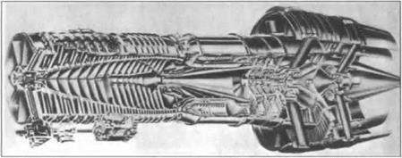
Testing the Engine-A Quantum Jump in Performance The first full engine test of GE’s prototype turbofan engine, then designated the X220, occurred on December 26, 1957, three months after the fan aerodynamic design had been verified. Figure 16 displays the engine. It achieved Blanton’s target of 15,000 pounds of net sea-level-static thrust at a specific fuel consumption below 0.55, and it performed well at off-design conditions. GE had its turbofan engine at remarkably little development cost.
Very quickly a prototype of the CJ805-23 was assembled, and testing to qualify it for commercial flight was initiated. The addition of the aft fan increased the thrust of the CJ805 turbojet by roughly 40 percent, while lowering the specific fuel consumption by as much as 20 percent. The fan added nearly 1000 pounds to the weight of the engine, but, by virtue of achieving the fan performance in a single stage, the thrust-to-weight ratio of the turbofan engine, 4.24, was better than the 4.16 value of the turbojet.68 The best way of appreciating the full
|
Figure 16. General Electric CJ805-23 turbofan engine. [W. Hesse and N. Mumford, Jet Propulsion for Aerospace Applications (New York: Pitman Publishing, 1964), p. 261.] |
magnitude of the advance is to compare the CJ805-23, with its 1.56 bypass ratio, to Rolls-Royce’s Conway RCo.10, with its 0.6 bypass ratio. This model of the Conway was specified to produce 17,000 pounds of take-off thrust at an overall specific fuel consumption of 0.70 with a thrust-to-weight ratio of 3.76.69 The CJ805 could produce nearly as much thrust while consuming better than 15 percent less fuel in a 1200 pound lighter engine. The CJ805-23 created a totally new standard for fuel consumption, and hence operational economy, in commercial flight. In a four-engine transport every pound saved in fuel or in engine weight represents added range or four pounds added to payload. Commercial airlines would never again tolerate the old standard – the turbofan had arrived.70


