The Aft Fan Component
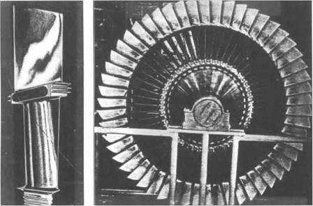
The aft fan required the mechanical design of a new type of blading, with relatively high temperature turbine blades – or, as GE called them, turbine buckets – in the inner portion and relatively cold fan blades of the opposite camber in the outer portion; GE dubbed these blades “bluckets” (see Figure 10). The aerodynamic
|
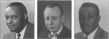
Figure 9. John Blanton, Richard Novak, Linwood Wright, key contributors to General Electric’s aft-fan development. |
design of the turbine blading fell within the state of the art, whether the fan component consisted of one stage or two. But the same was not true of the fan blading. Considerations of weight and simplicity strongly favored a single stage fan. As is always the case, the thermodynamic cycle design of the fan component involved a complex set of trade-offs. The CJ805 turbojet produced 11,000 pounds of take-off thrust at a specific fuel consumption – i. e. pounds of fuel per hour per pound of thrust – around 0.70. Blanton found that a 1.56 bypass ratio aft fan behind the CJ805 could increase the take-off thrust to 15,000 pounds at a specific fuel consumption as low as 0.55, a quantum jump in both parameters! The one issue was the thrust-to-weight ratio of the engine, which depended on the weight of the fan component. The fan would have to pass 250 lbs/sec of air at a pressure-ratio of 1.6 with an installed efficiency no less than 0.82. Could this be achieved in a single stage? It was far beyond any single compressor stage GE had ever designed before, or for that matter any stage that had ever been in flight. Wright was nevertheless insistent that it could be done.54
The detailed aerodynamic design of the fan was predicated on two crucial decisions. The first was to set the tip Mach number of the fan at 1.25. Klapproth’s 1400 ft/sec tip-speed design had shown that the losses in appropriately designed blading correlated continuously with those in conventional blading up to a Mach number of 1.35. Wright’s 1260 ft/sec transonic rotor, which had a design tip Mach number of 1.25, had been predicated on the 90 percent speed results of Klapproth’s design.55 In effect, based on his experience at NACA, Wright decided that losses associated with shocks would not become obtrusive so long as the tip Mach number did not exceed 1.25. His high confidence in the design, which was questioned by several of GE’s experienced compressor designers, came in large part from the safety margin he believed he had introduced in choosing the 1.25 tip Mach number.
Fan Aerodynamic Design-A New Computer Method The second crucial decision was to adopt a novel analytical design approach. A distinctive feature of both Klapproth’s 1400 ft/sec and Wright’s 1260 ft/sec NACA
|
Figure 10. Blucket from General Electric CJ805-23 fan engine. Inner section is turbine “bucket,” drawing energy from jet exhaust, outer section is fan blade, pressurizing bypass flow, hence the hybrid term “blucket.” [Wilkinson, cited in text, p. 32.] |
rotors “was a fairly elaborate three-dimensional design system which allows both arbitrary radial and axial work distributions”56 within the blade row. Just as the annulus or flow area must contract in a high-pressure-ratio, multistage compressor, the flow area within a high-pressure-ratio blade row must contract between the leading and trailing edges far more than in conventional blade rows. Furthermore, high Mach number airfoil profiles are very sensitive to incidence angle. As a consequence, radial equilibrium effects, redistributing the flow radially, becomes important within blade rows in this type of stage, and not just from stage to stage as in more conventional compressors.
One of the first computer programs GE had developed after delivery of its IBM – 704 digital computer in 1955 solved the radial equilibrium problem in multistage axial compressors. The program employed the so-called streamline-curvature method, an iterative procedure for solving the inviscid flow equations. Specifically, an initial guess is made on where the streamlines lie radially in the spaces between each blade row throughout the compressor, and the flow along these streamlines is calculated; the streamlines are then relocated iteratively until the continuity equation is satisfied.57 When used in design, the work done and losses incurred across each blade row are specified as input along the streamlines, and the flow analysis results are then used to select appropriate standard airfoil profiles for the blades.58 Such an iterative approach was out of the question without digital computers, for the total number of calculations required is immense. Even with an IBM-704, the solution for a single operating point of the 17-stage J-79 compressor would take two or three hours, depending on the initial streamline location guess. The advance in analytical capability, however, justified this. The radial redistribution of the flow throughout a multistage compressor could be calculated with reasonable confidence for both design and off-design operating conditions. Streamline-curvature computer programs revolutionized the analytical design of axial compressors.59
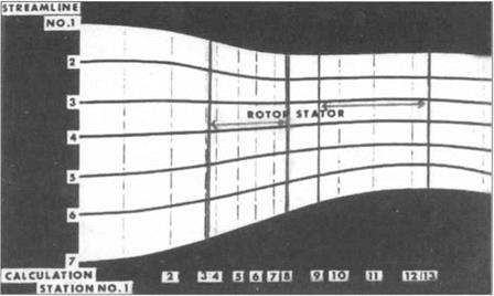
Novak’s strong advocacy of streamline-curvature methods had been one of the chief reasons GE had developed this program in the first place. In the original program radial equilibrium was imposed only in the open spaces on either side of each blade row. Novak now proposed that GE’s streamline curvature program be specially modified to allow radial equilibrium to be imposed at select stations within blade rows. The streamlines and calculation stations for the fan are shown in Figure 11. In effect, the modified procedure “fools the IBM computer into thinking it is going through a series of stators with no swirl in the inlet of the compressor, through a series of rotors with small energy input through the rotor proper, and a series of stationary blade rows when it actually computes through the complete stator.”60 The second key decision in the design of the fan was to modify the streamline-curvature computer program and use it in designing the rotor and stator airfoils.
|
Figure 11. Schematic illustration of streamline curvature method used in fan design (looking sideways at the engine). Initial positions of “streamlines” are assumed, flow conditions are then computed at each of the numbered stations; streamlines are then iteratively relocated until continuity conditions are satisfied. The unusual feature in this diagram is that computational stages aie included within each blade row (i. e. stations 4, 5, 6 & 7 are within rotor). [Wright and Novak, op. cit., p. 5; Figures 11-17 are all from this paper, cited in note 7 of the text.] |
Specifically, the following parameters were specified as input and the requisite shape of the airfoils was inferred from the flow solution: (1) loss or entropy change distributions, both radially and along stream surfaces through the blades and annulus; (2) energy or work distribution radially and along stream surfaces; (3) blade blockage – i. e., a reduction in flow area within the blade rows; and (4) an allowance for boundary layer thickness along the casing wall. The solution determined (circumferentially average) velocities and pressures at each station along the streamlines. Blade surface velocities could then be inferred by assuming a linear cross-channel variation in static pressure; and blade contours were inferred from the (circumferentially average) relative flow angles at each station by assuming a blade thickness distribution and a distribution of the difference between air and metal angles within the blade row.
The choice dictating the values of the aforementioned parameters is based on judgment, prior test data and on a knowledge of the probable mechanical requirements of blade-thickness distribution, and so on…. It is to be recognized from the start that the entire procedure presupposes an iteration, with many variables, to a selfconsistent solution. Hence, each input parameter itself was considered as subject to change.61
No cascade airfoil contours had ever been designed by means of such an elaborate procedure before. The “Arbitrary Blade Contour” Program, as Wright called the modified program, gave him good design control in a design that stood well outside the established state of the art.62
Its complexity and sophistication notwithstanding, this analytical method fell far short of providing a scientifically rigorous or exact calculation of the flow in the fan. First of all, the program was solving the inviscid equations of motion, with viscous losses simply estimated and superposed numerically at calculation stations. In particular, the viscous boundary layers on the blade surfaces were ignored, their effects represented by superposing on the inviscid flow a stipulated sequence of thermodynamic losses distributed linearly with axial distance.63
Second, the actual rotor blades and stator vanes indicated in Figure 11 were not literally included in the analysis. The streamlines shown in the figure were really axisymmetric stream surfaces in the calculation – not just between blade rows, but within them as well. The physical presence of the blades was represented by a numerically superposed blockage of the flow within the blade rows. The velocities and pressure calculated at each axial station within a blade row were accordingly treated within the analysis as if they were uniform around the circumference. The velocities at the blade surfaces were then calculated, in a subsidiary program, by stipulating the number of blades and assuming a linear variation in pressure from one blade surface to the next. The method thus replaced the actual three-dimensional geometry and flow by a highly idealized model; it did not include even a twodimensional blade-to-blade flow solution of the sort that had been promoted by Chung-Hua Wu at NACA.64
Third, no effort was made to determine the precise locations of the shocks, much less to determine their interaction with airfoil boundary layers. The American Society of Mechanical Engineers’ paper by Wright and Novak describing the design of the fan and the method followed never mentions shocks. Yet shocks were surely present, for the design relative incident velocity was supersonic over all but a small fraction of the blade span, ranging from a Mach number of 1.25 at the tip to 0.98 at the hub. The shocks were taken into account only in the input distributions of losses and work specified within the rotor blade row; the shock structure assumed for this purpose was based on two-dimensional Schlieren photographs of the sort shown in Figure 8.
In short, what the analytical method did was to provide a highly idealized analysis of radial equilibrium effects within the blade rows. High Mach number blading is sensitive to deviations in incidence angles. The principal source of such deviations was thought to be radial migration of streamlines within the blade rows and blockage caused by the casing wall boundary layers. The method yielded blade contours in which radial equilibrium effects within the blade rows were consistent, under the assumptions of the analysis, with the computed incidence angles. The inputs assumed in the design were based on judgment and previous test data, reflecting Wright’s experience at NACA. A large number of passes through the design procedure (each requiring more than 20 minutes of IBM 704 computer time) were made, with these inputs changing, before a result emerged that was deemed adequately “selfconsistent.” The analytical method, for all its sophistication, was a tool in a design that remained essentially a product of judgment.
A central element of this judgment was to maintain the diffusion factors across the blade rows within the established limits, subject to Klapproth’s proviso (quoted earlier) that the velocity distributions within the blade rows not depart too radically from those of conventional airfoils. The computer program served to define the radial relocation of the stream surfaces within the blade rows, across which the diffusion factor was calculated, and it helped assure that the design would fall within the regime Klapproth had singled out. How much the blades designed on the basis of it differed from blades that might have been obtained, exercising the same judgment, from the computationally less intensive methods followed by Klapproth and Wright at NACA is an open question.65


