THE EARLY HISTORY OF TURBOFANS. Early Bypass Engines
The propulsion efficiency advantage of turbofans was well-known nearly as long as turbojets themselves. In 1936, before he actually built a working turbojet, Frank Whittle patented a scheme to compress more air than was necessary for the turbine and to force it rearwards as a cold jet. Whittle wished to “gear down the jet” to make it more efficient, maintaining the overall mass-flow while reducing exhaust velocity.10 During the next decade, as Whittle developed the first successful turbojets, he patented several other configurations of bypass engines, including ones with a fan both fore and aft of the rest of the engine (he did not use the term ‘fan’ or ‘bypass’ for any of these designs).11
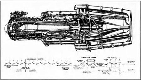
Whittle was not alone among the British in putting preliminary designs of bypass engines on paper. A. A. Griffith of Rolls-Royce devised a multistage axial fan in 1941.12 Figure 4 shows a cutaway of a Metropolitan Vickers turbofan engine from just after World War II in which the fan, consisting of two counter-rotating stages, is located downstream of the core engine, using its exhaust to drive turbine stages to which the fan blades are connected. Figure 5 shows a drawing of a De Havilland bypass engine in which the flow leaving the last stage of the axial compressor is split, with the outer portion bypassing the rest of the core engine and the inner portion proceeding on to a centrifugal compressor, then a combustor, and finally a pair of turbines. We have been unable to determine whether either of these engines was ever built and tested and, if they were, why they died in their infancy.13 Counter-rotating stages are notoriously difficult to make work in anything but the
|
Figure 4. Cutaway view of the Metropolitan-Vickers F-3 turbofan engine, late 1940s. The fan at the rear consists of two counter-rotating stages. [G. Geoffrey Smith, Gas Turbines and Jet Propulsion (London: Iliffe & Sons Ltd., 1955), p. 66.] |
precise conditions for which they were designed – a significant drawback for an operational engine. The De Havilland engine, however, did not reach so far beyond the state of the art. From the perspective of hindsight, the main question about it is whether its compressors, combustor, and turbines performed well enough to provide the energy demanded by the bypass flow in its axial compressor.
These two British engines call attention to one of the two fundamental problems in designing practical bypass engines capable of realizing their theoretical promise. For high-subsonic flight the bypass flow needs to be pressurized to a level around 1.5 times the inlet pressure. The De Havilland design employed 6 axial compressor stages to achieve the requisite pressure in the bypass stream. The Metro-Vick design used counter-rotating stages to try to achieve the requisite pressure in merely two stages, saving weight, but with the risk of being unable to coordinate the flow in the two stages. Thus, one fundamental problem in designing a bypass engine for high-subsonic flight was to achieve the needed pressure rise in the bypass stream without incurring an excessive weight penalty. The later successful turbofan engines shown in Figure 2 used an aerodynamic design technology that did not exist in the late 1940s.
 |
The other fundamental problem in designing a bypass engine was the need for more powerful core engines. The greater the bypass airflow, the more energy that is needed to pressurize it. The core engine must generate this energy using only the air passing through it. Whether the overall engine is a turboprop, turbofan, or turbojet, its core engine consists of a gas generator that converts chemical into mechanical energy. One of the basic performance parameters of gas generators is called specific-power – the power produced per unit of airflow. The specific-power of the aircraft gas turbines of the late 1940s was low, limiting the amount of bypass airflow. As a consequence the most anyone could even hope to achieve in a bypass engine at the time was a small incremental gain over turboprops or turbojets.
Realizing the promise of bypass engines required core engines with significantly higher specific-power. Higher specific-power calls for higher overall engine compression ratios.14 In other words, to make a working bypass engine, the core engine compressor had to achieve markedly higher pressures than the engines of the late 1940s were able to do.
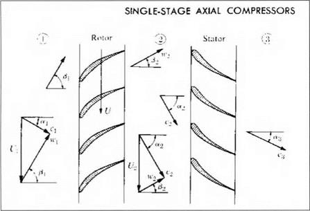
The State of Axial Fan and Compressor Technology These two problems share the common demand of achieving a pressure-ratio, in the one case across a fan and in the other across a compressor. An axial fan stage, however, amounts to nothing but an axial compressor stage. An axial compressor stage consists of a row (or cascade) of rotating blades followed by a row of stationary blades, as shown schematically in Figure 6. Energy is added to the flow in the rotating blade row, while the stationary blade row redirects the flow and recovers the kinetic energy imparted by the rotor, in the process converting the velocity head into pressure. In contrast to a turbine stage, a compressor stage tries to make air do something that it does not want to do, namely flow against an opposing or adverse pressure gradient. The effects of the adverse pressure gradient ultimately limit the pressure-ratio that can be achieved in a single stage; above this limiting
|
Figure 6. Schematic of an axial compresor stage consisting of a row of rotor blades followed by a row of stators. Air flows from left to right. In velocity triangles, w designates absolute air velocity relative to the rotor, c designates absolute air velocity, and U is velocity of the rotor. [P. Hill and C. Peterson, Mechanics and Thermodynamics of Propulsion (Reading, Mass: Addison-Wesley, 1965) p. 245.] |
point, which varies from one airfoil type to another, irreversible thermodynamic losses become excessive. This is why the axial compressors in the engines shown in the earlier figures all had several consecutive stages. It is also why more than one stage was used to pressurize the bypass flow in both the De Havilland and the Metro-Vick engines.
Despite its critical role, axial compressor technology was in its infancy in the 1940s. Not only was the pressure-ratio that could be achieved in any one stage quite low, but also “many early axial compressors worked more as stirring devices”15 instead of achieving compression. Although a base point in axial compressor design technology had emerged in 1945, lending some rationality to the design process, designers remained restricted in the performance demands they could place on the compressor.16 These restrictions in turn limited the performance that one might hope to achieve in a bypass engine by limiting both the pressure-ratio per stage achievable in a fan and the specific-power achievable in the core engine. These same restrictions were limiting the performance of turbojet engines as well. The military was rapidly converting to turbojet-powered aircraft in the late 1940s, with increasing emphasis on supersonic flight. Turbojets for supersonic flight required higher specific-power than the turbojets already flying were achieving.
Because of its role in dictating performance limitations, no component received more research and development effort between 1945 and 1955 than the axial compressor. This effort had three goals: (1) to achieve considerably higher overall compressor pressure-ratios at high thermodynamic efficiency; (2) to increase the predictability of axial compressors, especially at off-design operating conditions, so that fewer compressor designs would turn out to be unacceptable on test; and (3) to increase the pressure-ratio achievable in a single stage so that higher overall compression ratios could be achieved without exacting a penalty in the thrust-to – weight ratio of the engine.17 Although most of this research and development effort was applicable to fans as much as to compressors, the turbofan engine largely disappeared from view during these years. R&D funds went into developing better turbojets, not into transforming the promise of the bypass concept into successful engines.
From the perspective of hindsight, however, this was appropriate even from the point of view of the bypass engine, for the gains that were achieved in gas generator performance in the late 1940s and early 1950s ended up contributing crucially to the first turbofan engines to enter flight service. Moreover, as we shall see below, the advances that were made in compressor aerodynamic design technology during these same years contributed no less crucially to the aerodynamic design of the fans of these engines.


