WHAT IS A TURBOFAN ENGINE?
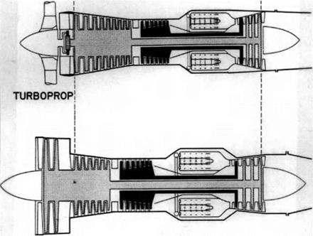
An aircraft gas turbine engine takes in air through an inlet, increases its pressure in a compressor, adds fuel to the high-pressure air and bums the mixture in a combustion chamber, and then exhausts the heated air and combustion products, expanding first through a turbine, where energy is extracted from it to drive the compressor, and finally through a nozzle. Schematics of the three principal types of aircraft gas turbines are shown in Figure 1. In a turboprop engine, the turbine also drives a propeller, connected to the rotor shaft through gears, and it supplies the thrust required by the aircraft; the gas turbine in this case is just an alternative to a piston engine, converting chemical energy into mechanical energy. In a turbojet, by contrast, the thrust comes from the energized flow exiting the nozzle, literally the “jet” of exhaust. In bypass engines a significant portion of the thrust comes from exhaust air that bypasses the combustor and turbine. The bypass air must receive energy from one source or another in order to supply thrust. In the case of a turbofan engine the bypass air is pressurized by a fan. The ratio of the bypass air to the air that passes through the combustor and turbine is called the bypass ratio. Bypass engines are typically classified as low or high bypass in accord with this ratio. One
|
|
|
|
|
|
|


![]()
|
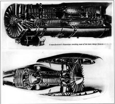
Figure 2. Cutaway drawings of Pratt and Whitney JT8D, a low-bypass turbofan, and General Electric CF-6, a high-bypass turbofan. These engines power numerous modern commercial airliners, including the Boeing 727 and 737 and Douglas DC-9. [Jack L. Kerrebrock Aircraft Engines and Gas Turbines (Cambridge: MIT Press, 1981) p. 19A, Flight Magazine, February 29, 1961.] |
of the two engines on the 737 mentioned above, for example, is an older low-bypass engine, Pratt & Whitney’s JT8D, with a bypass ratio of 1.1 to 1; the other is a more recent high-bypass engine, General Electric’s CF6, with a bypass ratio of 5 to 1 – i. e. less than 17 percent of the total airflow goes through the combustor and turbine. (Hence the shorter, fatter appearance of the larger fan.) Figure 2 displays cutaways of these two engines.
In both turbojet and turbofan or bypass engines, indeed in aircraft engines generally, the magnitude of the thrust is the product of the exhaust mass-flow rate and the difference between the exhaust velocity and the flight speed. Turbojets typically achieve their thrust from a comparatively small mass-flow exiting at a comparatively high velocity. Bypass engines can achieve the same thrust from more mass-flow exiting at a lower velocity. One advantage this gives them is lower
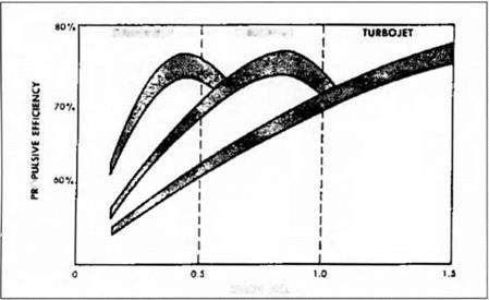
 Figure 3. Typical propulsion efficiency ranges for turboprop, turbofan, and turbojet engines. [L. C. Wright and R. A. Novak, “ Aerodynamic Design and Development of the General Electric CJ805-23 Aft Fan Component,” ASME Paper 60-WA-270, 1060.]
exhaust noise, for exhaust noise is a function of exhaust velocity to the 7th power. Their more important advantage, however, is that they offer higher propulsion efficiency in the range from around 450 to 750 miles per hour. By definition, propulsion efficiency is the fraction of the mechanical energy of the exhaust flow that is realized in propulsion of the vehicle. After a little algebraic manipulation, it turns out that:
2 Vflight
propulsion efficiency = ~——— ———–
‘exhaust ‘flight
Thus, the nearer the exhaust velocity is to the flight velocity, the higher the propulsion efficiency. So long as the components of the engine themselves perform at high thermodynamic efficiency, high propulsion efficiency can be turned into fuel savings.
Figure 3, taken from the technical paper describing the design of General Electric’s first successful turbofan engine7, indicates how propulsion efficiency varies with flight speed for turboprops, turbofans, and turbojets. The propulsion efficiency of turboprops drops rapidly above Mach 0.5, roughly 300 miles per hour, because of increasingly severe aerodynamic losses at the tips of propellers of that era.8 Because of their high exhaust velocities, turbojets do not match the maximum propulsion efficiency of turboprops until they reach flight speeds above Mach 1.
Turbofans are, in effect, hybrids, filling the propulsion efficiency gap between turboprops and turbojets. Just as in a turboprop, the flow leaving the combustor is used in part to drive a fan that supplies thrust from a high mass-flow air stream; the ducting leading into the fan controls the air flow entering it, enabling much higher speeds without the tip losses experienced in propellers. Just as in a turbojet, the thrust is coming from ducted flow exiting a nozzle; but the exhaust velocities are comparatively low in the colder fan stream, resulting in higher propulsion efficiency and hence more thrust for the same fuel consumption.
The emergence of the turbofan engine involved four partly overlapping steps: (1) advances in the turbojet by the engine companies in the late 1940s and early 1950s, leading to a new generation of military jet engines with increased power that later provided core gas turbines for bypass engines (including Rolls-Royce’s Conway, the earliest bypass engine to enter flight service); (2) major breakthroughs in axial compressor aerodynamic design by the NACA in the early 1950s which, though intended primarily for supersonic flight, ended up providing the separate technological bases for the contrasting fan designs of General Electric’s and Pratt & Whitney’s first turbofan engines; (3) GE covertly developing a turbofan engine in 1957 that achieved a quantum jump in flight performance by employing an aerodynamically very advanced single-stage fan, located aft of the core engine; and (4) P&W, in response to GE, rapidly developing in 1958 what proved to be the commercially more successful turbofan engine, with performance comparable to GE’s even though it employed less advanced aerodynamics in a two-stage fan at the front of the core engine.
The fact that these four steps do not form a single, simple evolutionary pathway demonstrates, among other things, the futility of attempting to tell the story of the “first” turbofan. Debates over firsts usually degenerate into questions of definition, and here such an approach would miss much of what is instructive in the episode. The critical historical and epistemological points surface from a number of separate threads of development (several of them not specifically aimed at turbofans), as well as from the interaction of several development projects, particularly those at GE and P&W. In place of the notion of “first,” we deploy and expand ideas of “normal” and “radical” design, which Vincenti proposes based on a schema set forth by Edward Constant.9 Vincenti closely examines normal design, where engineers work to improve performance of technologies whose fundamental layout and principles are established. He has little to say, however, about radical design, in which a new technology’s basic arrangement and function are yet to be determined (he believes, perhaps correctly, radical design to have received undue attention from historians). In the following history of the turbofan, however, we show that normal and radical design can interact, even when producing a final result that is in many respects incremental. The normal versus radical distinction remains clear, but less clear is whether the two must, or can, exist as separate trajectories. To trace their interactions, we shall describe the four steps listed above after briefly reviewing early efforts on turbofan engines and the reasons they did not displace the then existing turbojets.


