BALL NOSE DEVELOPMENT
The heating rates and low pressures encountered by the X-15 ruled out the use of traditional vane-type sensors to measure angle of attack (a) and sideslip (в). Based on a preliminary design completed by Langley in June 1956, NASA awarded a contract to the Nortronics Division of Northrop Aircraft Corporation for the detailed design and construction of a prototype and five production ball noses. The sensor and its supporting, sealing, and hydraulic-actuating mechanisms were an integral assembly mounted in the extreme nose of the X-15. The afterbody located behind the sphere contained the electronic amplifiers, power supplies, and control valves, with the electrical, hydraulic, and pneumatic connections between the sphere and the afterbody passing through a single supporting member. Rotary hydraulic actuators provided the required two degrees of freedom.-1174!
Officially called the "high-temperature flow-direction sensor," the device was 16.75 inches long with a base diameter of 13.75 inches. The total weight of the ball nose was 78 pounds, half of which was contributed by the thick Inconel X outer skins of the lip, cone, and sphere. In addition, 13 chromel-alumel thermocouples were located within the sphere to measure skin temperature during flight, and five other thermocouples measured selected internal temperatures. Nitrogen gas from the aircraft supply cooled the sensor. The ball nose was physically interchangeable with the standard NACA flight-test boom nose, and all connections to the sensor were made through couplings that automatically engaged when the ball nose (or boom) was mounted to the aircraft.-1173
|
|
The ball nose, or more officially, the high-temperature flow-direction sensor, was mounted on the nose of the airplane and provided angle of attack and angle of sideslip information to both the pilot and the research instrumentation. This elaborate mechanism was required since the pressure and temperature environment encountered by the X-15 ruled out more conventional vane-type sensors. (NASA)
The core of the ball nose consisted of a 6.5-inch-diameter Inconel X sphere mounted on the extreme tip of the X-15 nose. The sphere contained two pairs of 0.188-inch diameter orifices (one pair in the vertical plane (a orifices) and one pair in the horizontal plane (в orifices)), each 42 degrees from the stagnation point. Two functionally identical hydraulic servo systems, powered by the normal X-15 systems, rotated the sphere about the a and в axes to a position such that the impact pressures seen by all sensing orifices were equal. When this condition existed, the sphere was oriented directly into the relative wind. Two synchro transducers detected the position of the sphere with respect to the airframe, and this signal fed the various instruments in the cockpit and the recorders and telemetry system. Since the dynamic pressure during flight could vary between 1 psf and 2,500 psf, a major gain adjustment was required in the servo loop to maintain stability and accuracy. Measuring the pressure difference between the total-pressure port and one anglesensing port provided a signal that adjusted the gain of the sphere-positioning loop. The ball nose could sense angles of attack from -10 to +40 degrees, and angles of sideslip within 20 degrees. The unit was capable of continuous operation at a skin temperature of 1,200°F. A 0.5- inch-diameter orifice located at the sphere stagnation point provided a total pressure source for the aircraft. Based on ground tests, the angular accuracy of the sensor was within 0.25 degree for dynamic pressures above 10 psf.^176
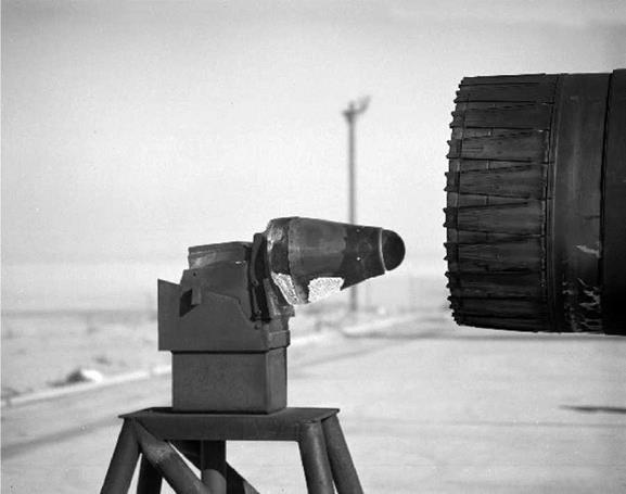
In early 1960 the FRC developed a simple technique for thermal testing the newly delivered ball noses: expose them to the afterburner exhaust from a North American F-100 Super Sabre. This seemed to work well until one of the noses suffered a warped forward lip during testing.
Engineers subsequently determined the engine was "operated longer than necessary," resulting in temperatures in excess of 2,400°F instead of the expected 1,900°F. Ultimately, the FRC tested the ball nose "many consecutive times" with "satisfactory results.”^1771-
The ball nose performed satisfactorily throughout the flight program, encountering only occasional minor maintenance problems. Late in the program, various parts began to wear out, however, and the need to replace some of them presented difficulties. For instance, the procurer of replacement dynamic-pressure transducers found that the original vendor was not interested in fabricating new parts, and no suitable alternate vendor could immediately be located. Eventually
NASA found a new vendor, but this illustrates that the "vanishing vendor" phenomenon frequently encountered during the early 21st century is not new.[178]
|
|
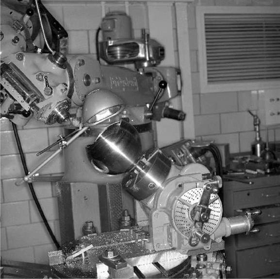
The sphere mounted on the extreme nose of the ball nose was machined from Inconel X to very precise tolerances. The X-15 was manufactured before the advent of modern computer – controlled milling machines, so such precise work was accomplished by human operators on traditional lathes and drill presses. The ball noses for the X-15A-2 were manufactured from TAZ – 8A cermet since the temperatures in the Mach 8 environment were even more severe. (NASA)
As the modified X-15A-2 was being prepared for flight, however, there began a concern over whether the Inconel X sphere in the original ball noses could handle the additional heat generated at Mach 8. Researchers at NASA Lewis developed a TAZ-8A cermet that Rohr Corporation used to manufacture a new sphere specifically for the X-15A-2. This sphere was delivered in mid-1966, but did not initially pass its qualification test due to a faulty braze around the beta pressure port. Rohr subsequently repaired the sphere and it passed its qualification test. Interestingly, the FRC tested this new sphere (and the forward lip of the cone, which was also manufactured from TAZ – 8A) in much the same way as the original ball noses were qualified—this time in the afterburner exhaust of a General Electric J79 engine at 1,850°F. During November 1966, the FRC tested the new sphere, as well as a slightly modified housing necessary to accommodate the ablative coating on the fuselage, in the High-Temperature Loads Calibration Laboratory. NASA installed the new
|
nose on X-15A-2 to support flight 2-52-96 on 21 August 196 7.-1179
|
The ball nose had to withstand pressures up to 2,500 psf and temperatures up to 1,200°F. NASA researchers developed a relatively straight-forward heating test using the afterburned exhaust of a jet engine on the ramp at the Flight Research Center. The original ball noses were tested using Pratt & WhitneyJ57 engines from North American F-100 Super Sabres, while the later X-15A-2 noses used General Electric J79 engines from Lockheed F-104 Starfighters. (NASA)
The ball nose only provided angle of attack, angle of sideslip, and total pressure; like all aircraft, the X-15 needed additional air data during the landing phase. North American had installed a total-head tube (also called the alternate probe) ahead of the canopy to provide the total pressure during subsonic flight, and static pressure ports were located on each side of the fuselage 1 inch above the aircraft waterline at station 50.[180]
A different pitot-static system was required for the X-15A-2 since the MA-25S ablator would cover the normal static locations. Engineers chose a vented compartment behind the canopy as the static source, and found it to be suitable during flight tests on the X-15-1. The standard dogleg pitot tube ahead of the canopy was replaced by an extendable pitot because the temperatures expected at Mach 8 would exceed the thermal limits of the standard tube. The retractable tube remained within the fuselage until the aircraft decelerated below Mach 2; the pilot then actuated a release mechanism and the tube extended into the airstream. This was very similar in concept to the system eventually installed on the space shuttle orbiters.-1181


