PARACHUTE SYSTEMS
Another of the problems that needed to be addressed by Langley’s Flight Research Division – prior even to the formation of the STG – had been the development of a reliable parachute system for a manned space program. Beginning in October 1958 a progressive series of air tests were carried out to assess the deployment, reliability and specifications of a number of different parachute systems.
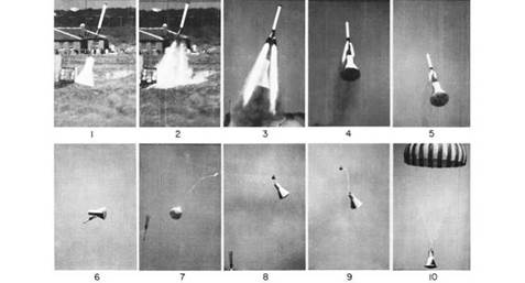
The first air drops were conducted as a means of studying the free-fall stability of the spacecraft, parachute shock loads, and the operation of the capsule’s escape system. Initial tests were carried out by the Pilotless Aircraft Research Division at the High Speed Flight Station, Edwards AFB, California, in order to collect data on opening characteristics and shock loads associated with the drogue chute. Once this information had been gathered and collated, the test engineers’ attention turned to the size and performance characteristics of the main parachute. This had to be large enough so that the final impact velocity of the capsule might be kept at about 30 feet per second.
|
A D-shape capsule features in this sequence of photographs from a beach abort launch-to parachute test on 13 April 1959. (Photo: NASA/Langley Research Center) |
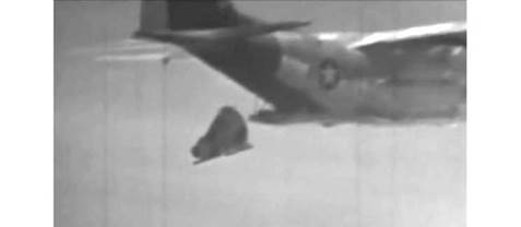
In order to demonstrate the adequacy of the mechanical system in deploying the drogue and main parachutes, preliminary drops were made from NASA helicopters at West Point, Virginia. These utilized concrete-filled drums attached to the operating canister system. Following these tests, a Lockheed C-130A Hercules cargo aircraft was supplied by the Tactical Air Command for the continuation of tests, now involving both high – altitude and low-altitude drops.
Initially, low-level drops were carried out in the vicinity of Pope AFB, near Fort Bragg in North Carolina, to perfect the best means of extracting a full-scale capsule equipped with operating parachute systems from the open tail ramp of the C-130. Once these had been completed, the research and development program moved on to Wallops Island, Virginia, where further drops were carried out under the auspices of Langley’s Flight Research Division. The advanced tests were planned to study the stability of the Mercury capsule both during free flight and with parachute support, shock input into the capsule by the parachute, and retrieval operations. Four drops were completed from altitudes ranging up to 23,000 feet, with parachute openings at up to 15,000 feet. These successful tests demonstrated that with properly designed equipment, there was no impediment to recovery helicopters being utilized in the retrieval operation.
Subsequent air drop tests were completed at various altitudes to investigate the stability of the capsule using a 6-foot FIST (Flugtechnisches Institut Stuttgart) Ribbon drogue parachute in combination with a 67-foot extended skirt main chute. These indicated that a different type of main chute would offer greater reliability. Ring-sail parachutes were substituted, and the drop-test program continued. The results of these tests concluded that a ring-sail parachute would have the desired reliability.
Six succeeding drops using a 6-foot FIST drogue and the 63-foot ring-sail main canopy were all successful. It was decided that this parachute combination worked best and could be used throughout the Mercury program.
|
This blurred, long-distance image taken from film footage of a drop test shows a Mercury boilerplate being jettisoned from a C-130 airplane. (Image: NASA) |
|
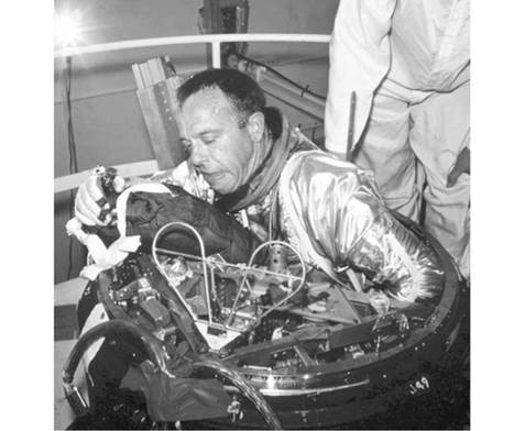
Alan Shepard demonstrates what an incredibly tight and difficult squeeze it was for an astronaut to egress through the top of a Mercury capsule in his space suit. (Photo: NASA) |
As Max Faget explained, “What happened was, the upper part of that capsule held the parachutes. There were two parachutes, the main parachute and the backup, which were identical – completely identical. Even the systems were all identical. They had their own drogue parachutes and pilot parachutes and everything else, but we never had to use the backup system. And there was a hatch up in front, up at the top. If you were sitting in the capsule on the pad – of course, it’s a cone around you like that – right up there would be this hatch, and that was nothing but a dish that was held in place, more or less, by the pressure, although it had a few latches, an inwardly opening door, which made it very light, and, of course, it was dish-shaped, so that it was just about as light as you could make it.
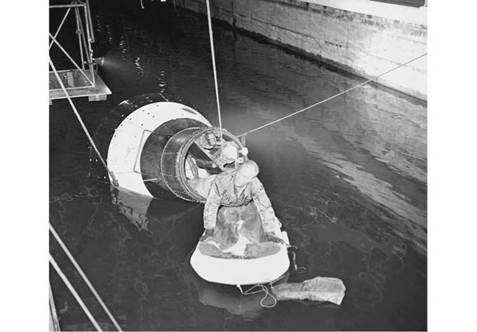
“So when the thing got on the water and [was] floating upright, you could unfasten this dish and push the containers for the parachute, just push them out; they’d fall overboard, and you could get out…. Well, the astronauts did not like the idea of being trapped in this thing, so they complained about it, and we put this explosive bolt device on the side there, which had to be [powered] on and then fired.
“The hatch that they went into was fastened with something like about fifty or sixty small bolts, so it really wasn’t a hatch, it was just a covering. So they were essentially sealed in the capsule.”26
|
John Glenn demonstrates the egress technique in a test tank. (Photo: NASA) |
In fact, as revealed in NASA’s configuration specifications to McDonnell for the Mercury capsule, there were actually 70 bolts in the emergency egress hatch:
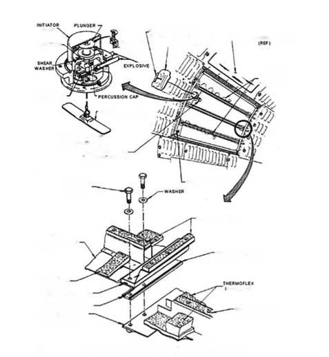
3.5.3 ENTRANCE AND EMERGENCY EGRESS HATCH – The entrance and emergency egress hatch, in accordance with Drawing No. 45-35003, located in the capsule conical section, shall be trapezoidal in shape as dictated by the capsule configuration. The hatch assembly shall be of a construction similar to the basic capsule structure, designed to permit entry into, and emergency egress from, the capsule. An explosive assembly, in accordance with Drawing No. 45-35701, shall be incorporated in the hatch assembly to serve as a means, when ignited, of breaking the seventy (70) hatch attachment bolts. The explosive assembly shall be mounted about the hatch perimeter and shall consist of a gasket type sill containing a continuous single strand of explosive charge to effect severance of the attachment bolts. The strand shall be ignited from both ends simultaneously to provide redundancy. A push-button initiator, located on the hatch interior to the astronaut’s upper right, shall, after removal of a safety cap and pin, ignite the explosive charge when pushed by the astronaut. A pull initiator assembly shall be provided for ground rescue utilization on the exterior of the hatch beneath the shingles. Function of the pull initiator assembly shall be the same as for the astronaut-actuated initiator. The hatch assembly shall be secured to the capsule structure by two wire springs, in accordance with Drawing No. 45-35058. These springs shall absorb the energy expended by the explosive charge and serve to prevent injury to personnel working in the hatch area during recovery operations.27
 EXPLOSIVE CHARGE
HATCH INNER SEAL
 |
||
CAPSULE HATCH SILL
LIBERTY BELL 7 • (MERCURY 4) HATCH DIAGRAM
Diagram of the MR-4 hatch. (Illustration: NASA)


