SPACE TASK GROUP
On 5 November 1958, NASA’s Space Task Group, or STG, was created, reporting directly to the Director of Space Flight Development at NASA Headquarters in Washington, D. C. With Robert Gilruth at its head, the STG originally comprised of 27 engineers from the Langley Research Center and another 10 from the Lewis Research Center, plus eight secretaries and “computers.” The latter designation was applied to women who ran calculations on mechanical adding machines. They all served as the nucleus for the work carried out on Project Mercury.
As the head of the STG, Gilruth was responsible for reporting to Dr. Abraham (‘Abe’) Silverstein, NASA’s Director of Space Flight Development, who in turn reported to the agency’s Administrator, Dr. T. Keith Glennan. The STG included Charles Donlan (Gilruth’s deputy); Chuck Mathews (head of flight operations); Chris Kraft (also in flight operations); and Glynn Lunney, who at age 21 was the youngest member of the group. The head of the public affairs office was Lt. Col. John (‘Shorty’) Powers.
|
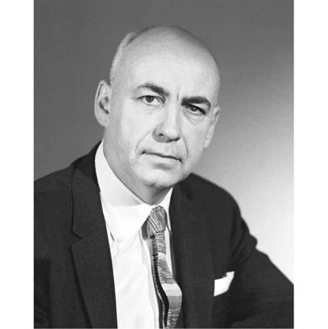
Dr. Robert R. Gilruth. (Photo: NASA) |
Work had already begun on the writing of detailed specifications for a Mercury capsule even while the group was still designated as the NACA. By the end of October 1958 a preliminary draft had been completed.
On 17 December 1958 NASA issued an official statement in which the space agency announced the formation of Project Mercury and outlined the program’s objectives:
1. To put a manned space capsule into orbital flight around the Earth.
2. To recover successfully the capsule and its occupant.
3. To investigate the capabilities of man in this new environment.
Flight Plan
1. An intercontinental ballistic missile rocket booster will launch the manned capsule into orbit.
2. A nearly circular orbit will be established at an altitude of roughly 100 to 150 statute miles to permit a 24-hour satellite lifetime.
3. Descent from orbit will be initiated by the application of retro-thrust rockets incorporated in the capsule system.
4. Parachutes, incorporated in the capsule system, will be used after the vehicle has been slowed down by aerodynamic drag.
5. Recovery on either land or water will be possible.
Description of Manned Capsule System
1. Vehicle. The manned capsule will have high aerodynamic drag, and will be statically stable over the Mach number range corresponding to flight within the atmosphere. The capsule, which will be of the nonlifting type, will be designed to withstand any known combination of acceleration, heat loads, and aerodynamic forces that might occur during boost or reentry. It will have an extremely blunt leading face covered with a heat shield.
2. Life Support System. A couch, fitted into the capsule, will safely support the pilot during acceleration. Pressure, temperature, and composition of the atmosphere in the capsule will be maintained within allowable limits for human environment. Food and water will be provided.
3. Attitude Control System. A closed loop control system, consisting of an attitude sensor with reaction controls, will be incorporated in the capsule. The reaction controls will maintain the vehicle in a specified orbital attitude, and will establish the proper angle for retro-firing, reentry, or an abort maneuver. The pilot will have the option of manual or automatic control during orbital flight. During manual control, optical displays will permit the pilot to see portions of the Earth and sky. These displays will enable the pilot to position the capsule to the desired orbital attitude.
4. Retrograde System. A system will be provided to supply sufficient impulse to permit atmospheric entry in less than one half an orbital revolution after application of the retro-rockets. These rockets will be fired upon a signal initiated either by a command link from ground control or by the man himself. The impact area can be predetermined because of this control over the capsule’s point of reentry into the atmosphere.
5. Recovery System. As the capsule reenters the Earth’s atmosphere and slows to a speed approximately that of sound, a drogue parachute will open to stabilize the vehicle. At this time, radar chaff will be released to pinpoint the capsule’s location. When the velocity of the capsule decreases to a predetermined rate, a landing parachute opens. The parachute will open at an altitude high enough to permit a safe landing on land or water. (The capsule will be buoyant and stable in water.) After landing, recovery aids will include: tracking beacons, a high-intensity flashing light system, a two-way voice radio, SOFAR [Sound Fixing and Radar] bombs and dye markers.
6. Escape System. In an emergency situation before orbital altitude is reached, escape systems will separate the capsule from the booster. After the capsule is in orbit, the space pilot can reenter the atmosphere at any time by activating the retro-rockets. Other safety control features will be incorporated.
Guidance and Tracking
Ground based and booster equipment will guide the capsule into the desired orbit. Ground and capsule equipment will then determine the vehicle’s orbital path throughout its flight. The equipment will be used to initiate the vehicle’s descent at the proper time and will predict the impact area.
Communications
Provisions will be made for two-way communications between the pilot and ground stations during the flight. Equipment will include a two-way voice radio, a receiver for commands from the ground, telemetry equipment for transmission of data from the capsule to ground stations, and a radio tracking beacon. This communications equipment is supplemented by the special recovery aids.
Instrumentation
1. Medical instrumentation to evaluate the pilot’s reaction to space flight.
2. Instrumentation to measure and monitor the internal and external capsule environment, and to make scientific observations. Note: Data will be recorded in flight and telemetered to ground recorders.
Test Program
As in the case of new research aircraft, orbital flight of the manned space capsule will take place only after the logical buildup of vehicle capabilities and scientific data. Project Mercury includes ground testing, development and qualification flight testing, and pilot training.


