The Elliptical Distribution of Lift
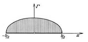
Ideally the shape of the graph of Г(х) showing the distribution of circulation, and hence lift, along the span of the wing, would be deduced from first principles. The deduction would start with the governing equations of fluid motion and, by inserting data about the shape of the wing and the angle of attack, the mathematics should yield the function Г(х) relating the circulation to the x-coordinate along the span. This, said Prandtl later, was the first question that he and his group posed for themselves but the last one to be answered. (During the war the problem was solved for a rectangular wing by Betz. His analysis formed the substance of a 1919 inaugural dissertation submitted to Gottingen.)73 Initially, however, it was necessary to proceed by trial and error and under the guidance of experiment. The character of the lift distribution along the wingspan could be established empirically by pressure measurements made on a model of the wing in a wind channel. If a mathematical representation could be found for the distribution, and if that function could be integrated, then the equations of the theory (given in the last section) could be employed to deduce further characteristics of the wing. The function Г(х) governing the distribution of circulation had to be (1) empirically plausible and (2) mathematically tractable. Experimentally it transpired that most of the wings used in practice had a similar distribution of lift and hence circulation along their span. There was a strong “family resemblance” between their distributions, and the family in question was well known.74 The distribution typically resembled the upper half of an ellipse. The expression Г(х) is essentially nothing more than the equation for an ellipse.
The equation for an ellipse is simple. Using standard x – and y-coordinates,
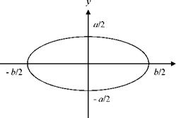
the ellipse that has a major axis of length b in the x-direction and a minor axis of length a in the y-direction is represented by the equation
f—T+(—T=l
1 b/2 j fa/2j
The ellipse is shown in figure 7.12a. If the y-axis is used to represent the circulation, then the formula describing an elliptical distribution of circulation of the kind shown in figure 7.12b is, by analogy,
The ellipse has one semi-axis of length Г0 (the maximum circulation) and the other semi-axis of length b/ 2 (the half span). This formula can be manipulated
![]()

![]()

![]()
 (a)
(a)
Tietjens 1931, 213. (By permission of Springer Science and Business Media)
to give an expression for Г (as a function of x). An elliptical lift distribution is thus given by
rM■
With this formula at hand, the reasoning set out in general terms in the previous section can be reworked to produce quantitative predictions about lift and induced drag. Following this line of reasoning, Prandtl was able to generate three important results. First, he showed that the induced drag along the span of a wing should be constant if the distribution of circulation is elliptical. Second, he showed that under these conditions the induced drag should increase according to the square of the lift coefficient. Third, he predicted a relation between the induced drag and the planform of the wing. He showed that induced drag should be inversely proportional to the aspect ratio. The narrower the wing, the lower the induced drag. This result had immediate implications for the aircraft designer. I shall now show how he reached these conclusions mathematically and then say more about their importance.
Differentiation of the formula for Г(х) gives the expression dr/dx, and the result can be substituted into the formula for the induced velocity, or downwash, that was arrived at in the previous section. The differentiation of the elliptical distribution gives
dr 4Г0 x
dx b (l-4×2/ b2 )1/2’
The induced velocity is then
p +b/2
![]() —у f —– ^—– dx.
—у f —– ^—– dx.
nb — b/2 (l — 4×2/b2) )x’ — x)
The next problem was to evaluate the complicated-looking integral in order to give an actual value to the downwash. It turned out that the integral reduced to a very simple expression. It was equal to – nb/2. The induced velocity at the point x’ of the wing was then
Г
^’)=—20.
The induced angle of incidence for this point on the wing follows immediately:
w Г
q>(x’) = = ——.
V 2bV
Two features of these formulas for w and ф deserve notice. First, inspection shows that all the quantities that enter into them are constants. The span of the wing, the speed of the free stream, and the value of the circulation at the center of the wing do not change as different positions along the span come under consideration. Both expressions are therefore independent of x’. It follows that for any given wing, provided it has an elliptical lift distribution, both the induced velocity and the induced angle of incidence are constant along the span. The unreal, infinite, induced velocities at the wingtip have been avoided. This was progress.
The second point of note is that both of the formulas have b, the span of the wing, in the denominator. Thus, as b approaches infinity, both w and ф approach zero. The theory therefore implies that for an infinite wing there will be no downwash, that is, no induced velocity, and thus no induced drag. This fits perfectly with the previous work of Kutta and Joukowsky. For an infinite wing moving through an ideal fluid, the absence of induced drag means the absence of all drag, and this was one of the more disconcerting consequences of their analysis. However, the results of the two-dimensional theory turn out to be a limiting case of the more realistic, three-dimensional theory. On Prandtl’s approach, Kutta and Joukowsky were not studying the unreal aerodynamics of an imaginary world; they were studying the aerodynamics of the real world but dealing with limiting cases.
The value of the circulation Г(х) given earlier by the formula for the elliptical distribution can be inserted into the Kutta-Joukowsky law. This gives an expression for the total lift of a wing with an elliptical distribution:
Lift = pVT0 J I 1 – — I dx ■
A change of variable simplified the integration and gave Lift = pVT0
If the lift is now expressed as a coefficient and the equation is rearranged to give an expression for Г0, the maximum circulation, it becomes
2VFCl
![]() bn
bn
where F is the area of the wing. This value of Г0 can be inserted into the previously derived expression for the induced angle of incidence, which gives
.C
nb2
This expression yields a relation between the induced angle of incidence and the planform of the wing.
Because of its importance it is worth making this relation explicit and restating the formula. For a rectangular wing of, say, span b and chord a, the area F = ab and the aspect ratio is b/a. This definition of the aspect ratio can be generalized for more complicated shapes. For wings that do not have a constant chord, the chord length can be replaced by F/b, that is, the area divided by the span, thus giving the aspect ratio as b2/F. If the aspect ratio is represented by the symbol AR, then the above formula for the induced angle of incidence becomes
This expression reaffirms the point made previously—that for a wing with an elliptical distribution, the induced angle of incidence will be constant along the span. The utility of the new formulation, however, is that it leads to a revealing expression for the induced drag. To arrive at this result it is only necessary to insert the above expression for ф into the formula for the coefficient of induced drag given previously. In the last section it was shown how Prandtl’s theory had given the following general result for the coefficient of induced drag:
2 +bl2
CD = — J Г(х)(p(x)dx.
Because an elliptical distribution for the circulation has been assumed, all of the component parts of this integral are now known. The expression for ф is a constant whose value has just been expressed in terms of the aspect ratio. It can thus be taken out from beneath the integration sign. The remaining integral of the elliptical shape Г(х) has already been evaluated. These results
can be combined so that (again using AR to signify the aspect ratio) the coefficient of induced drag can now be written in the form
This formula expressed a highly significant result. It indicated two things. First, it showed that the induced drag increases rapidly with increased lift. The drag grows with the square of the lift coefficient. Second, it implied that to reduce the drag it was necessary to increase the aspect ratio of the wings. It therefore carried an important lesson for the aircraft designer because it linked a specific design feature of a wing to definite aerodynamic effects. The significance of the aspect ratio of a wing had long been recognized at an empirical level, but now a fundamental, theoretical understanding was emerging.
This deeper understanding had a typically engineering character to it. It identified the need to trade one advantage against another advantage. It pointed to the costs that had to be paid and the compromises that had to be made to get the benefits of increased lift and decreased drag. Increased lift brought increased induced drag. Induced drag could be reduced by increasing the aspect ratio, but an engineer would immediately see a problem. High aspect ratio may be desirable, but a long, narrow wing is not easy to build. Such a wing confronts the designer with the problem of how to make it strong enough without making it too heavy.


