Section iii. the circular curved surface
Kutta now carried out the procedures for which he had prepared the ground. He began on the z-plane and specified the detailed geometry of the wing. It was to be an arc of a circle of radius r subtending an angle of 2a. This gave the coordinates of the endpoints A (the leading edge) and B (the trailing edge). The straight-line distance between A and B was the “chord,” and the highest point of the arc was to be 1/12 of the chord. Kutta chose to place this highest point at the origin of the coordinate system. He then began the process of transformation. First he used a transformation in which every point was replaced by its reciprocal. Points on the z-plane were linked to those on the z’-plane by the formula z’= 1/z. This had the effect of turning the finite, circular arc into what appeared to be two straight lines. One of them ran parallel to the positive part of the x-axis while the other ran parallel to the negative part of the x-axis. Both were at the same height above the axis. They started at equal distances from the y-axis (that is, there is a gap in the middle), and the lines went off to infinity in opposite directions.
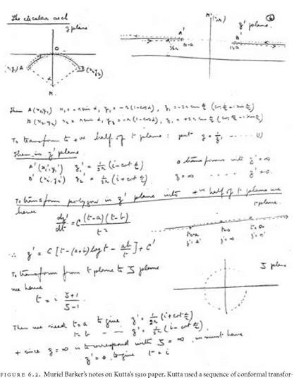
It would have helped the reader of Kutta’s paper if, at this point, he had provided a diagram. Given the pedagogic values of the technische Hoch – schulen, he would surely have drawn pictures of such transformations on the blackboard when he presented them in lectures. Most mathematicians reading such a paper would sketch the appropriate figures, at least until the transformation had become routine for them. To help us follow Kutta’s argument, I exploit an example of this practice. Sometime in the 1920s a young Cambridge mathematics graduate named Muriel Barker had occasion to work through Kutta’s article. She carefully wrote out the reasoning, some-
|
mations to map the flow around a circular cylinder onto the flow around a circular arc representing the wing of Lilienthal’s glider. (By permission of Dr. Audrey Glauert) |
times filling in the steps needed to get from one line to another. She also sketched the conformal transformations. These handwritten notes have survived, and one page from them, containing the sketches, is reproduced here as figure 6.2. Muriel Barker will appear again, later in the story, when the reasons for her interest become apparent. For the moment her notes can help us follow Kutta’s thought processes.
On the top left of the page of the notes is a figure labeled z-plane. It is a drawing of the Kutta-Lilienthal wing with the leading edge labeled A and
the trailing edge labeled B. The effect of the transformation z’ = i/z is shown next to it in the diagram, on the top right of the notes, labeled z’-plane. Notice how the arc has become two straight lines and the leading and trailing edges A and B of the wing have become the endpoints A’ and B’ of the lines. Following his overall plan, Kutta next mapped these lines onto the t-plane where it would eventually link up with the transformed circle. This he did by using the Schwarz-Christoffel transformation. I have described how this transformation played an important role in the mathematical development of the theory of discontinuous flow. It was central to Greenhill’s massive report on this theory for the Advisory Committee for Aeronautics. Kutta used the transformation in a different way and in the service of the circulation theory. He needed it to construct the central arch of his mathematical bridge. The formula of the transformation can be seen about halfway down the page of notes in figure 6.2. It takes the form
The letter C is a constant, and a and b correspond to the endpoints of the wing. Immediately to the right of the formula is a sketch of the result of the transformation produced by applying this formula. The lines on the z’-plane have become the axis of the t-plane. The new line is shown as dotted in the figure, and the points corresponding to A’ and B’ have been marked in. All that was needed now was to work from the other end in order to map the circle onto the t-plane. The inferential bridge would then have been constructed according to plan. The circle in the Z-plane is drawn on the bottom right-hand corner of the notes. The formula
![]() Z+1
Z+1
Z-1 is the transformation linking Z and t. This can be seen in the notes standing to the left of the drawing of the circle. Kutta’s aim might be described as getting from the figure at the bottom right to the figure at the top left of the page, but because he could see no way of doing this directly, he made the transition indirectly, by means of the other figures.
Coming back from the Barker notes to the original paper, we see that Kutta was now in a position to evaluate the constants in his formula in terms of the assumed velocity and direction of the free stream relative to the wing. He could also arrive at a value for the circulation on the assumption that the trailing edge is a stagnation point, that is, that the flow does not have to curl around the rear edge. This gave him the following expression for the
all-important circulation, which, in the notation used by Kutta, is 2ПС. The formula came out as
Circulation = 4nVr sin—sin I —+B,
2 ^ 2 H)
where V is the velocity, a the half angle of the arc that constitutes the wing, and в the angle of incidence of the wing to the free stream. The circulation is thus calculable from known or knowable quantities.


