Category Soviet x-plenes

Bolkhovitinov S

Purpose: Ultra-fast attack bomber.

Design Bureau: WIA (air force engineering academy) located at the Zhukovskii Academy, Moscow, where Viktor Fedorovich Bolkhovitinov was Professor of Aircraft Design and head of design team.

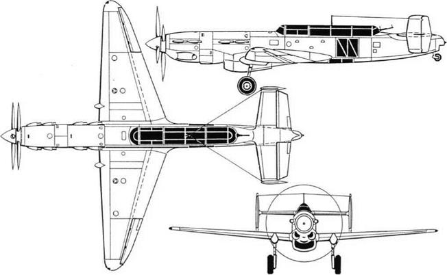
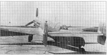
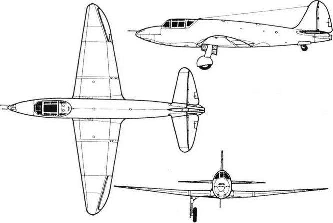
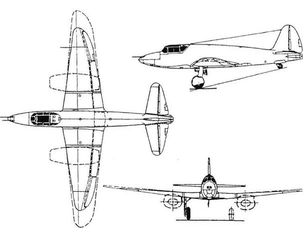
The objective was to make the fastest bomber in the world, by using a fighter-type layout with two powerful engines in tandem. This arrangement was adopted in order to achieve engine-out safety with minimum drag. Design of the propulsion system began in 1936 and of the aircraft itself a year later. The designation stood for Sparka (Twin), but other designations were S 2M-103 (in usual Soviet style, showing the engines), BBS-1 (short-range bomber, fast, the S here mean­ing Skorostnii, speedy) and LB-S (light bomber, twin). Construction of the single pro­totype began in July 1938, the first flight was made by B N Kudrin in late 1939, and NIl-WS testing took place between March and July 1940, the pilots being Kudrin and AIKa – banov. It was found that take-off run was ex­cessive. In 1940-41 the aircraft was subjected to major modifications. ZI Itskovich re­designed the wing with increased area and a changed aerofoil profile. A different front en­
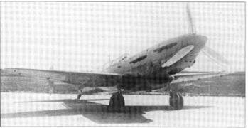
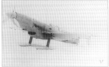
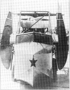
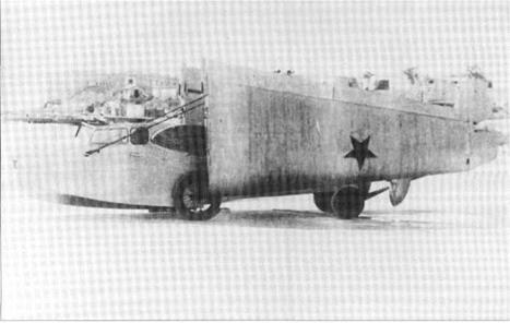
gine was fitted, and the rear engine and its propeller were replaced by an inert mass. The oil coolers were incorporated in the main radiator duct. As the redesigned aircraft neared completion snow was still on the ground, and the landing gears were all re­placed by fixed skis.

No way was found to make proper use of the bay previously occupied by the rear en­gine, and in any case performance was now unimpressive. After the German invasion work was abandoned. Plans for an improved S bomber and a derived I (or I-1) fighter with two M-107 engines were also dropped.

The airframe was entirely a modern light – alloy stressed-skin structure. The wing was based on a structural box with two plate spars with flanged lightening holes, sheet ribs and heavy upper and lower skins with flush rivet­ing. The fuselage basically comprised top, bottom and side panels all joined to four strong angle-section longerons (Shavrov: ‘later this construction was used for the IL-28’, a post-war jet bomber). The twin-finned tail had thin Dl skin throughout, the rudders hav­ing inset balanced hinges, the tailplanes being pivoted and driven by irreversible trim­ming motors and the elevators having trim tabs and a variable geared drive. Each main
landing gear retracted electrically back­wards, the wheel turning through 90°.

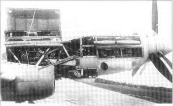
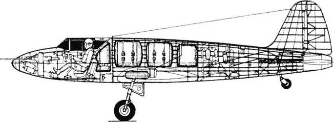
The 960hp M-103 engines (V-12 liquid – cooled derived from the Hispano-Suiza 12Y) were mounted in tandem, the rear engine dri­ving the rear unit of the contra-rotating six – blade propeller. Some reports state that the drive was taken via left/right twin shafts past the front engine’s crankcase, but in fact (as in the Italian Macchi M. C.72 racing seaplane of 1933) the rear engine drove a single shaft be­tween the front-engine cylinder blocks which finally passed through the centre of the front – engine propeller shaft. Both engines were served by a large ducted radiator with a con­trollable exit flap (this was positioned by one of the 29 on-board electric actuators) and two oil coolers were fitted in ducts on each side of the front engine. Four fuel tanks were housed between the wing spars, and on the trailing edge were electrically driven slotted flaps (in several reports, incorrectly called Fowler

type).

Pilot and navigator sat in tandem, far apart under a long Plexiglas canopy. The navigator also had a bomb sight, and the entire area around his seat was skinned in Plexiglas. Turning to the rear he could fire a 7.62mm ShKAS, and it was the intention later to re-
Подпись:

place this by twin 12.7mm UBT. Behind the rear spar, under the pilot’s cockpit, was a bay housing 400kg (882 Ib) of bombs, with two electrically driven doors. It was the intention later to fit fixed guns in the wings.

The second wing, of NACA-230 profile, gave improved field length. One report states that a remotely controlled ShKAS was added in the extreme tail, but this does not appear in any known photographs. Continued poten­tially dangerous problems with the rear en­gine and its drive resulted in this being removed. The front engine was changed to an M-l 05P, ofunchanged 960hp, driving a sin­gle three-blade propeller. Even with weight considerably reduced the S was then judged a failure, though tandem-engine studies con­tinued. The factory was tooled up for Pe-2 production.

Though an article by Ing V Mikhailov and Ing VPerov states that, following initial Nil testing ‘the design team was instructed to continue development’, there is no doubt the S was always on the verge of success but never getting there. The high wing loading and the failure to solve the rear-engine drive problem made it one of the programmes abandoned after the invasion of June 1941.

Dimensions

Span (original)

11.38m

37 ft 4 in

(new wing)

12.2m

40 ft X in

Length (original)

13.2m

43 ft 4 in

(one engine)

13.0m

42ft73/iin

Wing area (original)

22.9 m2

246.5ft2

(new wing)

23.43m2

252.2 ft2

S (as built)

Bolkhovitinov S


Bolkhovitinov S

S (as built).


Bolkhovitinov S

S (as built).


Bolkhovitinov S

S (as built).


Bolkhovitinov S

S (converted to single engine).


Kostikov 302, Ko-3

Kostikov 302, Ko-3

Purpose: Simple jet (rocket + ramjet) fighter.

Design Bureau: RNII (reaction-engine scientific research institute) and OKB No 55.

By 1940 the idea ofthe PVRD (ramjet) was fa­miliar in the Soviet Union, mainly to boost the speed of piston-engined fighters. In 1940 Pro­fessor Mikhail Tikhonravov, on the RNII staff, had the better idea of making a simpler and lighter fighter with a ZhRD (liquid-propellant rocket) in the tail and PVRDs under the wings. This could put together various thing s already developed in the Soviet Union to create what might have been a cheap and quickly pro­duced fighter which, apart from short range and endurance, would have had outstanding performance. Unfortunately, perhaps be­cause it appeared unconventional, this pro­ject suffered from endless argument and foot-dragging, finally falling victim to a deci­sion to abandon all such aircraft. According to Shavrov, ‘The proposal did not attract any ob­jections from A G Kostikov, Director of the RNII. It was continued as a preliminary pro­ject, and approved by the Technical Council of the RNII in spring 1941. It was later exam­ined by a commission of specialists at the WA’ (air force academy). This commission, comprising S A Christianovich, A V Chesalov, S N Shishkin, V I Polikovskii and others, pro­claimed that This project does not bring out anything new’. Work proceeded at a snail’s pace, and Kostikov then took the proposal to the NKAP (state commissariat for aviation in­dustry), where Tikhonravov defended it on 17-18th July 1942. In No vember 1942 Ko stiko v showed the proposal to K E Voroshilov, and eventually Stalin himself gave authority for work to resume, appointing Kostikov chief designer. From this time onwards many doc­uments called the project ‘Ko-3’. Funding was
provided for two prototypes, and to build these the RNII set up OKB-55, appointing as director M R Bisnovat (see earlier) and A A Andreyev as his deputy. Tikhonravov did the aerodynamic calculations, while stress­ing was in the hands of V D Yarovitskii. By spring 1943 two 302 aircraft were almost completed. Testing in the T-104 tunnel at CAHI (TsAGI) began at this time. In 1943 the original proposed ramjets were changed to a new design by Vladimir Stepanovich Zuyev. These were initially tested in a half-scale form, but full-scale testing was never carried out. After much argument it was decided to forget the ramjets and complete the aircraft as the 302P (Perekhvatchik, interceptor) with the rocket only. The PVRD attachments under the wings were faired over, and the wing span reduced. This was flight-tested as a glider at the LII from August 1943, towed to altitude by a North American B-25 and Tu-2. The as­signed pilot was initially S N Anokhin, fol­lowed by M L Gallai and B N Kudrin, with V N Yelagin as test engineer. The 302P was found to be ‘exceptionally good, stable and pleasant to fly’, and in March 1944 the second 302P was being tested in the T-104 tunnel at CAHI. In the same month the whole pro­gramme was cancelled. A recent Russian magazine article about the 302 omits any mention ofTikhonravov.

The 302 was made mainly of wood, with a monocoque fuselage and smooth skin of

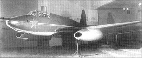
Delta and Shpon veneers bonded by Bakelite – type plastics. The wings had 15-per-cent RAF.34 profile at the root, tapering to 8-per­cent NACA-230 near the pointed tip. In con­trast, the control surfaces were of Dl alloy with fabric covering, the starboard aileron, rudder and both elevators having trim tabs. The rocket engine was a Dushkin/Shtokolov D-1A with a main chamber rated at 1,100kg (2,4251b) at sea level and a cruise chamber rated at 450kg (992 Ib). Under the wings were to have been installed the ramjets, but infor­mation on these Zuyev units is lacking. Their nacelles were to have been oval, with the major axis horizontal, faired neatly into the wing. The all-rocket 302P had tanks for 1,230kg (2,712 Ib) of RFNA (concentrated ni­tric acid) and 505kg (1,113 Ib) of kerosene. The cockpit, which was to have been pres­surized, had a canopy hinged to the right and a bulletproof windscreen and frontal armour. The main and tailwheel landing gears were to have been retracted hydraulically, and the same system would have operated the split flaps. No documents have been found de­scribing how the environmental and hy­draulic systems would have been energised. Two 20mm ShVAK cannon were to have been mounted in the nose and two more in the bottom of the forward fuselage, each with 100 rounds. In addition, there was to have been provision for underwing racks for RS-82 or RS-132 rockets or two FAB-125 bombs.

Top: 302 with PVRD engines. Below: Two views of302.

Kostikov 302, Ko-3


Подпись: Dimensions (302) Span (302) 11.4m 37 ft Min length (excluding guns) 8.708m 28 ft &, in wing area (302) 17.8m2 192ft2
Kostikov 302, Ko-3

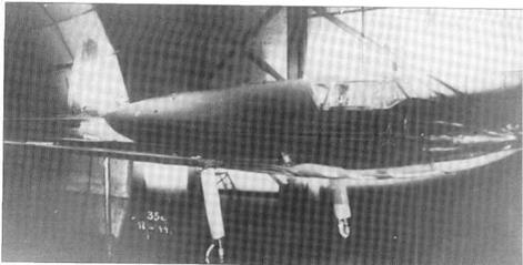
With the benefit of hindsight this appears to 302P in CAHI (TsAGl) wind tunnel. have been a considerable case of ‘might have been’. Kostikov was a political animal who saw in Tikhonravov’s proposal a means to gain advancement and power. Instead, in 1944 a commission headed by A S Yakovlev found him responsible for the failure of the 302 to develop on schedule; he was dis­missed from his post and later imprisoned.

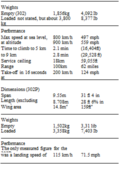
Подпись: Weights Empty (302) 1,856kg 4,092 Ib Loaded not stated, but about 3,800 kg 8,377 Ib Performance Max speed at sea level, 800 km/h 497 mph at altitude 900 km/h 559 mph Time to climb to 5 km 2.1 min (16,404ft) to 9 km 2.8 min (29,528 ft) Service ceiling 18km 59,055ft Range 100km 62 miles Take-off in 16 seconds at 200 km/h 124 mph Dimensions (302P) Span 9.55m 31 fl 4 in Length (excluding guns) 8.708m 28 ft 6% in Wing area 14.8m2 159ft2 Weights Empty 1,502kg 3,31 lib Loaded 3,358kg 7,403 Ib Performance The only measured figure for the 302P was a landing speed of 115 km/h 71.5 mph 302P

Kostikov 302, Ko-3

Kostikov 302, Ko-3

Below: 302P inboard profile.


Above: 302 with PVRD engines.


Kostikov 302, Ko-3

MiG-17 Experimental Versions

Design Bureau: OKB-155 ofAI Mikoyan.

Throughout 1949 the MiG OKB was busy cre­ating the SI, the prototype of a MiG-15 deriva­tive incorporating numerous improvements. Most of these were aerodynamic, including a completely redesigned wing, a horizontal tail of increased sweep on an extended rear fuse­lage, and improved flight controls. The first flight article, SI-2, was flown on 13th January 1950, and on 1st September 1951 MAP Order No 851 required the SI to be put into produc­tion as the MiG-17. Because of the sheer mo­mentum of MiG-15 production the improved aircraft did not replace it in the factories until October 1952. The following specification refers to the MJG-17F, by far the most impor­tant version, which was powered by the af­terburning VK-1F, with a maximum rating of 3,380kg (7,451 Ib).

Dimensions Span Length Wing area

9.628 m 11.26m 22.64 m2

31 ft 7 in 36 ft 1 Min 243.7 ft2

Weights

Empty

3,940kg

8,686 Ib

Fuel/oil

1,170kg

2,579 Ib

Loaded (clean)

5,340kg

1 1,772 Ib

(maximum)

6,069 kg

13,380 Ib

Performance Maximum speed

at sea level

l,100km/h

684 mph

at 3,000m (9,842 ft)

l,145km/h

71 1.5 mph

Mach limit

(clean over 7,000m)

1.15

22,966ft

Time to climb (afterburner)

to 5,000 m

l. Smin

16,404ft

to 10,000m

3.7 min

32,808ft

Service ceiling

(still climbing 3.6 m/s)

16,600m

54,462 ft

Range (clean)

1,160km

721 miles

(maximum)

1,940km

1,205 miles

Take-off speed/

235km/h

146 mph

run

590m

1,936ft

Landing speed/

180km/h

112 mph

run

850m

2,789 ft

SN

In late 1953 the MiG Factory 155 produced an experimental fighter representing the next stage beyond the SU. This time the entire for­ward fuselage was redesigned to house the pivoted guns, the engine being fed by lateral inlets and ducts passing both above and below the wing torsion box (which was given front and rear fairings). Ahead of Frame 13 the entire nose was occupied by the SV-25 ar­mament installation devised by the TKB (Tula design bureau) of Afanas’yev and Makarov. This was based on a large frame mounted on needle-roller bearings on each side and piv­oted on a transverse axis over the range +27° 267-9° 28′ (not 9° 48′ as previously pub­lished). On this frame were mounted three TKB-495 lightweight 23mm guns, fed by box magazines mounted on the fixed structure. The whole installation weighed 469kg (l,0341b), requiring a balancing increase in the size of Tank 3 in the rear fuselage. As this

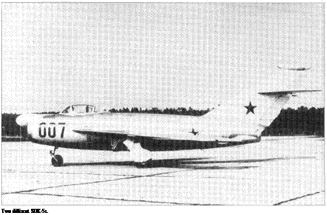
MiG-17 Experimental VersionsПодпись: Two different SDK-5s. Подпись:MiG-17 Experimental Versions

aircraft was so non-standard anyway the OKB took the opportunity to try a few other changes. Of course a special gunsight was needed, and it may have been to improve the optics that a new windscreen was designed, wider and longer than before and giving a bet­ter field of view ahead. The SN was factory – tested by Georgiy K Mosolov from mid-1953. It proved a failure, with seriously reduced flight performance and useless armament. Because the guns were so far ahead of the centre of gravity and centre of pressure of the aircraft, firing them at large angles from the horizontal caused powerfulpitchingmoments which threw the aim off-target. Mikoyan de­cided the problem was not readily soluble. Numerous otherwise unmodified MiG-17s were also used as armament test-beds.

SI-10

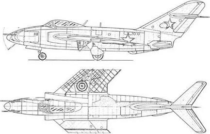
This MiG-17 was one of the original type with the non-afterburning VK-1A engine, with call­sign 214. Having studied the wing and tail of the F-86E Sabre, this aircraft was fitted with important aerodynamic and control changes. The wing was fitted with large automatic slats over the outer 76 per cent of each leading edge, large area-increasing (Fowler-type) flaps, and spoilers (called interceptors) under the outer wings which opened whenever the adjacent aileron was deflected more than 6°. In addition, a fully powered irreversible tailplane was fitted, with limits of +37-5°, re­taining the elevators driven by a linkage to add camber. Grigorii A Sedov flew No 214 on 27th November 1954, followed by many other OKB and NIl-WS pilots. Opinions were favourable, especially regarding the horizon­tal tail, but it was not worth disrupting MiG-17 production to incorporate the changes.

NIAI RK, LIG-7

Purpose: To evaluate an aeroplane with a wing of variable area.

Design Bureau: NIAI, Leningrad.

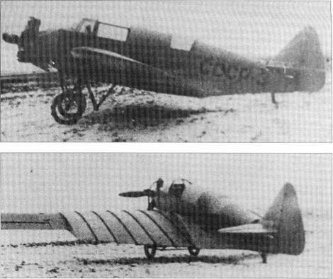
In 1936 Grigorii (according to Shavrov, Georgii) Ivanovich Bakshayev, aged 18, joined the UK GVF, the instructional combine of the civil air fleet. He was eager to test his belief that a su­perior aeroplane could be created by arrang­ing for it to have a large wing for take-off and landing and a smaller wing for cruise. As the UK GVF was in Leningrad the NIAI adopted the idea. Called RK (Razdvizhnoye Krylo, ex­tending wing), and also LIG-7 because it was the seventh project of the Leningrad Institute GVF, the aircraft was built quickly and was first flown in August 1937. Remarkably, the
system worked smoothly and reliably (better in the air than on the ground), and it led to the evenmore unconventional RK-I fighter.

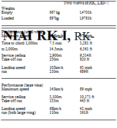
Apart from the wing the RK was a simple monoplane of mixed construction, with en­closed cockpits for a pilot and observer and powered by an uncowled l00hp M-l 1 engine driving a laminated-wood propeller. It had a two-spar wing of constant narrow-chord M-6 profile, braced by pairs of wires above and below to the top of the pilot’s hood and to a pyramid truss under the fuselage. At the root was what looked like the root section of a much larger wing, with CAHI (TsAGI)-846 aerofoil profile, but with a span of only 50cm (1ft 7%in). Inside this, nestling tightly like a set of Russian Matroshka dolls, were five further
plywood wing sections each of 50cm span. The observer could crank these out by a cable mechanism, each adding 45cm (1ft 5%in) to the span of the large-chord region. It took 30 to 40 seconds to crank the telescopic sections out to their full extent, covering 60 per cent of the semi-span, and 25 to 30 seconds to wind them back.

Seemingly a ‘crackpot’ idea, the RK per­formed even better than prediction. It is diffi­cult to account for the fact that it got nowhere. The answer must be that it introduced an el­ement of complexity and possible serious danger, sufficient to dissuade any later de­signer from following suit.

NIAI RK, LIG-7
NIAI RK, LIG-7

Purpose: To create a fighter with variable wing area.

Design Bureau: NIAI, Leningrad.

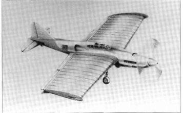
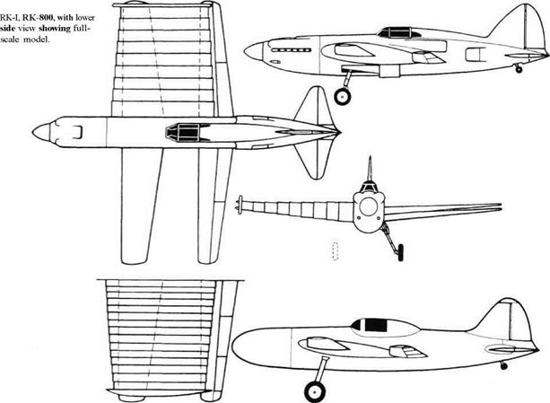
From the start of his telescopic-wing studies young Bakshayev had really been thinking about fighters. He had regarded the RK mere­ly as a preliminary proof-of-concept exercise. He calculated that a fighter able to retract most of its wing area and powered by the M – 105 engine ought to be able to reach a world – record 800km/h (497mph), overlooking the fact that a fighter with a relatively small wing would have poor combat manoeuvrability. Indeed, as described below, he found a way to make the relative difference between the small and large wings even greater than in the RK, the ratio of areas being 2.35:1. In October 1938 he submitted a preliminary design sketch for the RK-I (Russian abbreviation for extending-wing fighter). After much argu­ment the concept was accepted by CAHI (TsAGI) and the WS. A one-fifth-scale model was tested in a CAHI (TsAGI) tunnel from Jan­uary 1939, but it was difficult to find an indus­trial base capable of building even the prototype. Worse, the RK-I attracted the at­tention of Stalin, who took a keen interest in combat aircraft. Excited, he demanded that this aircraft should use the M-106 engine, the most powerful then on bench test. Under
some difficulty a prototype RK-I was com­pleted in early 1940, but the M-106 engine (later designated VK-106) was still far from ready. The aircraft could have flown with the M-105, but nobody dared to fit anything but the engine decreed by Stalin. In order to do at least some testing a full-scale model was con­structed with the nose faired off, fixed landing gears and a projecting canopy, with no at­tempt to simulate armament or the radiator ducts in the rear fuselage. This mock-up was then tested in the CAHI (TsAGI) full-scale tun­nel. The resulting test report was generally favourable, but noted that sealing between the telescopic wing sections was inadequate. The CAHI (TsAGI) aerodynamicists neverthe­less concluded that with the M-106 the speed might be 780km/h (485mph). Lacking an en­gine the project came to a halt, and after the German invasion in June 1941 it was aban­doned. Bakshayev was appointed to super­vise increased production of the 156km/h (97mph) U-2 (Po-2) at Factory No 387.

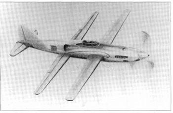
The lifting surfaces of the RK-I were unique, and quite unlike anything attempted by any other designer. The aircraft was all-metal, the large fuselage being a light-alloy monocoque which would have housed the 1,800hp M-106 in the nose with the oil cooler underneath and surrounded by two 20mm ShVAK can­non and two 7.62mm ShKAS machine guns.

Behind the firewall were successively the fuel tanks, backwards-retracting single-strut main landing gears, enclosed cockpit and the gly­col coolant radiator with controllable air ducts on each side of the rear fuselage. The amazing feature was that there were two wings of equal span and narrow tapering chord, one in front of the cockpit and the sec­ond, set at a slightly lower level, behind. Each had upper and lower skins of spot-welded SOKhGSA stainless steel, and the rear wing was fitted with three hinged trailing-edge sur­faces on each side serving as flaps and ailerons. These movable surfaces, like the tail, were made of light alloy. The unique fea­ture was that on this aircraft the root of the large wing extended completely around the front wing and back almost to mid-chord of the rear wing. Nested inside it were 14 further wing profiles, which in 14 seconds could be winched out over the entire span by an elec­tric motor and cable track along the rear wing leading edge, which was at right angles to the longitudinal axis. Each section of the large wing comprised a Dural leading edge and rib with a fabric skin, the first section sealing the side of the fuselage in the high-speed condi­tion and serving as a wing end-plate in the ex­tended low-speed configuration. Shavrov gives the weight of all 28 telescopic sections as approximately 330kg (727.5 Ib). Changing

RK-800


to the large-area configuration was intended to have no significant effect on the rod-oper­ated flight controls, a fact confirmed by CAHI (TsAGI). Bakshayev left drawings showing that a production aircraft would have had only nine larger telescopic sections, and vari­ous other changes.

Had an M-106 engine been available this aircraft might have flown. Pilots would then have been able to assess whether (as seems doubtful) the ability to fly with much less wing


Dimensions

Span

Length

Wing area (large) (small)


area than needed for take-off and landing really offered any advantage to an aircraft designed to engage in close combat.


8.2m

26 ft 10s/, in

8.8m

28 ft 1014 in

28.0m2

301 H2

11.9m2

128ft2

not recorded

3,100kg

6,834 Ib


Weights

Empty

Loaded (estimate)


Performance (estimated)

Max speed (small wings) 780 km/h 485 mph

Endurance 2 hrs 27 min

Landing speed (large wing) 115 km/h 7 1.5 mph


Sketches of RK-I showing its two configurations.

NIAI RK, LIG-7


NIAI RK, LIG-7NIAI RK, LIG-7

Sukhoi T-49

Подпись: Dimensions (Broadlysimilarto PT-7) Length 19.8m 64 ft m in No other data. Sukhoi T-49

Purpose: To create a further-improved interceptor.

Design Bureau: OKB-51 ofP O Sukhoi, Moscow.

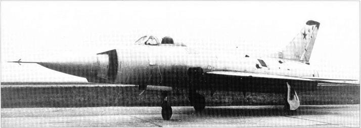
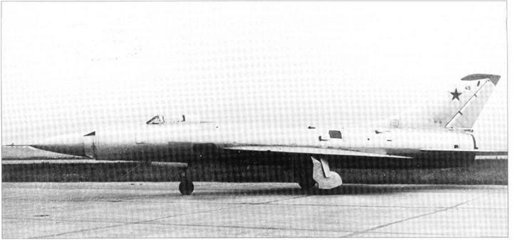
In May 1958 the OKB-51 decided that, after more than four years of effort, they had still not found the best answer to the problem of how to arrange the radar, air inlet(s) and ar­mament of a single-engined supersonic inter­ceptor. It was recognized that guided missiles would be carried externally, probably under the wings, leaving the nose free for radar, but the engine inlet still posed a problem. The PT-8 and T-47 had large radars centred in a nose inlet, and this was considered to de­grade the aerodynamics. Accordingly a new arrangement was devised, and the OKB con­veniently were able to graft it on to the in­complete T-39 (T-3 derivative). The result
thus received the designation T-49. By June 1958 work on the T-39 had been stopped, and this project was transferred as a test-bed to the Central Institute of Aviation Motors. Conversion to the T-49 was completed by Oc­tober 1958. In 1959 M Goncharov was ap­pointed to supervise flight testing, but the T-49 remained on the ground – much of the time being used for various tests – until in January 1960 it was flown by Anatoly Koznov. He re­ported outstanding acceleration and good all­round performance, but by this time aircraft in this class had been overtaken by later tech­nology. In April 1960 the T-49 was damaged in an inflight accident, and though it was re­paired it never flew again.

The T-49 was by virtue of its ancestry very similar to the simpler versions of T-4 family aircraft such as the production Su-9. Like that aircraft it was intended to be armed with two
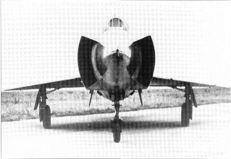
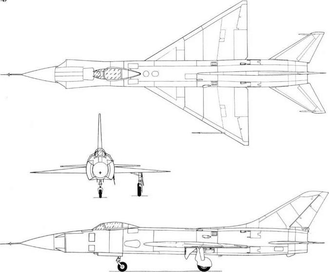
guided missiles carried on pylons under the outer wings, but these would have been of the K-8 type as carried by the Su-11. The large fixed radome was uncompromised by the in­lets, which were located well back on each side. In side elevation each inlet was vertical, seen from the front it formed a 90° segment curved round the side of the fuselage, and in plan it was swept back at 60°. To match pres­sure recovery over the whole range of flight Mach numbers the inner wall was made vari­able in angle and throat area. The intention was to make the whole inlet system isentrop – ic (causing no change in entropy) to achieve maximum compression of the airflow. Like several other Sukhoi designs of the period there were two vertical doors in each side of the fuselage at Frame 7 to spill excess air from the ducts. The engine was a Lyul’ka AL-7F-100, with a dry rating of 6,900kg (15,212 Ib) and maximum afterburning thrust of 9,900kg (21,82515). This was achieved without the need for the injection of water, the T-39’s rear-fuselage water tank being re­placed by one for fuel. Other features includ­ed steel doubler plates left over from the T-39 near where gun muzzles would have been had they been fitted, tailplanes fitted with anti-flutter masses and driven over the ex­ceptional angular range +97-16°, and flaps whose trailing-edge roots were cut away at 45°, which was also a feature of the pro­duction Su-11.

This promising aircraft was overtaken by galloping technology.

This page and opposite top: Three views of T-49.

Sukhoi T-49


Sukhoi T-49

Sukhoi T-49

Tupolev Tu-4 Experimental Versions

Purpose: To use Tu-4 aircraft for various experimental purposes.

Design Bureau: OKB-156 of A N Tupolev.

In The Great Patriotic War the Soviet Union had no modern strategic bomber. Stalin cast covetous eyes on the Boeing B-29, and told Tupolev and Myasishchev to design aircraft in the same class. However, in 1944 three intact B-29s fell into Soviet hands and it was decid­ed just to copy them. Tupolev was given two years to do this immense task. The first air­craft to appear was the Tu-70 transport, which actually used the wing, engines and pro­pellers of one of the B-29s. The production bomber was designated Tu-4, and had Soviet ASh-73TK engines of2,400hp (more powerful than the B-29 engine) and a totally new defensive system with guns of 12.7mm (1st Series), 20mm (from the 8th Series) or 23mm calibre (from the 15th Series). Total produc­tion was close to 1,000. Several Tu-4 aircraft were used in air-refuelling experiments.

The Tu-4T was a single unpressurized trans­port conversion which initially was used for trials with 28 paratroops. In 1954 a small number
of 52-seat versions, again called Tu-4T, were built for the VTA (military transport aviation).

Several Tu-4K conversions were used as carrier aircraft for trials with the Mikoyan KS-1 cruise missile, for use chiefly against ships. This 3 tonne (6,614 Ib) turb ojet-engined weapon was a miniature swept-wing aero­plane with radar guidance (see page 101). The Tu-4K played a major role in the devel­opment of the entire Kompleks (electronic system) which after being cleared for pro­duction was installed in the Tu-16KS, which was the operational carrier of these missiles. Several Tu-4s were used for trials with other missiles, the earliest being with captured FilOS (so-called V-l) pulsejet cruise missiles captured in 1944-45. From March 1945 the Soviet X-10 (Kh-10) copy was on test, and numerous examples were launched from ground ramps and from Tu-2, Yer-2 and Pe-8 aircraft. In 1947 the Tu-4 became available, and several were used to test the 14Kh-l and twin-engined 16Kh, but all this work petered out by July 1955 and none of these missiles entered service.

At least 12 Tu-4s were used as engine test­
beds. Some of the early examples tested tur­boprops, of which the most startling were the three aircraft whose No 3 (starboard inner) engines were replaced by TV-12 turboprops. Take-off power ofthis single-shaft engine was initially ll,995hp, or almost six times that of the engine it replaced. The colossal thrust, which in the Tu-4 could not all be used, was transmitted by a pair of AV-60 co-axial pro­pellers each with four broad blades of 5.6m (18ft 41/2in) diameter. Later this unique pow – erplant was developed into the NK-12M of nearly 15,000hp for the Tu-95 and Tu-142. Other turboprops tested included the ex­Junkers TV-2, Klimov VK-2 (TV-4), Kuznetsov NK-2 and NK-4, and the Ivchenko AI-20, one AI-20 installation (for the Ilyushin 18) having the thrust line and jetpipe above the wing and the other (for the Antonov 10 and 12) having the thrust line and jetpipe below the wing. Jet engines tested under the fuselage of Tu-4LL aircraftincludedtheNene, AL-5,AL-7,7Fand 7P, AM-3 (RD-3), AM-5 and 5F, VD-5, VD-7, VK-2, VK-7 and VK-11.

Tu-4test-bedforNK-12turboprop.

Tupolev Tu-4 Experimental Versions


Bereznyak-Isayev BI

Bereznyak-Isayev BI

Purpose: Experimental rocket-engined interceptor-fighter.

Design Bureau: Designers Aleksandr Yakovlevich Bereznyak and Aleksei Mikhailovich Isayev, working at OKB of Bolkhovitinov, later managed by CAHI (TsAGI).

In 1939 Bereznyak was an observer at the sta­tic tests of the first reliable rocket engine de­veloped by Leonid Stepanovich Dushkin. In early 1940 he watched flight tests of the prim­itive RP-318 (see later under Korolyev). He discussed rocket aircraft with Isayev, who had been a Dushkin engineer involved with the RP-318. In late May 1941 they decided to propose a high-speed rocket-engined fighter. They put the suggestion to Prof Bolkhovitinov (see later entry). After discussion with all in­terested parties Bolkhovitinov sent a letter to GUAP (chief administration ofaviation indus­try) on 9th July 1941 putting forward a de­tailed proposal. Soon a reply came from the Kremlin. The principals were called to GUAP before Shakhurin and A S Yakovlev, and with­in a week there was a full go-ahead. The order was for five prototypes, with the time to first flight cut from the suggested three months to a mere 35 days.

A complete Bolkhovitinov team were con­fined to the OKB for 40 days, working three shifts round the clock. Tunnel testing was
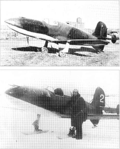
done at CAHI, supervised by G S Byushgens. The first (unpowered) flight article was built without many drawings, dimensions being drawn directly on the materials and on tem­plates. B M Kudrin made the first flight on 10 th September 1941, the tug being a Pe-2. All necessary data were obtained in 15 flights. On 16th October the OKB and factory was evac­uated to a half-built shed outside Sverdlovsk. The first (experimental) D-1A engine was in­stalled in late January 1942, but exploded dur­ing testing on 20th February, injuring Kudrin (sent to hospital in Moscow) and a techni­cian. The replacement pilot was Capt G Ya Bakhshivandzhi. He was in the cockpit on the first tied-down firing on 27th April 1942. On 15th May 1942 he made the world’s first flight of a fully engineered rocket interceptor, still fitted with skis.

By March 1943 seven BI prototypes had been constructed, but the flying was entirely in towed or gliding flight because of serious problems caused by explosions and acid spillages. Powered flying did not resume until February 1943. By this time Kudrin had re­turned to flight status, and was assigned one of the Bis. On powered flight No 6 on 21st March 1943 a height of 3km (9,843ft) was reached in 30 seconds. On powered flight No7, with aircraft No 3, on 27th March, Bakhshivandzhi made a run at sustained full power; the aircraft suddenly pitched over and

dived into the ground. Tunnel testing later showed that at about 900km/h the BI would develop a nose-down pitching moment which could not be held by the pilot.

Dimensions

Span

Nosland2

6.48m

21 ft 3 in

Nos 3 and later

6.6 m

21 ft 8 in

Length

Nos 1 and 2

6.4 m

21ft

Nos 3 and later

6.935 m

22 ft 9 in

Wing area

Nos land 2

7.0m2

75.3ft2

No 3

7.2m2

77.5ft2

Weights

Empty

Nol

462 kg

1,019 Ib

No 3

790kg

1,742Ib

No 7

805kg

l,7751b

Loaded

No 3

1,650kg

3,638 Ib

No 7

1,683kg

3,710 Ib

Performance

Maximum speed

original estimate

800 km/h

497 mph

achieved

900 km/h

559 mph

1943 high-altitude estimate, not attempted

1,020 km/h

634 mph

Time to accelerate from 800 to 900 km/h

20 seconds

Take-off run

400m

1,310ft

Initial climb

120m/s

23,622 ft/min

Time to 5,000 m

50 seconds

16,404ft

Endurance under full power

2 min

Landing speed

143 km/h

89 mph

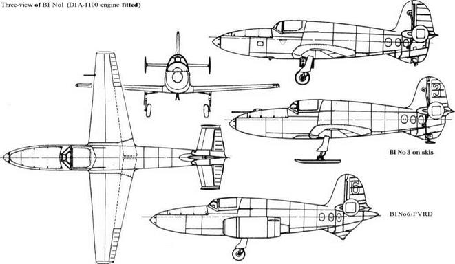
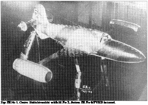
Bereznyak-Isayev BIПодпись: Top: BI No 1. Centre: Bakhchivandzhi with BI No 2. Bottom: BI No 6/PVRD in tunnel. This terminated the delayed plan to build a production series of 50 slightly improved air­craft, but testing of the prototypes continued. Until the end of the War these tested various later Dushkin engines, some with large thrust chambers for take-off and combat and small chambers to prolong the very short cruise en­durance (which was the factor resulting in progressive waning of interest). Other testing attempted to perfect a sealed pressurized cockpit. To extend duration significantly BI No 6 was fitted with a Merkulov DM-4 ramjet on each wingtip. These were fired during test in the CAHI T-101 wind tunnel, but not in flight.
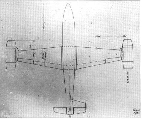
By 1944 the urgency had departed from the programme, and the remaining BI Nol (some were scrapped following acid corrosion) were used as basic research aircraft. BI No7 was modified with revised wing-root fairings and stronger engine cowl panels, but at high speed tailplane flutter was experienced. BI No 5s (on skis) and BI No 6 (on wheels) were modified and subjected to investigative glid­ing tests, initially towed by a B-25J.

In 1948 Bereznyak proposed a mixed – power interceptor with a three-chamber rocket engine of 10,000kg (22,046 Ib) sea – level thrust, for ‘dash’ performance, and a Mikulin AM-5 turbojet of 1,900kg (4,1891b) sea-level thrust. Estimated maximum speed was Mach 1.8, and range 750km (466 miles). This was not proceeded with.

The BI Nol had a small and outstandingly simple all-wood airframe. The straight-ta­pered wing, 6 per cent thick, had two box spars and multiple stringers supporting skin mainly of 2mm ply. Outboard were fabric – covered ailerons. Inboard were split flaps with light-alloy structure (the only major metal parts), with a landing angle of 50°. The fuselage was a plywood monocoque with fabric bonded over the outer surface. It was constructed integral with the upper and lower fins. The rudder and elevators were fabric-covered. On the tailplane were added small circular endplate fins, and the powered aircraft had the tailplane braced to both the upper and lower fins.

The engine bay was lined with refractory materials and stainless steel. The standard engine was the Dushkin D-1A-1100, the des­ignation reflecting the sea-level thrust (2,425 Ib), rising to about 1,300kg (2,866 Ib) at high altitude. The propellants, fed by com­pressed air, were RFNA (red fuming nitric acid) and kerosene. These were contained in cylindrical stainless-steel tanks in the centre fuselage. The pneumatic system not only fed the propellants but also charged the guns and operated the flaps and main landing gears. The latter retracted inwards into the wings and normally had wheels with 500 x 150 tyres. Under the ventral fin was a retracting tail-
wheel. In winter these units were replaced by skis, the main skis retracting to lie snugly under the wings.

The cockpit had a simple aft-sliding canopy, and a bulletproof windscreen. Cer­tain of the prototypes had armament, com­prising two ShVAK 20mm cannon, each with 45 rounds, fired electrically and installed in
the upper half of the nose under a cover se­cured by three latches on each side. Between the spars under the propellant cylinders was a bay which in some aircraft could house a small bomb load (see below). Structural fac­tor of safety was 9, rising to no less than 13.5 after using most of the propellants.

By any yardstick the BI No 1 was a remark­
able achievement, and all pilots who flew it thought it handled beautifully. It was killed by the time it took to overcome the problems, and – crucially – by the impracticably short flight endurance.

The nominal weight breakdown for a fully equipped powered aircraft was:

Airframe

462kg

1,018.5 Ib

Comprising fuselage

182kg

401 Ib

Wing

174kg

383.6 Ib

Tail group

30kg

66 Ib

Landing gear, wheeled

60kg

1321b

Engine

48kg

106 Ib

Controls

16kg

35 Ib

RFNA tanks

80kg

176.4lb

Kerosene tanks

31.2kg

68.8 Ib

Airbottles

22.4kg

49.4 Ib

Guns

84kg

185 Ib

Armour

76 k»

167.5lb

Armour glass, windscreen

6kg

13 Ib

Other equipment about

20kg

44 Ib

Useful load comprised

Pilot

90kg

198 Ib

Nitric acid

570kg

1,256.6 Ib

Kerosene

135kg

297.6 Ib

20mm ammunition

19.6kg

43.2 Ib

Bombs

38.4 kg

84.6 Ib

Bereznyak-Isayev BI

ri

!

OKB drawing of BI No 6/PVRD.

Chetverikov SPL

Purpose: Reconnaissance from submarines. Design Bureau: Brigade of Ivan Vyacheslavovich Chetverikov in CAHI (TsAGI).

Later a famous designer of marine aircraft in his own right, Chetverikov was intrigued by the British submarine M-2, which carried a small aircraft for reconnaissance purposes. Though this proved a disaster in January 1932 when the M-2 was dived with the hangar door open, this did not invalidate the basic con­cept. Funds were obtained from both the MA (naval aviation) and the Glavsevmorput’ (ChiefAdministration ofPolar Aviation N orth – ern Sea Route). Accordingly Chetverikov de­signed a small monoplane in two forms: the OSGA-101 amphibian for Glavsevmorput’ for use from icebreakers and the SPL (Samolyot dlya Povodnikh Lodok, aeroplane for subma­rine boats), a slightly smaller non-amphibious
flying boat able to fold into a small hangar. OSGA flew in spring 1934. The SPL was com­pleted in December 1934, taken by rail to Sev­astopol and flown there by A V Krzhizhevskii in spring 1935. Testing was completed on 29th August 1935. Though the SPL was gener­ally satisfactory, the idea of submarines with aircraft hangars was never adopted by the MA.

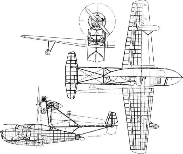
Like its predecessor, the SPL was a neat monoplane, of mainly wooden construction but with the tail made of Dl alloy covered with fabric and carried on booms of welded steel tube through which the control wires passed. The cockpit seated a pilot and ob­server side-by-side, and there was provision for a third seat or cargo immediately to the rear. The engine was a modest M-l 1 rated at l00hp, in a Townend-ring cowl and driving a two-blade wooden propeller. The wings were fitted with plain flaps, and could be un­
locked and manually folded back with the upper surface facing outwards, the under­wing floats also being hinged. The engine na­celle, on a steel-tube pylon, could likewise be pivoted straight back through 90°, so that after four minutes the whole aircraft could be pushed inside a watertight drum 7.45m (24ft 5Kin) long and 2.5m (8ft 21/2in) diameter (in­ternal dimensions).

One report states that the MA claimed the SPL to have ‘inadequate seaworthiness’, while another states that it was difficult to take off from the open sea and was prone to stall because of poor longitudinal stability. The underlying factor was that the MA decid­ed not to build large submarines with SPL hangars.

Chetverikov SPL

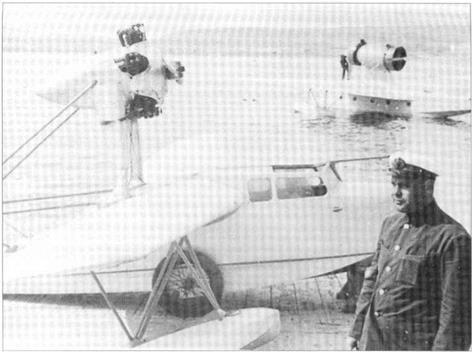
Two views of SPL folded.

Chetverikov SPL


CHETVERIKOV SPL


Dimensions Span Length Wing area

9.5m

7.4m

13.4m2

31 ft 6 in 24 ft 3V. in 144ft2

Weights

Empty

Fuel/oil

Loaded

Maximum

592kg 60+ 10 kg 800kg 879kg

1,30511) 132+2215 l,7641b 1, 9381b

Performance Maximum speed

186 km/h

11 5.6 mph

Cruising speed at 2,500 m

(8,200 ft) 183 km/h

114 mph

Time to climb to 1 ,000 m

3.9 min

(3,280ft)

to 3,000 m

15.3min

(9,843ft)

Service ceiling

5,400m

17,717ft

Range

400km

248 miles

Alightingspeed

85 km/h

53 mph


SPL (the man is not Chetverikov) with ARK-3-2 in background.


Chetverikov SPLChetverikov SPL

Korolyov RP-318-1

Purpose: To test a liquid-propellant rocket engine in flight.

Design Bureau: RNII, rocket-engine scientific research institute; head ofwinged-aircraft department Sergei Pavlovich Korolyov.

Korolyov was a pioneer of light aircraft and, especially, high-performance gliders before, in early 1930s, concentrating on rocketry. In

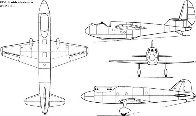
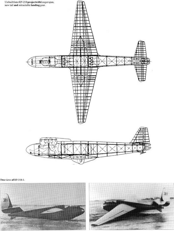
1934 he schemed the RP-218, a high-altitude rocket aircraft with a two-seat pressure cabin and spatted main landing gear. The engines were eventually to have comprised three RD – 1, derived from the ORM-65 (see below), and in a later form the structure was refined and the landing gear made retractable. The RP – 218 was never completed, partly because Ko­rolyov was assigned to assist development of the BICh-11 (see under Cheranovskii). In

1935 he produced his SK-9 two-seat glider, and suggested that this could be a useful rocket test-bed. In 1936, in his absence on other projects, A Ya Shcherbakov and A V Pallo began converting this glider as the flight test-bed for the ORM-65. This was fired 20 times on the bench and nine times in Ko­rolyov’s RP-212 cruise missile before being in­stalled in the RP-318 and fired on the ground from 16th December 1937. The ORM-65 was
then replaced by the RDA-I-150 Nol, cleared to propel a manned aircraft. This engine was repeatedly tested on the ground, and then flew (without being fired) in four towed flights in October 1939. After further tests the RP-318 was towed off on 28th February 1940 by an R-5 flown by Fikson, with Shcherbakov and Pallo as passengers in the R-5. The SK-9 was released at 2,800m, and then glided down to 2,600m where pilot Vladimir Pavlovich Fedorov fired the rocket. The SK-9 accelerated from 80 to 140km/h on the level and then climbed to 2,900m, the engine stop­ping after 110 seconds. Fedorov finally landed on a designated spot. Shavrov: This flight was of great significance for Russia’s rocket en­gines’. Much later Korolyov became the ar­chitect of the vast Soviet space programme.

The RP-318-1 was based on the SK-9, a shapely sailplane of mainly wooden con­struction. The rear seat was replaced by a ver­tical Dl light-alloy tank for 10kg (22 Ib) of kerosene, and immediately behind this were two vertical stainless-steel tanks projecting up between the wing spars each holding 20kg (441b)of RFNA (red fuming nitric acid). The rocket engine and its pressurized gas feed and complex control system were installed in the rear fuselage, the thrust chamber being
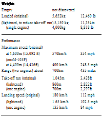
beneath the slightly modified rudder. The RDA-I-150 was a refined version of the ORM – 65, designed jointly by V P Glushko and L S Dushkin. Design thrust was 70 to 140kg at sea level, the figure actually achieved being about 100kg (220.5 Ib). An additional ski was added under the fuselage.

This modest programme appears to have had a major influence on the development of Soviet rocket aircraft.

Dimensions Span Length Wing area

17.0m

7.44m

22.0m2

55 ft 914 in 24 ft 5 in 237ft2

Weights

Empty

570kg

l,2571b

Propellants

75kg

1651b

Loaded

700kg

1, 54315

Performance

Restricted by airframe to

165km/h

102.5 mph

Three-view of unbuilt

Korolyov RP-318-1


Korolyov RP-318-1

SDK-5

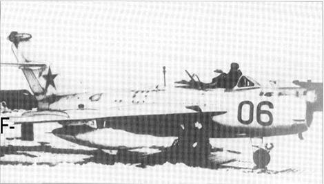
Already used for a MiG-15, this designation was repeated for MiG-17s used for further tests of the guidance system of the KS-1 Komet cruise missile. The original test-bed for this system had been the M1G-9L, and like that aircraft the SDK-5 had forward-facing an­tennas on the nose and wings and an aft-fac­ing antenna above the tail. Like the MiG-9L this aircraft later assisted development of the large supersonic Kh-20 (X-20) missile.

Photograph on the opposite page:

MiG-19 (SM-10).