Purpose: To provide full-scale STOL jet-lift data to support the T6-1.
Design Bureau: OKB-51 of P O Sukhoi, Moscow.
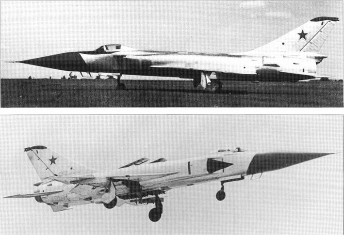
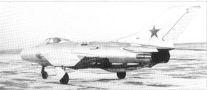
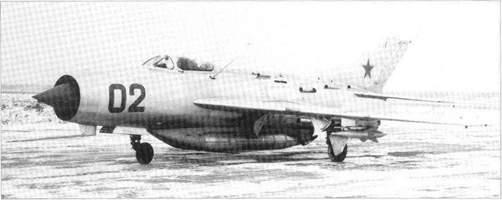
Early history of the T6-1 (see page 178) revolved around how best to create a formidable tactical aircraft with a short field length. One of the obvious known methods of making a STOL (short take-off and landing) aircraft was to fit it with additional jet engines arranged vertically to help lift the aircraft at low speeds. In January 1965 the T-58D-1, the first prototype ofwhat was to become the Su – 15 interceptor, was taken off its normal flight programme and returned to an OKB factory. Here it was modified as the T-58VD, the designation meaning Vertikalnyye Dvigateli, vertical engines. Managed by R Yarmarkov, who had been leading engineer throughout T-58D testing, ground running trials of the VD began in December 1966. This work required an enormous test installation built at the OKB-51 which used a 15,000hp NK-12 turboprop to blast air at various speeds past the T-58VD while it performed at up to full power on all five engines. It was mounted on a special
platform fitted with straingauges to measure the thrust, drag and apparent weight. When these tests were completed, the T-58VD was taken to the LII at Zhukovskii where it began its flight-test programme on 6th June 1966. Initial testing was handled by Yevgenii Solov’yov, who was later joined by the OKB’s Vladimir Ilyushin. On 9th June 1967 this aircraft was flown by Solov’yov at the Domodye – dovo airshow, where NATO called it ‘Flagon-B’. Its basic test programme finished two weeks later. It then briefly tested the ogival (convex curved) radome used on later Su – 15 aircraft and the UPAZ inflight-refuelling pod. It was then transferred to the Moscow Aviation Institute where it was used as an educational aid.
The original T-58D-1 was built as an outstanding interceptor for the IA-PVO air-defence force, with Mach 2.1 speed and armament of K-8M (R-98) missiles. Powered by two R-l 1F2S-300 turbojets (as fitted to the MiG-21 at that time), each with a maximum afterburning rating of 6,175kg (13,6131b), it had pointed delta wings with a leading-edge angle of 60°, fitted with blown flaps. The wings looked very small in comparison with
the fuselage, which had backswept rectangular variable-geometry engine inlets on each side. To convert it into the T-58VD a completely new centre fuselage was spliced in. This used portions of the original air ducts to the main engines but separated them by new centreline bays for three lift jets. The front bay housed a single RD-36-35 turbojet of P A Kolesov design with a thrust of 2,300kg (5,1801b). One of the wing main-spar bulkheads came next, behind which was a bay housing two more RD-36-35 engines in tandem. Each bay was fireproof and fitted with all the support systems shown to be needed in previous jet-lift aircraft. On top were large louvred inlet doors each hinged upward at the rear, while underneath were pilot-controlled cascade vanes for vectoring the lift-jet thrust fore and aft. Another important modification was to redesign the outer wing from just inboard of the fence, reducing the leading-edge sweep to 45° and extending the aileron to terminate just inboard of the new squared-off tip. Apart from the missile pylons
|
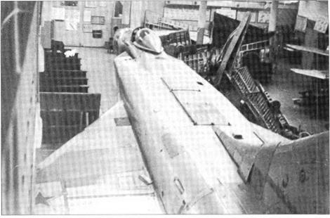
This page and opposite top: Views of T-58VD, one showing its final use at the MAI.
|
|
military equipment was removed, and a new telemetry system was fitted with a distinctive twin-blade antenna under the nose.
 The jet-lift conversion reduced take-off speed and ground run from 390km/h (242mph) and 1,170m (3,839ft) to a less frantic 290km/h (ISOmph) and only 500m (1,640ft). Landing speeds and distances were reduced from 315km/h (196mph) and The jet-lift conversion reduced take-off speed and ground run from 390km/h (242mph) and 1,170m (3,839ft) to a less frantic 290km/h (ISOmph) and only 500m (1,640ft). Landing speeds and distances were reduced from 315km/h (196mph) and
1,000m (3,281ft) to 240km/h (149mph) and 600m (1,969ft). This was achieved at the expense of reduced internal fuel capacity and sharply increased fuel consumption at takeoff and landing. Moreover, it was discovered during initial flight testing that the longitudinal locations of the three lift engines had been miscalculated. Operation of the front RD-36- 35 caused a nose-up pitching moment which the pilot could not counteract at speeds below about 320km/h (199mph), so this lift engine could not be used on landings.

Purpose: To enable a large aircraft to carry one or more small ones long distances, for example to attack targets that would otherwise be out of reach.
Design Bureau: Not an OKB but engineer Vladimir Sergeyevich Vakhmistrov working at the LII (flight research institute).
In 1930 Vakhmistrov suggested that a cheap glider might be used as an aerial gunnery target, and he quickly perfected a way of carrying such a glider above the upper wing of an R-l reconnaissance aircraft and releasing it in flight. This gave Vakhmistrov the idea ofusing a large aircraft to carry a small one on long – range flights over hostile territory. The small aircraft could either be fighters to protect a large bomber, or bomb-carrying attack aircraft or camera-carrying fast reconnaissance aircraft which could make a pass over a target while the parent aircraft stood off at a safe distance. In each case the difficult part was hooking on again for the long flight home. After presenting the WS and LII management with calculations Vakhmistrov received permission to try out his idea. This led to a succession of Zveno (link) combinations:
Z-l
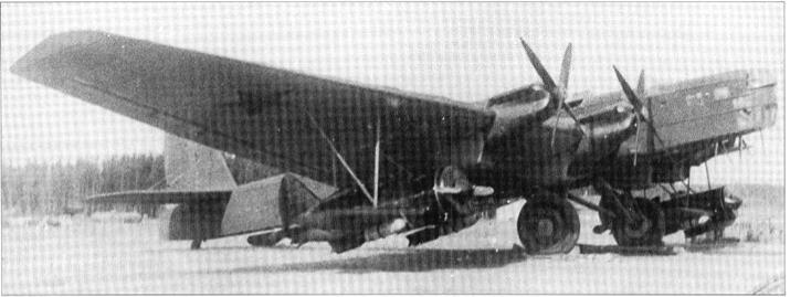
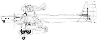
This featured a twin-engined Tupolev TB-1 bomber carrying a Tupolev I-4 fighter above each wing. The fighters were of the I-4Z version, three of which were converted for these experiments with short stub lower wings and attachment locks on the landing gear and under the rear fuselage. The bomber was provided with attachments for the Zveno aircraft above each wing: two small pyramids for the landing gear and a large tripod for the rear – fuselage attachment.
The first flight took place from Monino on 3rd December 1931. The TB-1 was flown by AI Zalevskii and A R Sharapov, with Vakhmistrov as observer. The fighters, with ski landing gears, were flown by V P Chkalov and A S Anisimov. The take-off was made with the fighter engines at full power. The TB-1 copilot forgot the release sequence and released Chkalov’s axle before releasing the aft attachment, but Chkalov reacted instantly and released the rear lock as the fighter reared nose-up. The second fighter was released correctly. For a few seconds the TB-1 flew with no tendency to roll with an I-4Z on one wing.
Z-la
First flown in September 1933, this comprised the TB-1 carrying two Polikarpov I-5 fighters. The latter were fitted with a reinforcing plate under the rear fuselage carrying the rear holddown, but had no special designation. The pilots were P M Stefanovskii (TB-1) and I F Grodz’ and V K Kokkinaki (I-5).
Z-2
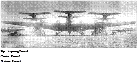
This was the first of the more ambitious hookups using a TB-3 as parent aircraft. The bomber was an early TB-3/4 M-l 7, and it was given attachments for an I-5 above each wing and a third above the fuselage with its wheels on a special flat platform. On the first test in August 1934 the TB-3 was flown by Zalevskii and the fighters by T P Suzi, S P Suprun and T T Al’tnov.
Z-3
This combination would have hung a Grig – orovich I-Z monoplane fighter under each wing of the TB-3. It was not flown.
Z-4
No information.
|
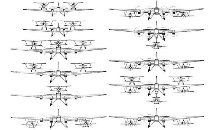
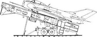
The complete sequence of Zveno developments (not all were tried).
|
|
      Z-5 Z-5
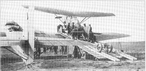
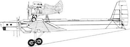
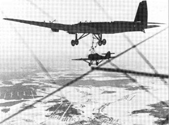
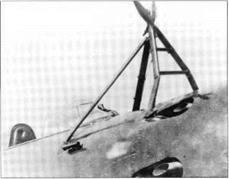
This was the first attempt to hook back on. The parent aircraft was again the TB-3/4 M-l 7, and the fighter was an I-Z fitted with a large suspension superstructure of steel tubes, plus a curved upper guide rail terminating in a sprung hook releasable by the pilot (almost identical to the arrangement used on the airship-borne US Navy F9C Sparrowhawks). This was designed to hook on a large steel-tube trapeze under the bomber, which was folded up for take-off and landing. V A Stepanchy- onok flew the I-Z on several tests with the bomber flown as straight and level as possible by Stefanovskii. The first hook-on took place on 23rd March 1935; this was a world first.
Z-6
The final combination of the original series was the mating oftwo I-16 monoplane fighters hung under the wings ofthe TB-3. The fighters were provided with local reinforcement above the wings to enable them to be hung from sliding horizontal spigots on large tripod links of streamlined light-alloy tube pin-jointed to the bomber’s wing structure. Bracing struts linked the bomber to a latch above the fighter’s rear fuselage, and one ofthe fighters (M-25A-engined No 0440) was photographed with a lightweight pylon above the forward fuselage to pick up under the bomber’s wing. The first test took place in August 1935; Ste – fanovskii flew the TB-3 and the fighter pilots were K K Budakov and AI Nikashin.
Aviamatka
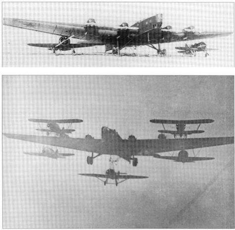
Named ‘mother aircraft’, this amazing test, not part of the original plan, took place in November 1935. The TB-3/4M-17 took off from Monino with an I-5 above each wing and an I-16 below each wing. At altitude it folded down the under-fuselage trapeze and Stepan – chenok hooked on the I-Z, making a combination of six aircraft of four types all locked together. After several passes all the fighters released simultaneously. By this time Vakhmistrov had schemes for up to eight fighters of later types all to be carried by large aircraft such as the full-scale VS-2 tailless bomber projected by Kalinin. Instead Stalin’s ‘terror’ caused the whole effort to wither, but there were still to be further developments.
SPB (Russian initials for fast dive bomber) This was a special version of the Polikarpov I-16 equipped with a rack to carry an FAB-250 (bomb of 250kg, 551 Ib) under each wing. Such an aircraft could not have safely taken off from the ground. In 1937 a later TB-3/4AM – 34RN was made available, and two SPB aircraft were hung under its wings. The first test took place on 12th July 1937, the TB-3 being flown by Stefanovskii and the dive bombers by A S Nikolayev and IA Taborovskii.
Z-7
In November 1939 one final combination was flown: the TB-3/4AM-34RN took off with an I – 16 under each wing and a third hooked under the fuselage in flight (with severe difficulty). The I-16 pilots were Stefanovskii, Nyukhtikov and Suprun.
In early 1940 the WS decided to form a Zveno combat unit. Based at Yevpatoriya, this was equipped with six modified TB-3/4AM – 34RN and 12 SPB dive bombers. During the Great Patriotic War a famous mission was flown on 25 th August 1941 which destroyed the Danube bridge at Chernovody in Romania, on the main rail link to Constanta. Surviving SPBs flew missions in the Crimea.

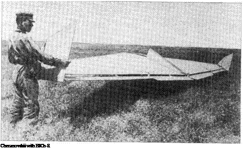
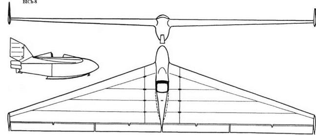
Purpose: To test the use of wingtip rudders. Design Bureau: B I Cheranovskii.
Few details of this machine have survived. It was built and tested in 1929. Cheranovskii was so distressed by the failure of the BICh-7 that he built this simple glider to see ifwingtip rudders could be made to work.
The BICh-8 was dubbed T reoogol’nik (little triangle). It had an open cockpit and centreline skid. The wing was built as a centre section, integral with the nacelle, and outer panels fitted with inboard elevators, outboard ailerons and wingtip rudders with inset hinges mounted on small fins.
This machine may have flown satisfactorily, because Cheranovskii repeated tip rudders in the BICh-11.
No data.
Purpose: Rocket-propelled aircraft for aerodynamic research.
Design Bureau: Ilya Florentyevich Florov (1908-83) had a long career at several OKBs and State organizations, some of his products being biplane fighters designed with A A Borovkov. In 1943 he headed a design cell in NIl-WS (air force state test institute).
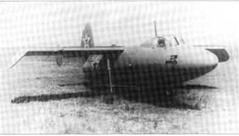
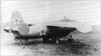
In 1943 Florov was assigned the task of creating a small rocket-engined aircraft to test wing profiles, flight-control systems and other features. At this time published German papers on swept wings (1935) had not been studied. Three examples of No 4302 were funded, and Nil pilots A F Pakhomov and I F Yakubov were assigned to the programme. The No 1 aircraft was not fitted with an engine, and made 46 flights from late 1946, on each occasion being towed to about 5,000m (16,400ft) by a Tu-2. The No 2 was flown under power, the first take-off (by Pakhomov) being in August 1947. In the same month the programme was terminated, funds being transferred to the MiG I-270. At this time the No 3 aircraft had for some time been complete but waiting for its RD-2M-3 engine.
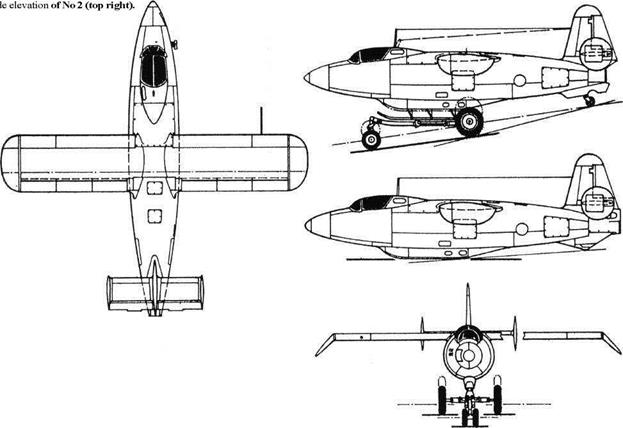
The 4302 was a small aircraft with a fuselage dictated by the size of cockpit and pro
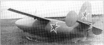
pellant tanks. Construction was entirely light – alloy stressed skin, with a very good surface finish. The untapered wings had a 13-per-cent laminar CAHI (TsAGI) profile devised by G P Svishchev. They were made as one unit attached above the fuselage, with down – turned tips. On each trailing edge were three sections of slotted flap which were also operated in opposition for lateral control. The tail comprised a fixed fin and tailplane, with fixed endplate fins, and manually driven rudder and elevators with inset hinges and mass balances. The pilot had a small pressurized cockpit in the nose with an upward-hinged canopy. The No 1 aircraft was completed with conventional fixed landing gear (using some La-5FN parts), for slow-speed glider flights. The Nos 2 and 3 were designed to take off from a tricycle-gear trolley and land on a centreline skid and tailwheel. The No 2 was fitted with a liquid rocket by A M Isayev assisted by L S Dushkin rated at 1,100kg (2,425 Ib) at sea level. In the rear fuselage was a large tank for red fuming nitric acid made of 3mm Enerzh 18-8 stainless, wrapped with OVS wire to withstand gas feed pressure. Behind was the tank ofpetrol (gasoline). Later, in 1947 a more powerful 1,140kg (2,513 Ib) Dushkin engine was fitted. The No 3 aircraft was to have been
fitted with an RD-2M-3 engine developed by Dushkin and V P Glushko, with main and cruise chambers with sea-level ratings of 1,450 and 400kg (3,197 and 882 Ib). In this condition it was to have been designated No 4303. One report says that an RD-2M or RD – 2M-3 was retrofitted to No 2, but there is no record of it flying with this engine.
These aircraft appear to have left no record of aerodynamic achievement.
|
Dimensions
Span (all) Length (No 2) (No 3)
Wing area (all)
|
6.932m 7.124m 7.152m 8.85 nf
|
22 ft 9 in
23 a VA in 23 ft 5% in 95.26ft2
|
|
Weights
|
|
Empty (No 1)
|
970kg
|
2,138 Ib
|
|
Loaded (No1)
|
1,350kg
|
2,976 Ib
|
|
(No 3)
|
1,750kg
|
3,859 Ib
|
|
Performance
|
|
Max speed (No2, achieved) 826km/h
|
513 mph
|
|
Landing speed (all)
|
125km/h
|
78 mph
|
|
Three-view of 4302 No 3 with
|
|
|
Above left: 4302 Nol.
|
|
 Above right: 4302 No 2 in take-off configuration. Above right: 4302 No 2 in take-off configuration.
Left: 4302 No 2 after landing.
Purpose: To investigate the use of ramjets to boost fighter performance.
Design Bureau: The OKB of Lavochkin, Gorbunov and Gudkov (LaGG).
Unknown to the outside world, the Soviet Union was the pioneer of ramjet propulsion. Such engines are essentially simple ducts, with air rammed in at the front inlet, slowed in an expanding diffuser, mixed with burning
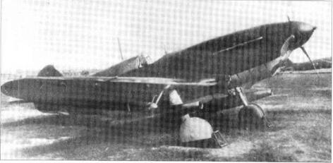
fuel and expelled at high speed through a rear converging section and nozzle. In 1939 M M Bondaryuk, at NIl-GVF OKB-3 (civil air fleet research construction bureau No 3) first ran an experimental subsonic ramjet. In August 1942 a pair of much further developed versions were attached under the wings of LaGG-3 fighter No 31213173 and tested in the air from 5th August. Test pilot Captain Mishenko made 14 flights. Results were indif
ferent, but provided a background of data for later ramjet work, collated by M V Keldysh.
The LaGG-3 was a mass-produced fighter of all-wood construction, powered by an M – 105PF engine. The first Bondaryuk ramjets to fly were designated VRD-1, and were tested in two forms. The original was a plain steel duct with a diameter of 140mm (51/2in), length of 2,150mm (7ft1/2in)and weight of 16kg (35.31b). The boosted (forsirovannyi) version had a diameter of 170mm (6%in) and length of 1,900mm (6ft Sin), but weighed the same. Fuel from the three main aircraft tanks was supplied by a special BNK-10 pump with a proportioner to supply both ramjets equally.
Results were sufficiently interesting to justify further work, starting with the VRD (or PVRD) 430 (see page 89). In parallel Merkulov was developing the DM-4 and similar ramjets, tested on the I-153 and I-207.
Dimensions
Span 9.81 m 32 ft 2 in
Length 8.82 m 28 ft m in
Wing area 17.62m2 189.7ft2
Weight and performance not recorded.
Purpose: To create a supersonic missilearmed all-weather interceptor.
Design Bureau: OKB-155 ofA I Mikoyan
I-3U, I-7U, I-75
In the second half of the 1950s the ‘MiG’ design team created a succession of interceptor fighters which began by reaching 870mph and finished 1,000mph faster than that. The first was the I-1, first flown on 16th February 1955, which resembled a MiG-19 powered by a single large VK-7 centrifugal engine. After a major false start, this led to the I-3U, which (contrary to many reports) was flown in late 1956 on the 8,440kg (18,607 Ib) thrust of a VK- 3 bypass jet (low-ratio turbofan). By this time the aerodynamic shape, and indeed much of the structure and systems, was extraordinarily similar to the contemporary Sukhoi prototypes. The next stage was the I-7U, flown on 22nd April 1957, which used the engine picked earlier by Sukhoi, the excellent Lyul’- ka AL-7F rated at 9,210kg (20,304Ib). In turn this was rebuilt into the I-75, first flown on 28th April 1958. This was the first of the family of impressive MiG single-engined heavy interceptors, with powerful radar (Uragan [hurricane] 5B) and armed only with missiles (two large Bisnovat K-8). A second aircraft was built from scratch, designated I-75F and powered by the uprated AL-7F-1 with a maximum thrust of 9,900kg (21,8251b). The following specification refers to the I-75.
|
Dimensions Span Length Wing area
|
9.976 m 18.275m 31.9m2
|
32 ft 9n in 59 ft 1Г in 343 ft2
|
|
Weights
Empty
|
8,274 kg
|
18,241 Ib
|
|
Internal fuel
|
2,100kg
|
4,630 Ib
|
|
Loaded (clean)
|
10,950kg
|
24,1 40 Ib
|
|
(maximum)
|
11,470kg
|
25,287 Ib
|
|
Performance Maximum speed
clean, at 1 1 ,000 m (36,089 ft) 2,050 km/h
|
1,274 mph (Mach 1.93)
|
|
with missiles
|
1,670 km/h
|
1,038 mph (Mach 1.57)
|
|
Time to climb to 6,000 m (19,685 ft)
|
0.93min
|
|
Service ceiling (Mach 1 .6 in afterburner)
|
1 9, 1 00 m
|
62,664 ft
|
|
Range (internal fuel)
|
1 ,470 km
|
913 miles
|
|
Take-off run
|
1,500m
|
4,921 ft
|
|
Landing speed/run
|
240 km/h
|
149 mph
|
|
with parabrake
|
1,600m
|
5,249ft
|
Ye-150
This was built specifically to test the remarkable R-15 turbojet, created by S KTumanskii, initially working in A A Mikulin’s KB, which he took over in 1956. This engine had been ordered to power future aircraft flying at up to Mach 3 (the first application was a Tupolev cruise missile). The MiG team led by Nikolai Z Matyuk predictably adhered to the proven formula of a tube-like fuselage with a variable multi-shock nose inlet, mid-mounted delta wing (the I-75 had had swept wings) and midmounted swept one-piece tailplanes. This time the fuselage had to accept the R-15-300 engine’s take-off airflow of 144kg (317.51b) per second, and the dry and reheat ratings of this engine were 6,840kg (15,080 Ib) and 10,150kg (22,3771b). At high supersonic Mach numbers the thrust was greatly increased by the ejector – type nozzle, a very advanced propulsion system for the 1950s. As the Ye-150 was not a fighter the cockpit was enclosed by a tiny one – piece canopy of minimum drag. After prolonged delays, mainly caused by the engine, the aircraft was flown by A V Fedotov on 8th July 1960. It required frequent engine replacement, but among other things it reached 2,890km/h (l,796mph, Mach 2.72), climbed to 20km (65,617ft) in 5min 5 sec, and reached a sustained altitude of23,250m (76,280ft).
Ye-152A
This was essentially an interceptor version of the Ye-150, but with the important difference that it was powered by a pair of mature R-l 1F – 300 (early MiG-21 type) engines, with a combined maximum thrust of 11,480kg (25,309 Ib). The airframe was designed to a load factor of 7, and 4,400 litres (968 Imperial gallons) of fuel was provided in six fuselage and two wing tanks, and provision was made for a centreline drop tank. The Ye-152A was designed for almost automatic interceptions, guided by the Uragan-5 ground-control system and its AP-39 autopilot, finally locking on its own T sP-1 radar and firing the two MiG-developed K-9-155 missiles carried on down-sloping underwing pylons. This fine aircraft was first flown by Mosolov on 1 Oth July 1959 (more than a year before the Ye-150) and it reached 2,135km/h (l,327mph, Mach 2.01) at 13,700m (44,950ft). It caused a sensation when it made a flypast at the 1961 Tushino airshow, being identified by Western experts as the (MiG-23′ because that was the next odd number after the MiG-21. After a busy career it crashed in 1965.
Ye-152
This was intended to be the definitive heavy interceptor, combining the R-l5-300 engine (uprated to 10,210kg, 22,509 Ib) with the airframe and weapons of the Ye-152A. Two were built, Ye-152/1 and Ye-152/2. Apart from having a large single engine the obvious new feature was that the Ye-152/1 carried its K-9 missiles on down-sloping launch shoes on the wingtips. Internal fuel was slightly increased, and avionics were augmented. From its first flight on 21st April 1961 it was plagued by engine problems, but eventually set a 100km closed-circuit record at 2,401km/h (1,492 mph, Mach 2.26), a straight-line record at 2,681km/h (l,666mph, Mach 2.52) and a sustained-height record at 22,670m (74,377ft). These were submitted to the FAI as having been set by the ‘Ye-166’. In fact both Mosolov and Ostapenko achieved 3,030km/h (1,883 mph, Mach 2.85). The Ye-152/2 was intended to have the Smerch (whirlwind) radar and associated Volkov K-80 missiles, but this was never incorporated. It first flew on 21st September 1961, and after a brief factory test programme was rebuilt into the Ye-152P.
|
|


 SM-12
SM-12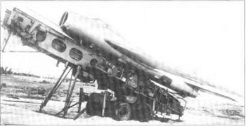



 The jet-lift conversion reduced take-off speed and ground run from 390km/h (242mph) and 1,170m (3,839ft) to a less frantic 290km/h (ISOmph) and only 500m (1,640ft). Landing speeds and distances were reduced from 315km/h (196mph) and


 Z-5
Z-5


 Above right: 4302 No 2 in take-off configuration.