Purpose: To design a long-range supersonic bomber.
Design Bureau: OKB-23 of Vladimir Mikhailovich Myasishchev, Moscow.
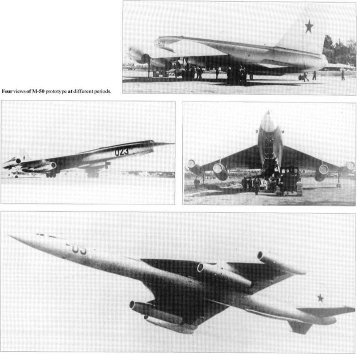
In 1955, when the Myasishchev OKB was still striving to develop the huge 3M subsonic bomber, this design bureau was assigned the additional and much more difficult task of creating a strategic bomber able to make dash attacks at supersonic speed. The need for this had been spurred by the threat of the USAF Weapon System 110, which materialised as the XB-70. The US bomber was designed for Mach 3, but in 1955 this was considered an impossible objective for the Soviet Union. From the outset it was recognized that there could be no question of competing prototypes from different design teams. Even though the Myasishchev OKB was already heavily loaded with completing development of the huge M-4 strategic bomber and redesigning this into the 3M production version, this was the chosen design bureau. In partnership with CAHI (TsAGI), wind tunnels were built for Mach 0.93,3.0 and 6.0. The two partners analysed more than 30
possible configurations, initially in the Izdeliye (product) ’30’ family (VM-32, tailless VM-33 and VM-34). The basic requirement was finally agreed to specify a combat radius not less than 3,000km (1,864 miles) and if possible much more, combined with a dash speed (with engine afterburners in use) of Mach 2. This demanded an upgraded aircraft, and the result was the ’50’ series, starting with the M-50. Under chief designer Georgi Nazarov this was quickly accepted, and the initial programme comprised a static-test specimen and two flight articles, comprising one M-50 followed by an M-52. OKB pilots N I Goryainov and A S Lipko flew the M-50 on 27th October 1959. Modified with afterburning inboard engines, it continued testing in late 1960, but was by this time judged to be of limited value, and to be consuming funds needed for ICBMs (intercontinental ballistic missiles) and space projects. The OKB-23 was closed, and its personnel were transferred to V N Chelomey to work on ICBMs and spacecraft. Myasishchev was appointed Director of CAHI. To the protestations of some, the virtually complete M-52 was scrapped, and six later 50-series projects re
mained on the drawing board. However, for propaganda purposes the M-50 was kept airworthy and made an impressive but rather smoky flypast at the Aviation Day parade at Moscow Tushino on 9th July 1961, naturally causing intense interest in the West. After being photographed with different paint schemes, and the successive radio callsigns 022, 023,12 and 05, it was parked in the nose – high take-off attitude at Monino.
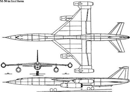
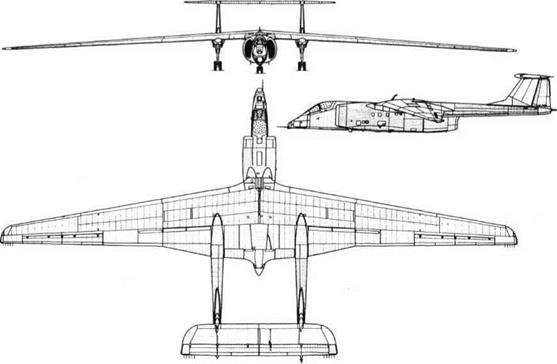
Apart from the totally different wing, in overall configuration, size and weight the M-50 exactly followed the M-4 and 3M family. Despite this every part was totally new, to the last tyre and hydraulic pump. The wing was of pure delta shape, with CAHI R-II profile of only 3.5 to 3.7 per cent thickness, and with a leading-edge angle of 50° from the root to the inboard engines at 55 per cent semi-span, and 41° 30′ from there to the tip. The tip was cropped to provide mountings for the outboard engines. The leading edge was cambered but fixed, while the trailing edge carried rectangular double-slotted flaps and tapered outboard flaperons. At the time this was by far the largest supersonic wing ever flown. Structurally it was based on a
rectangular grid with four transverse spars and seven forged ribs on each side, the skin being formed by forged and machined panels. The enormous fuselage was of almost perfect streamline form, which like the wing was skinned with forged and machined panels. Only a small two-bay section in the nose formed the pressure cabin for the pilot and navigator seated in tandem downward-ejecting seats. These were lowered on cables for the crew to be strapped in at ground level, then winching themselves into place. There was neither a fin nor fixed tailplanes. Instead the tail comprised three surfaces, each with a forward-projecting anti-flutter weight and driven by a quadruple power unit in the twin duplex hydraulic systems. A back-up mechanical control was provided, with rods and levers, but it was expected that this would later be removed. Several possible engines were studied, the finalists being VADo – brynin’s VD-10 and P F Zubts’ 16-17, which was replaced by the 17-18. Construction of the aircraft outpaced both, and in the end the M-50 had to be powered by two Dobrynin VD-7 turbojets on the underwing pylons and two more on the wingtips. As these were temporary they were installed in simple nacelles with plain fixed-geometry inlets. Rated at 9,750kg (21,4951b), these were basically the same engines as those of the 3M. Likewise the main landing gears appeared to be similar to those of the previous bomber, but in fact they were totally new. One of the basic design problems was that the weapons bay had to be long enough to carry the llm (36ft) M-61 cruise missile internally. This forced the rear truck, bearing 63 per cent of the weight, to be quite near the tail, reducing the effective moment arm of the tailplanes and threatening to make it impossible for the pilot to rotate the aircraft on take-off. One answer would have been to use enormous tailplanes, greatly increasing drag, but a better solution was to do what the OKB had pioneered with the M-4 and 3M and equip the steerable front four – wheel landing gear with a double-extension hydraulic strut. Triggered by the airspeed reaching 300km/h (186mph), this forcibly rotated the aircraft 10° nose-up. Another unique feature was that each main gear incorporated a unique steel-shod shoe which, after landing, was hydraulically forced down on to the runway, creating a shower of sparks but producing powerful deceleration, even on snow. For stability on the ground twin-wheel tip protection gears were fitted, retracting forwards immediately inboard of the wingtip engines. All fuel was housed in the fuselage, and yet another unique feature was that to cancel out the powerful change in longitudinal trim caused by the transonic acceleration to supersonic flight fuel was rapidly pumped from Nol tank behind the pressure cabin to No 8 tank in the extreme tail (and pumped back on deceleration to subsonic flight). Over 10 years later the same idea, credited by Myasishchev to L Minkin, was used on Concorde. Flight testing of the M-50 at Zhukovskii was remarkably rapid, though the aircraft proved stubbornly subsonic, stopping at Mach 0.99 even in a shallow dive at full power. In early 1960 the M-50 was modified with afterburning VD-7M engines with a maximum rating of 16,000kg (35,275 Ib) on the inboard pylons and derated VD-7B engines rated at 9,500kg (20,944 Ib) on the wingtips. This was considered to offer the best compromise between available thrust, mission radius and propulsion reliability. The engine installations were redesigned, all four having large secondary cooling airflows served by projecting ram inlets above the nacelle. The outer engines were mounted on extensions to the wing housing new wingtip landing gears which retracted backwards.
The M-52 was under construction from November 1958 and differed in many respects. It was to be powered by four Zubts 17-18 bypass engines each rated at 17,700kg (39,021 Ib). All four were served by efficient variable multishock inlets. The inner engines were ‘set at an angle in relation to the chord line’ and the outers were attached to larger pylons with forward sweep. The nose was redesigned and housed navigation/bombing radar, the crew sat side-by-side, a small horizontal surface was added on top of the rudder, a retractable flight-refuelling probe was added, the interior was rearranged, a remotely controlled barbette was fitted in the tail with twin GSh-23 guns, and provision was made to carry one M-61 internally or four Kh-22 cruise missiles scabbed on semi-externally in pairs conforming to the Area Rule. This aircraft was structurally complete in 1960 but when OKB – 23 was closed it was scrapped.
The M-50 was an extraordinary example of an aircraft which physically and financially was on a huge scale yet which had very limited military value. Not least of the remarkable features of this programme was its relative freedom from technical troubles, even though virtually every part was totally new.
|
Dimensions (M-50 in 1960) Span (over outer engines) Length Wing area
|
35. 1 m 57.48 m 290.6 m2
|
115ft2in 188 ft 7 in 3,128ft2
|
|
Weights
|
|
Empty
|
76,790 kg
|
169,290 Ib
|
|
Normal loaded
|
203,000kg
|
447,531 Ib
|
|
Performance
|
|
Max speed (estimated)
|
1 ,950 km/h
|
1,212 mph (Mach 1.84)
|
|
Cruising spee
|
800 km/h
|
497 mph
|
|
Service ceiling
|
16,500m
|
54,134ft
|
|
Practical range (estimated)
|
7,400 km
|
4,598 miles
|
|
Landing speed (lightweight) 215 km/h
|
133.6 mph
|
|
|
Purpose: To transport outsize cargoes. Design Bureau: EMZ (Eksperimental’nyi Mashinostroitel’nyi Zavod, experimental engineering works) named for V M Myasishchev.
After directing CAHI (TsAGI) from 1960, Myasishchev returned to OKB No 23 in early 1978 in order to study how a 3M strategic bomber might be modified to convey large space launchers and similar payloads. In particular
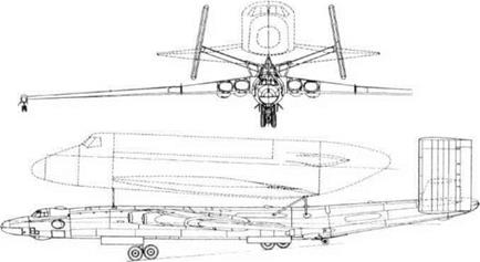
an aircraft was needed to transport to the Baikonur launch site four kinds of load: the nose of the Energiya launcher; the second portion of Energiya; the Energiya tank; and the Buran spacecraft, with vertical tail and engines removed. These loads typically weighed 40 tonnes (88,183 Ib) and had a diameter of 8m (26ft). Myasishchev had previously calculated that such loads could be flown mounted above a modified 3M bomber. He died on 14th October 1978, the programme being continued by V Fedotov. While design went ahead, three 3MN-II tanker aircraft were taken to SibNIA (the Siberian State Research Instiutute named for
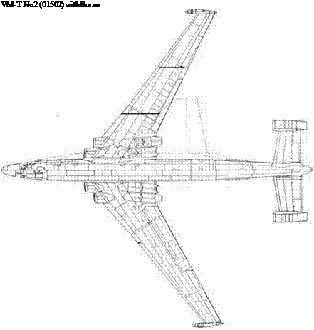
SAChaplygin) and put through a detailed structural audit preparatory to grafting on a new rear fuselage and tail, and mountings for the external payload. The modified aircraft were designated 3M-T. All were rebuilt with zero-life airframes and new engines, but initially without payload attachments. One was static-tested at CAHI while the other two were completed and flown, tne first on 29th April 1981. After a brief flight-test programme they were equipped to carry pick-a-back payloads, and in Myasishchev’s honour redesignated VM-T Atlant. The first flight with a payload was made by AKucherenko and crew on 6th January 1982. Subsequently the two Atlant aircraft carried more than 150 payloads to Baikonur.
The most obvious modification of these air-
craft was that the rear fuselage was replaced by a new structure 7m (23ft) longer and with an upward tilt, carrying a completely new tail. This comprised modified tailplanes and elevators with pronounced dihedral carrying inward-sloping fins and rudders of almost perfectly rectangular shape, with increased total area and outside the turbulent wake
flight-control and autopilot system. The forward fuselage was furnished with work stations for a crew of six. The aircraft were given civilian paint schemes, one being registered RF-01502 and the other being RF-01402 and fitted with a flight-refuelling probe. To support their missions the PKU-50 loading and un
loading facility was constructed at spacecraft factories, including NPO Energiya at Moscow Khimki, and at the Baikonur Cosmodrome. These incorporated a giant gantry for carefully placing the payloads on the carrier aircraft.
Despite the turbulent aerodynamics downstream of the external payloads, this dramat
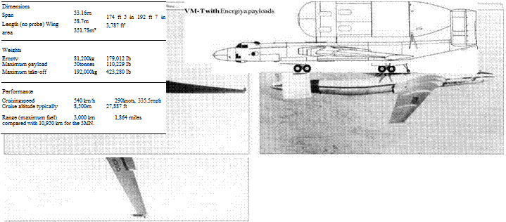
ic reconstruction proved completely successful. In the USA a 747 was used to airlift Shuttle Orbiters, but no other aircraft could have carried the sections of Energiya.
 Purpose: To fly reconnaissance missions at very high altitude.
Design Bureau: EMZ named for V M Myasishchev.
Though not an experimental aircraft, the M-17 qualifies for this book because of its nature, its ancestry, and the fact that it was the basis for the M-55 research aircraft. The concept of manned reconnaissance aircraft penetrating hostile airspace at extreme altitude was com
mon in the Second World War, and in the Cold War reached a flash point on 1st May 1960 when the U-2 ofF G Powers, a CIA pilot, was shot down over Sverdlovsk. One of the American alternatives studied and then actually used was unmanned balloons launched in such a way that prevailing winds would carry them across Soviet territory. They could change altitude, and could carry not only reconnaissance systems but also explosive charges. This threat could have been serious,
 |
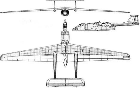 |
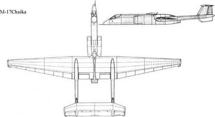
and the PVO (air defence forces) found it difficult to counter. Though still at CAHI, Myasishchev was made head of a secret EMZ tasked with Subject 34, a high-altitude balloon destroyer. Called Chaika (Gull) from its inverted-gull wing, it was to be powered by a single Kolesov RD-36-52 turbojet of 12,000kg (26,4551b) thrust. To reduce jetpipe length the tail was carried on twin booms. In the nose was to be radar and the highly pressurized cockpit, while between the engine inlet ducts was a remotely controlled turret housing a twin-barrel GSh-23 gun. Secretly built at Kumertau helicopter plant in Bashkirya, the Chaika was first flown in December 1978 by K V Chernobrovkin. He had been engaged in taxi tests, and had not meant to take off but in a snowstorm became airborne to avoid hitting the wall of snow on the right side of the runway. In zero visibility he hit a hillside. The programme was relocated at Smolensk, where the second aircraft was constructed to a modified design, designated M-l 7. The first, No 17401, was first flown by E VChePtsov at Zhukovskii on 26th May 1982. It achieved a lift/drag ratio of 30, and between March and May 1990 set 25 international speed/climb/ height records. In 1992 it investigated the ‘hole’ in the ozone layer over the Antarctic. The second M-17, No 17103, was equipped with a different suite of sensors. From the M – 17 was derived the M-55 Geofizka described next.
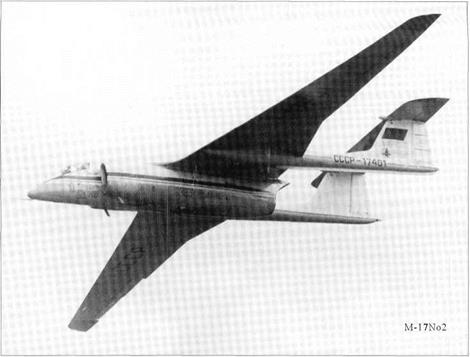 The M-17 had an all-metal stressed-skin structure designed to the low factor of 2. The remarkable wing had an aerofoil of P-173-9 profile and aspect ratio of 11.9, and on the ground it sagged to an anhedral of-2° 30′. The original wing had 16 sections of Fowler flap and short ailerons at the tips, but it was redesigned to have a kinked trailing edge with simplified flaps and longer-span two-part ailerons. Large areas of wing and tail were skinned with honeycomb panels. Flight controls were manually operated, in conjunction with a PK-17 autopilot. The tricycle landing gears retracted hydraulically, the 210kg/cm2 (3,000 lb/in2) system also operating other ser-
vices including three airbrakes above each wing. The engine was an RD-36-51V, with a take-off rating of 12,000kg (26,455 Ib) and nominal thrust of half this value. Cruise thrust at 21,000m (68,898ft) was 600kg (1,32315). T – 8V kerosene was housed in two 2,650 litre main tanks, two 1,550 litre reserve tanks and a 1,600 litre collector tank, a total of 10,000 litres (2,200 Imperial gallons). The pressurized and air-conditioned cockpit housed a
very fully equipped K-36L seat, and among other equipment the pilot wore a VKK-6D suit and VK-3M ventilated suit, and a ZSh-3M protective helmet and KM-32 mask overlain by a GSh-6A pressurized helmet. Avionics were extremely comprehensive.
The M-17 fulfilled all its design objectives. The successive changes in both mission and aircraft design were caused solely by political factors.
 Purpose: To study the ozone layer and perform many other surveillance tasks. Design Bureau: EMZ named for V M Myasishchev, General Designer V K Novikov.
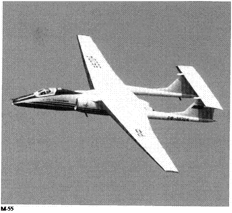
The M-l 7 proved so successful in its basically politico-military role that it was decided in 1985 to produce a derived aircraft specifically tailored to Earth environmental studies. The first M-55, No 01552, was first flown on 16th August 1988, the pilot being Nil Merited Pilot Eduard V Chel’tsov who had carried out the initial testing ofthe M-1 7. Three further examples were built, Nos 55203/4/5. Further single – seaters, plus the M-55UTS dual trainer, the Geofizka-2 two-seat research aircraft and other derived versions, have been shelved through lack of funds.
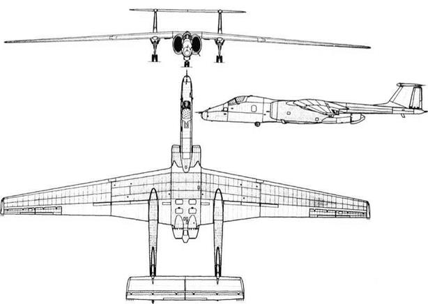 |
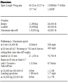
Structurally the M-55 was designed to a load factor increased from 2 to 5. This resulted in a new wing which instead of having left/right panels joined on the centre line has inner and outer panels joined to a centre section. Aspect ratio is reduced to 10.7, and aerodynamically the wing retains the P-173-9 profile but has redesigned flaps, ailerons and upper-surface airbrakes. The horizontal tail is modified, with full-span elevator tabs and square tips. The fuel capacity is increased to
10,375 litres (2,282 Imperial gallons), and range/endurance was further increased by changing to a pair of P A Solov’yov D-30-10V turbofans each rated at 9,500kg (20,944 Ib) take-off thrust, and with a combined cruise thrust at 21km (68,898ft) of 670kg (l,4771b). Apart from the landing gear the aircraft was almost totally redesigned, the front of the nacelle being much deeper and more capacious, the engine bays being lengthened, and the flight controls being operated by a dualchannel digital system with manual reversion. In standard form the M-55 carries a payload of up to 1.5 tonnes (3,307 Ib), typically comprising a Radius scanning radiometer with swath width of 20km (12.4 miles), a
choice ofIR linescanners with swath width of 25km (15.5 miles), an Argos optical scanner with swath width of 28km (17.4 miles), an A-84 optical camera with swath width of 120km (74.6 miles) and a choice of SLARs (sideways-looking airborne radars) with maximum swath width of 50km (starting at 30km and extending to 80km) on each side. Coverage of 100,000km2 (38,610 square miles) per hour is matched to an instrumentation transmission rate of 16 Mbits per second.
The EMZ have created a versatile research and geophysical aircraft which is being promoted for such varied tasks as search/rescue, mapping, ozone studies, hailstorm prevention and agricultural monitoring.
|
Dimensions
|
Span
|
37.46m
|
122 ft 10% in
|
|
Length
|
22.867 m
|
75 ft M in
|
|
Wing area
|
131.6m2
|
1,417ft2
|
|
Weights
|
|
|
|
Empty
|
13,995kg
|
30,853 Ib
|
|
Maximum take offweight
|
23,800kg
|
52,469 Ib
|
|
Performance
|
|
|
|
Maximum speed
|
|
|
|
at 5 km (16,404 ft)
|
332 km/h
|
206 mph
|
|
at 20 km (65,61 7 ft) rising to 750 km/h
|
466 mph
|
|
Practical ceiling 2 1,850m
|
in 35 min
|
(71,686ft)
|
|
Endurance
|
|
|
|
at practical ceiling
|
2hrs 14 min
|
|
|
at a cruise height of 1 7 km
|
6 hrs 30 min
|
(55,774ft)
|
|
Max range on direct flight
|
4,965km
|
3,085 miles
|
|
Take-off/landing
|
Similar to M-17.
|
|
|

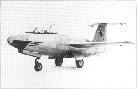
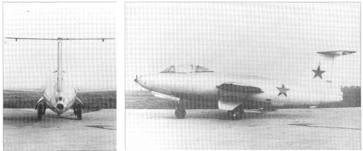
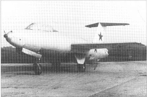


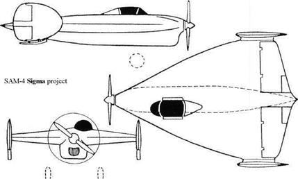
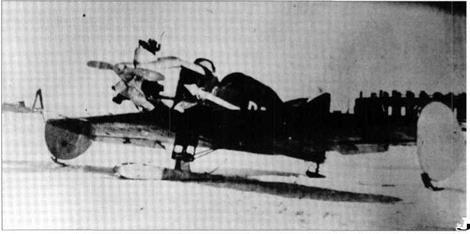
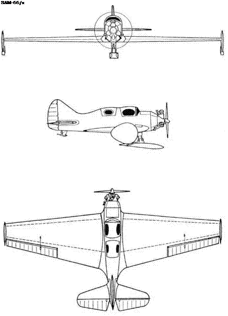 Top right: SAM-6.
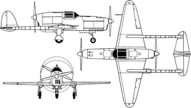
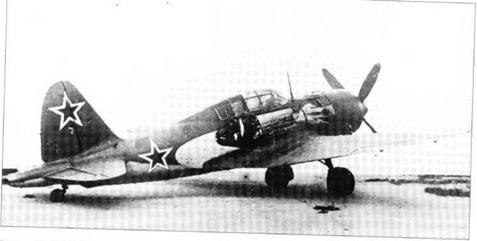
 Purpose: To build a superior two-seat fighter.
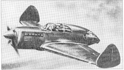
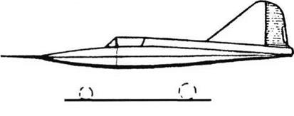
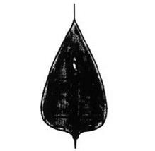
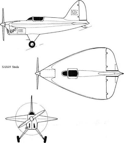 Purpose: To test at modest speeds an aircraft with a ‘Gothic delta’ wing of very low aspect ratio.
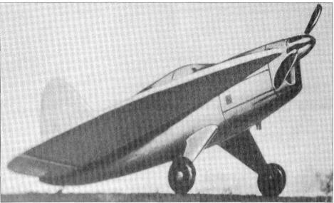
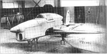


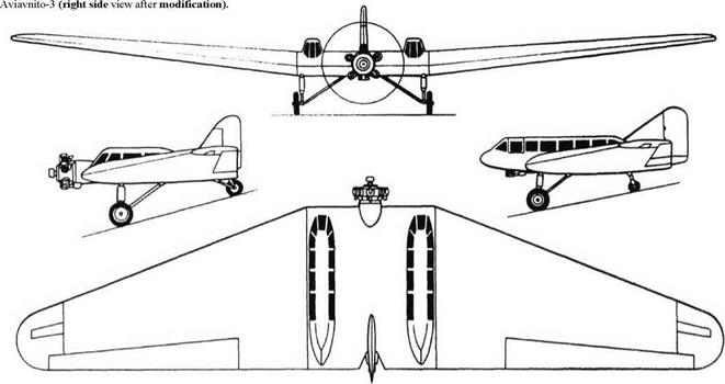
 a trim tab. One account says that the inverted – gull shape ‘improved stability and provided a cushion effect which reduced take-off and landing distance’, but its only real effect was to raise the wing on the centreline from the low to the mid position.





 Purpose: To fly reconnaissance missions at very high altitude.

 The M-17 had an all-metal stressed-skin structure designed to the low factor of 2. The remarkable wing had an aerofoil of P-173-9 profile and aspect ratio of 11.9, and on the ground it sagged to an anhedral of-2° 30′. The original wing had 16 sections of Fowler flap and short ailerons at the tips, but it was redesigned to have a kinked trailing edge with simplified flaps and longer-span two-part ailerons. Large areas of wing and tail were skinned with honeycomb panels. Flight controls were manually operated, in conjunction with a PK-17 autopilot. The tricycle landing gears retracted hydraulically, the 210kg/cm2 (3,000 lb/in2) system also operating other ser-
 Purpose: To study the ozone layer and perform many other surveillance tasks. Design Bureau: EMZ named for V M Myasishchev, General Designer V K Novikov.


