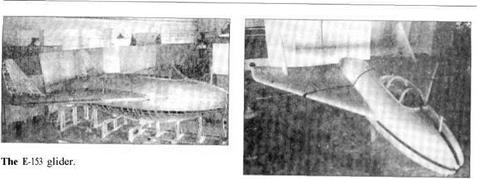
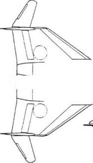
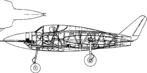
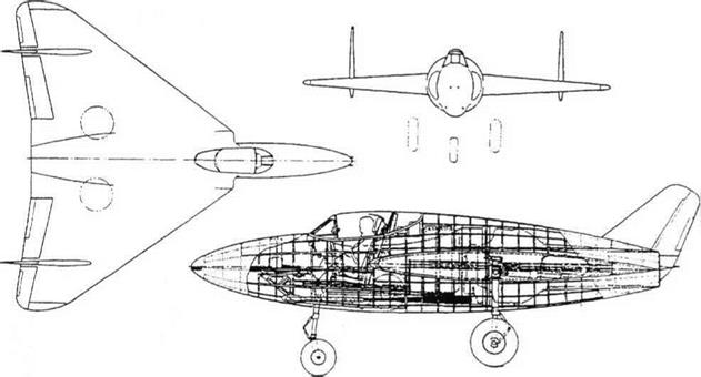
Category Soviet x-plenes

Bartini Stal’-6, El, and StaP 8

Purpose: High-speed research aircraft with fighter-likepossibilities.

Design Bureau: SNII, at Factory No 240.

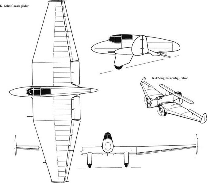
One of the few aircraft designers to emigrate to (not from) the infant Soviet Union was Roberto Lodovico Bartini. A fervent Commu­nist, he chose to leave his native Italy in 1923 when the party was proscribed by Mussolini. By 1930 he was an experienced aircraft de­signer, and qualified pilot, working at the Central Construction Bureau. In April of that year he proposed the creation of the fastest aircraft possible. In the USSR he had always suffered from being ‘foreign’, even though he had taken Soviet citizenship, and nothing was done for 18 months until he managed to en­list the help of P I Baranov, head of the RKKA (Red Army) and M N Tukhachevskii (head of RKKA armament). They went to Y Y Anvel’t, a deputy head at the GUGVF (main directorate of civil aviation), who got Bartini established at the SNII (GVF scientific test institute). Work began here in 1932, the aircraft being desig­nated Stal’ (steel) 6, as one of a series of ex­
perimental aircraft with extensive use ofhigh – tensile steels in their airframes. After suc­cessful design and construction the Stal’-6 was scheduled for pre-flight testing (taxi runs at increasing speed) in the hands of test pilot Andrei Borisovich Yumashev. On the very first run he ‘sensed the lightness of the con­trols., .which virtually begged to be airborne’. He pulled slightly back on the stick and the aircraft took off, long before its scheduled date. The awesomely advanced aircraft proved to be straightforward to fly, but the en­gine cooling system suffered a mechanical fault and the first landing was in a cloud of steam. Yumashev was reprimanded by Barti­ni for not adhering to the programme, but testing continued. Yumashev soon became the first pilot in the USSR to exceed 400km/h, and a few days later a maximum-speed run confirmed 420km/h (261 mph), a national speed record. One of Bartini’s few friends in high places was Georgei K Ordzhonikidze, People’s Commissar for Heavy Industries. In November 1933, soon after the Stal’-6 (by this time called the El, experimental fighter) had
shown what it could do, he personally or­dered Bartini to proceed with a fighter de­rived from it. This, the Stal’-8, was quickly created in a separate workshop at Factory 240, and was thus allocated the Service des­ignation of I-240. Hearing about the Stal’-6’s speed, Tukhachevskii called a meeting at the Main Naval Directorate which was attended by many high-ranking officers, including heads from GUAP (Main Directorate of Avia­tion Production), the WS (air force), RKKA and SNII GVF. The meeting was presided over by Klementi Voroshilov (People’s Commissar for Army and Navy) and Ordzhonikidze. At this time the fastest WS fighter, the I-5, reached 280km/h. The consensus of the meeting was that 400km/h was impossible. Many engineers, including AAMikulin, de­signer of the most powerful Soviet engines, demonstrated or proved that such a speed was not possible. When confronted by the Stal’-6 test results, and Comrade Bartini him­self, the experts were amazed. They called for State Acceptance tests (not previously re­quired on experimental aircraft). These began

Bartini Stal’-6, El, and StaP 8

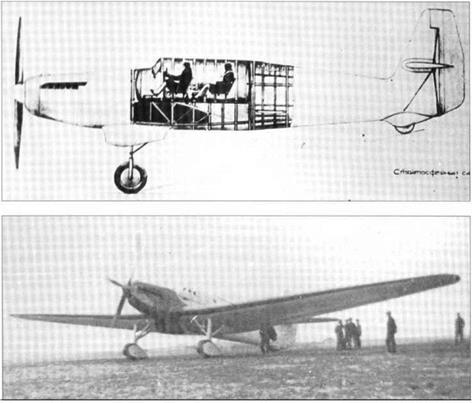
Top: Stal’-6.

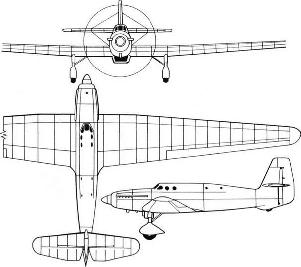
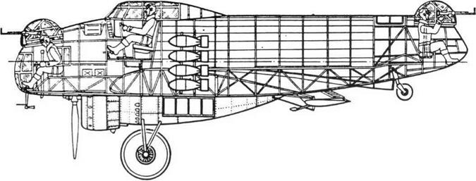
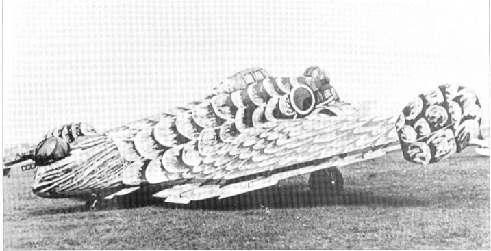
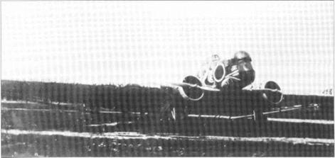
Centre: Three views of the StaP-6. Bottom: Inboard profile of Stal’-6.


Bartini Stal’-6, El, and StaP 8Bartini Stal’-6, El, and StaP 8Bartini Stal’-6, El, and StaP 8

Подпись: Stal'-8 model in tunnel.

in the hands of Pyotr M Stefanovskii on 8th June 1934 (by which time the fast I-16 mono­plane fighter was flying, reaching 359km/h). On 17th June the Stal’-6 was handed to the Nil WS (air force scientific research institute), where it was thoroughly tested by Ste – vanovskiy and N V Ablyazovskiy. They did not exceed 365km/h, because they found that at higher speeds they needed to exert consider­able strength to prevent the aircraft from rolling to port (an easily cured fault). On 13th July the landing-gear indicator lights became faulty and, misled, Stefanovskii landed with the main wheel retracted. The aircraft was re­paired, and the rolling tendency cured. Vari­ous modifications were made to make the speedy machine more practical as a fighter. For example the windscreen was fastened in the up position and the pilot’s seat in the raised position. Aftervarious refinements Ste­fanovskii not only achieved 420km/h but ex­pressed his belief that with a properly tuned engine a speed 25-30km/h higher than this might be reached. The result was that fighter designers – Grigorovich, Polikarpov, Sukhoi and even Bartini himself – were instructed to build fighters much faster than any seen hith­erto. Bartini continued working on the StaP-8, a larger and more practical machine than the Stal’-6, with an enclosed cockpit with a for­ward-sliding hood, two ShKAS machine guns and an advanced stressed-skin airframe. The engine was to be the 860hp Hispano-Suiza HS12Ybrs, with which a speed of 630km/h (391 mph) was calculated. Funds were allo­cated, the Service designation of the Stal’-8 being I-240. This futuristic fighter might have been a valuable addition to the WS, but Bar­tini’s origins were still remembered even in the mid-1930s, and someone managed to get funding for the Stal’-8 withdrawn. One reason put forward was vulnerability of the steam cooling system. In May 1934 the I-240 was abandoned, with the prototype about 60 per cent complete.

Everything possible was done to reduce drag. The cantilever wing had straight taper and slight dihedral (existing drawings incor­rectly show a horizontal upper surface). The two spars were made from KhMA (chrome – molybdenum steel) tubes, each spar com­prising seven tubes of 16.5mm diameter at the root, tapering to three at mid-semi-span and ending as a single tube of 18mm diame­ter towards the tip. The ribs were assembled from Enerzh-6 (stainless) rolled strip. Ailerons, flaps and tail surfaces were assembled from steel pressings, with Percale fabric skin. The flaps were driven manually, and when they were lowered the ailerons drooped 5°. Barti­ni invented an aileron linkage which adjusted stick force according to indicated airspeed (this was resurrected ten years later by the Central Aero-Hydrodynamic Institute as their
own idea). The fuselage was likewise based on a framework of welded KhMA steel tubes. Ahead of the cockpit the covering comprised unstressed panels of magnesium alloy, the aft section being moulded plywood. In flight the cockpit was part-covered by a glazed hood flush with the top of the fuselage, giving the pilot a view to each side only. For take-off and landing the hood could be hinged upwards, while the seat was raised by a winch and cable mechanism. Likewise the landing gear was based on a single wheel on the centre­line, with an 800 x 200mm tyre, mounted on two struts with rubber springing. The pilot could unlock this and raise it into an AMTs (light alloy) box between the rudder pedals. For some reason the fuselage skin on each side of this bay was corrugated. The wheel bay was normally enclosed by a door which during the retraction cycle was first opened to admit the wheel and then closed. Extension was by free-fall, finally assisted by the cable until the unit locked. Under the outer wings were hinged support struts, likewise retract­ed to the rear by cable. When extended, each strut could rotate back on its pivot against a spring. Under the tail was a skid with a rubber shock absorber. The engine was an imported Curtiss Conqueror V-1570 rated at 630hp, dri­ving a two-blade metal propeller with a large spinner (photographs show that at least two different propellers were fitted). This massive vee-12 engine was normally water-cooled, but Bartini boldly adopted a surface-evapora­tion steam cooling system. The water in the engine was allowed to boil, and the steam flowed into the leading edges of the wings which were covered by a double skin from the root to the aileron. Each leading edge was electrically spot – and seam-welded, with a soldering agent, to form a sealed box with a combined internal area of 12.37m2 (133ft2).

Each leading edge was attached to the upper and lower front tubes of the front spar. Inside, the steam, under slight pressure, condensed back into water which was then pumped back to the engine. The system was not de­signed for prolonged running, and certainly not with the aircraft parked.

Bartini succeded brilliantly in constructing the fastest aircraft built at that time in the So­viet Union. At the same time he knew per­fectly well that the Stal’-6 was in no way a practical machine for the WS. The uncon­ventional landing gear appeared to work well, and even the evaporative cooling sys­tem was to be perpetuated in the I-240 fight­er (but that was before the Stal’-6 had flown). Whether the I-240 would have succeded in front-line service is doubtful, but it was the height of folly to cancel it. The following data refers to the Stal’-6.

Dimensions Span Length Wing area

9.46m

6.88m

14.3m2

31 ft 14 in 22 ft 6% in 154ft2

Weights

Empty

850kg

1,874 Ib

Maximum loaded weight

1,080kg

2,381 Ib

Performance

v Maximum speed

420km/h

261 mph

Maximum rate of climb

21m/s

4,135ft/min

Service ceiling

8,000 m

26,250ft

Endurance

1 hour 30 min

Minimum landing speed

llOkm/h

68.4 mph

Stal’-8,I-240

Bartini Stal’-6, El, and StaP 8


BOK-5

Purpose: To experiment with a tailless (so – called ‘flying wing’) design.

Design Bureau: Bureau of Special Design, Smolensk. Design team led by V A Chizhevskii.

The idea for this small research aircraft came from the BOK-2, though the two aircraft were completely unrelated. In 1935 Chizhevskii began studying tailless aircraft, and obtained funding to build a simple research aircraft. This was completed in early 1937, but was then modified and did not fly until Septem­ber, the pilot being I F Petrov. It ‘flew satisfac- torily…but crashed during a landing’. After being repaired and modified its handling qualities were greatly improved. In 1938 the
modified aircraft was tested by the Nil WS (air force flight-test institute), where it was flown by such pilots at P M Stefanovskii and M A Nyukhtikov. Stefanovskii is reported to have said that the BOK-5 could be ‘flown by pilots of average or even below average abil­ity’ and to have been ‘impressed by its acro­batic capability’.

The BOK-5 was a basically simple aircraft, apart from the flight-control system. The air­frame was made of duralumin. The wing was ofCAHI (TsAGI) 890/15 profile (15 per cent t/c ratio), with two spars with tubular booms and sheet webs, and ribs assembled from chan­nel and angle sections, with fabric covering. The short fuselage was a semi-monocoque, with some box-section longerons and
pressed-sheet frames, the vertical tail being integral. The main landing gears were de­scribed as ‘U-2 type’. On the nose was a 1 00hp M-l 1 engine in a Townend-ring cowl, driving a two-blade metal propeller.

Modifications concentrated on the trailing – edge controls. According to Shavrov there were three movable surfaces on each wing, extending over 21 per cent of the chord. The outermost was a rectangular aileron, and the two inboard surfaces acted in unison as ele­vators. Most photographs and drawings show these surfaces as simple one-piece units hinged to brackets below the trailing edge and with a neutral setting of-5°. However, re­cently a drawing (reproduced here) was dis­covered showing the main surfaces operated

BOK-5


BOK-5

BOK-5

by servo action. The pilot’s control cables can be seen to drive a narrow-chord servo control which in turn moves the main surface. The neutral setting of the main surfaces can be seen to be adjusted by a longitudinal-trim wheel with cables to screw-jacks.

The BOK-5 was clearly a safe aircraft which impressed two of the Soviet Union’s best test pilots, but it remained a one-off which was soon forgotten.

Dimensions Span Length Wing area

9.86m

4.365m

23.15m2

32 ft 4Л in 14 ft 4 in

249ft2

Weights

Empty

596kg

1,314 Ib

Fuel

90kg

198 Ib

Loaded

764kg

l,684lb

Performance

Maximum speed

174km/h

108 mph

Take-off run

120m

394ft

Service ceiling

4,850 m

15,900ft

Range

600km

373miles

Endurance

4 hours

Landing speed/

85km/h

53 mph

run

200m

656ft

Top and centre: Two views of BOK-5.

BOK-5BOK-5Bottom: BOK-5 servo control.

Kamov Ka-22

Подпись: Ka-22 (bottom view, record configuration).Kamov Ka-22Kamov Ka-22

Purpose: To create a Vintokryl (screw wing) compound helicopter.

Design Bureau: OKB ofNikolai Kamov, Moscow.

In 1951 various attempts were being made to increase the effective range of helicopters, notably by towing them in the outward direc­tion behind an Li-2, with the lifting rotor au- torotating. The idea occurred to Kamov designer Vladimir Barshevsky that it would be possible to dispense with the tug aircraft if a helicopter could be provided with wings and an aeroplane propulsive system. After obtain­ing permission from Kamov, his deputy V V Nikitin took a proposal to the Kremlin and in a matter of days the OKB had a Stalin di­rective to get started. The engines were to be TV-2 (later TV-2VK) turboshafts supplied by N D Kuznetsov, and many organizations were involved in research for this challenging pro­
ject, starting with model tests in the T-l 01 tun­nel at CAHI. The final go-ahead was issued on 11 th June 1954. An order for three Ka-22s was placed on the factory at Ukhtomskaya, which had been derelict since Kamov was evacuat­ed from there in October 1941. Concentration on the small Ka-15 (the OKB’ sfirstproduction helicopter) and other problems so delayed the programme that on 28th March 1956 pro­totypes 2 and 3 were cancelled. In June 1958 the LD-24 rotor blades began testing on an Mi-4. The Ka-22 itself first lifted from the ground on 17th June 1959, and made its first untethered flight on 15th August 1959, the test crew being led by pilot D K Yefremov. Serious control difficulties were encoun­tered, and the Kamov team were joined by LII pilots VVVinitskii and YuAGarnayev. Though still full of problems the Vintokryl was demonstrated on llth October 1959 to MAP Minister PVDement’yev and WS C-in-C

KAVershinin. Gradually difficulties were solved and in July 1960 an order was received to manufacture three Ka-22s at GAZ No 84 at Tashkent, with D-25VK engines. On 23rd May 1961 a speed of230km/h was held for 37 min­utes. On 9th July 1961 the Ka-22 caused a sen­sation at the Aviation Day at Tushino. On 7 th October 1961, with spats over the wheels and a fairing behind the cockpit, a class speed record was set at 356.3km/h (221.4mph), followed on 12th October by 336.76km/h (209.3mph) round a 100km circuit. The spats and fairing were then removed and on 24th November 1961 a payload of 16,485kg (36,343 Ib) was lifted to 2,557m (8,389ft). Preparations were then made to ferry AM 0I – 01 and the third machine AM 0I-03 from Tashkent to Moscow for Nil acceptance test­ing. Both departed on 28th August 1962. While making an intermediate stop at Dzhusaly 0I-01 rolled to the left and crashed inverted, killing Y efremov and his crew of six. The cause was diagnosed as ‘disconnection of No 24 cable joint of the linkage with the starboard lift rotor collective-pitch control unit’. At Tashkent and in Turkestan the cable joints and cyclic-pitch booster brackets were inspected on 0I-02 and 0I-03 and found to be incorrectly assembled. Changing the direc­tion of rotation of one lifting rotor did little at lower speeds and caused problems at higher speeds – ‘When’, said lead engineer V S Dor – dan, ‘Shockwaves off the blades sounded like a large machine gun’. To improve stability and controllability the complex AP-116 differ­ential autopilot was installed, continuously sensing attitude and angular accelerations, feeding the KAU-60A combined flight-control unit. On 12th August 1964 the heavily instru­mented 0I-03 took off on one of a series of tests conducted with WS (air force) and GVF (civil) crews. Take-off was in aeroplane mode, and 15 minutes later at 310km/h (193mph) the aircraft suddenly turned to the right, ‘not arrested by full rudder and aileron.. .the aircraft turned almost 180° when Garnayev intervened, considering the prob­lem was differential pitch of the pro – pellers…turn rate slowed, but the aircraft pitched into a steep dive…the engineer jetti­soned the flight-deck hatches, and one struck the starboard lift rotor causing asymmetric forces which resulted in separation of the en­tire starboard nacelle. Garnayev ordered the crew to abandon the aircraft’. Three survived, but Col S G Brovtsev, who was flying, and technician A F Rogov, were killed. By this time the Mi-6 heavy helicopter was in wide service, and the Ka-22 was ultimately aban­doned. Several years later the two surviving machines, 0I-02 and 0I-04, were scrapped.

An article about the Ka-22 in Kryl’ya Rodiny (Wings of the Motherland) for November 1992 does not mention the fact that two crashed, which is not widely known even in the former Soviet Union.

The Ka-22 was basically an aeroplane with its engines on the wingtips, with geared dri­ves to both propellers and lifting rotors. The airframe was all light alloy stressed-skin, the high wing having powered ailerons and plain flaps. The fuselage had a glazed nose, three – seat cockpit above the nose and a main cargo area17.9 x 3.1 x 2.8m (58′ 9" x10′ 2" x 9′ 2") for 80 seats or 16.5 tonnes of cargo. The entire nose could swing open to starboard for load­ing bulky items or a vehicle. The original pro­totype was powered by 5,900-shp TV-2VK engines, but these were later replaced by the 5,500-shp D-25VK. These had free turbines geared via a clutch to the main-rotor and via a front drive to the four-blade propeller and a fan blowing air through the oil cooler from a circular inlet above the nacelle. The two free – turbine outputs were interconnected by a 12- part high-speed shaft ‘about 20m long’. The main rotors were larger derivatives of those of the Mi-4. In helicopter mode the propeller drive was declutched and the flaps were fully lowered. Flight control was by differential cyclic and collective pitch. In aeroplane mode the lifting rotors were free to windmill and the aircraft was controlled by the ailerons and tail surfaces. The twin-wheel landing gears were fixed.

Подпись: Above: Ka-22 in speed-record configuration. Below: Two views of Ka-22. Kamov Ka-22Apart from prolonged dissatisfaction with the engines, the problems with the Ka-22 were mechanical complexity, severe losses in the gearboxes and drives and the fact that each lifting rotor blew straight down on top of the wing. Similar charges could be levelled against today’s V-22 Osprey.

Dimensions

Distance between lifting-rotor centres

23.53m

77 11 2% in

Wing area

105m2

1,130ft2

Diameter oflifting rotors,

originally 22.8 m, later

22.5m

73 ft 9% in

Lifting-rotor area (total)

795.2 m2

8,560ft2

Length

27.0 m

88 ft 7 in

Weights

Empty (initially)

25 tonnes

later

28,200 kg

62,169 Ib

Loaded (VTO)

35,500 kg

78,263 Ib

(STO)

42,500kg

93,695 Ib

Performance

Maximum speed

375 km/h

233 mph

Dynamic ceiling (VTO)

5,500 m

18,050ft

(STO)

4,250 m

13,944ft

Potential maximum range

(calculated by Barshevsky) 5,500 km

3,418 miles

STO run

300 m

984ft

Landing over 25m

130m

426.5ft


Kamov Ka-22

MiG I-270, Zh

Purpose: To investigate the potential of a rocket-propelled interceptor.

Design Bureau: OJB-155 ofA I Mikoyan.

As a major (in most respects the greatest) pi­oneer of rocket-propelled aircraft, the Soviet Union was intrigued to capture examples of the Messerschmitt Me 163 and Me 263 (Ju248). In 1944the MiG OKB produced ‘doo­dles’ of Me 163 type aircraft, but in 1945 the bureau received a contract to build two pro­totypes of a rocket interceptor (a similar con­tract was awarded to A S Moskalyov). The MiG aircraft was designated >K, the Cyrillic character sounding like the s in ‘measure’, represented in English as Zh, and given the of­ficial designation I-270. To prepare for the air­craft’s handling qualities several OKB and NIl-WS pilots practised with a Yak-3 over­loaded by lead bars. The first I-270 was ready for flight well before its propulsion system. The rocket engine was simulated by an inert mass in the tail, but the Zh-01 was still well below normal weight because it lacked pro­pellants, armament, radio and the windmill generator, in early December 1946 VN Yuganov began testing it as a glider at speeds up to 300km/h (186mph), casting off from a Tu-2 tug. At the start of 1947 Zh-02 was ready, with propulsion, and it began testing (precise date not recorded), the assigned pilot being A K Pakhomov of the WS. On an early flight
he made a badly judged landing which dam­aged 02 beyond economic repair. A few weeks later Yuganov belly-landed 01, and again nobody bothered to repair it.

Generally similar in layout to the Ju 248, ex­cept for the prudent addition of a high-mount­ed horizontal tail, the I-270 was of course all-metal. The small wing had a laminar pro­file, fixed leading edge, slotted flaps and con­ventional outboard ailerons. Structurally it was unusual in having five spars. The tail comprised a large fin and mass-balanced rudder and a small tailplane with elevators which, like the ailerons, had bellcrank fair­ings on the underside. The circular-section fuselage had the wing amidships at mid­depth, attached from below as a single unit. The cockpit in the nose was pressurized by air bottles, and the seat could be ejected by a cordite gun. The tricycle landing gear had a track of only 1.6m (5ft Sin) despite the main wheels being inclined slightly outwards. Wheelbase was 2.415m (7ft llin), the nose unit being steerable. Each unit retracted for­wards, power for the landing gear and flaps being provided by air bottles. The rocket en­gine was an RD-2M-3V, developed by L S Dushkin and V P Glushko. The fuselage behind the cockpit was almost entirely occu­pied by four tanks housing 1,620kg (3,571 Ib) of RFNA (red fuming nitric acid) and 440kg (970 Ib) of kerosene. These were initially fed
by an electrically driven pump, of Me 163 type. As the liquids reached the chamber they were automatically ignited by injection of high-test hydrogen peroxide, of which 60kg (132 Ib) was provided in seven stainless-steel bottles. Once operating, the engine was fed by turbopumps driven by the propellants themselves. The engine had one main thrust chamber, rated at sea level at 1,450kg (3,1971b), and an auxiliary chamber rated at 400kg (882 Ib). Take-off and initial climb was normally made with both in operation, when endurance was about 41/2min. In cruising flight, with the small chamber alone in use (high-altitude thrust being about 480kg, l,0581b), endurance was 9min. An electrical system was served by a battery charged by an Me 163 type windmill generator on the nose. RSI-4 radio was fitted, with an external wire antenna, and armament comprised two NS – 23 with 40 rounds each. A plan to fit four RS- 82 rockets under the wings was not actioned.

By the time they were built these aircraft were judged to be of no military importance.

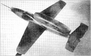
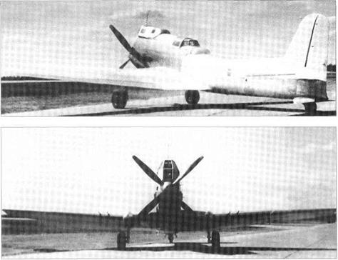
Photographs on the opposite page: Top right: Zh-01, without engine. Three views of I-270, Zh-02.

MiG I-270, Zh

Span

7.75m

25 ft 5 in

Length

8.915m

29 ft 3 in

Wingarea

12.0m2

129ft2

Weights

Empty (Zh-02)

1,893kg

4,1731b

Acid/fuel/peroxide

1,620/440/60 kg

total 4,674 Ib

Loaded

4,120kg

9,083 Ib

Performance

Maximum speed

at sea level about

936km/h

582 mph

at high altitude

l,000km/h

621 mph

Time to climb to 10,000m

2.37 min

(32,800ft)

Service ceiling

17,000m

55,775ft

Range

not measured

Take-off run

895m

2,936 ft

Landing speed (tanks dry)

137km/h

85 mph

Landingrun

493m

1,617ft

Dimensions

MiG I-270, Zh

MiG I-270, ZhMiG I-270, Zh

Moskalyov SAM-4 Sigma

Moskalyov SAM-4 Sigma

Purpose: To create a fighter with unprecedented speed.

Design Bureau: Aleksandr Sergeyevich Moskalyov, initially in Leningrad and later at the VGU and Aircraft Factory No 18, Voronezh.

Moskalyov was a talented young designer/ pilot who achieved success with convention­al aircraft, notably the SAM-5 light transport (SAM stood for Samolyot [aeroplane] Alek­sandr Moskalyov). He also persistently strove to create highly unconventional aeroplanes of tailless configurations. The first of the latter series was the Sigma, named for the letter of the Greek alphabet. He sketched this in 1933 whilst working at the Krasnyi Letchik (Red flyer) factory in Leningrad, and worked on rocket propulsion with V P Glushko in a seri­ous endeavour to design an aeroplane to reach l,000km/h (621 mph), and if possible to exceed Mach 1 (the first project in the world with this objective). When it was clear that a rocket engine with adequate thrust was many years distant, he recast the design with piston engines. He was working on this when he left Leningrad to be a lecturer at the VGU, the State University at Voronezh. Under the guid­ance of A V Stolyarov he tested models in the VGU’s newly built high-speed tunnel. In September 1934 he submitted his preliminary report on SAM-4 to the GlavAviaProm (direc­torate of aircraft industries), whose Director, 11 Mashkevich, berated Moskalyov for sub­
mitting such ‘unimaginable exotics’.

By 1933 Moskalyov had decided a suitable configuration for a fast aircraft was an all­wing layout with a ‘Gothic delta’ plan shape, with trailing-edge elevens and Scheibe sur­faces (fins and rudders on the wingtips). The drawing shows two main wheels in the front view, but this may be an error as Moskalyov favoured a single centreline gear and, as shown, skids on the wingtip fins. The drawing shows a single propeller, but in fact Moskaly-
ov intended to use two Hispano-Suiza 12 Ybrs engines, each of 860hp (these were later made in the USSR under licence as the M-100), driving separate contra-rotating pro­pellers. The stillborn rocket version would have had a prone pilot, but the piston-en­gined SAM-4 featured a conventional en­closed cockpit; the designer did not explain why this was offset to port.

This proposal was altogether too ‘far out’ for Mashkevich. No data survives.

Purpose: To test an aeroplane with landing gears on the centreline.

Design Bureau: S A Moskalyov at VGU and GAZNolS.

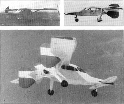
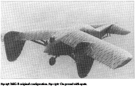
Unaware of the fact that Bartini had already flown the Stal’-6 (see page 16), Moskalyov de­cided in 1933 that it would be prudent to build a simple low-powered aeroplane to investi­gate the landing gear he proposed to use for his fighter, with a single mainwheel and skids under the wingtips and tail. It was flown in early 1934, but later in that year it was modi­fied into the SAM-65/s.

The SAM-6 had a conventional tail, though its moment arm was very short and the air­craft was dominated by its relatively huge wing. The structure was wood, with fabric – covered control surfaces. The engine was a three-cylinder M-23 rated at 65hp. Behind the small fuel tank was the open cockpit. The Scheibe fins were not fitted with rudders, and were described by the designer as ‘plates’. Initial testing was done in early 1934 on centreline tandem skis. Later the front ski was replaced by a wheel on a sprung leg in­side a trouser fairing. After rebuilding as the SAM-66/s testing continued in 1935. This had tandem cockpits with hinged hoods, and in its final form a conventional landing gear was fitted with two trousered mainwheels.

According to Shavrov ‘experiments showed that the centreline gear was quite practical’. Moskalyov intended to use such landing gear on the SAM-7, but ultimately decided not to (see original drawing of that aircraft). The fol­lowing specification refers to the SAM-6t»/s.

Moskalyov SAM-4 SigmaПодпись: SAM-66/s Top right: SAM-6.

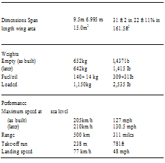
Dimensions Span Length Wing area

8.0m

4.5m

12.0m2

26 ft 3 in 14 ft 9 in 129ft2

Weights

Empty

380kg

838 Ib

Fuel

50kg

HOlb

Loaded

500kg

l,102lb

Performance

Speed at sea level

130km/h

81 mph

Service ceiling

3,000 m

9,842ft

Range

200km

124 miles

Landing speed

55km/h

34 mph

Подпись:Purpose: To build a superior two-seat fighter.

Design Bureau: A S Moskalyov, at GAZ No 18, Voronezh.

In 1934 Moskalyov was engaged in engineer­ing later versions of TB-3 heavy bomber for production. This enabled him to use one of this bomber’s engines and propellers to power a fighter (though it was hardly ideal for the purpose). Despite the fact that it was far more complex than any of his previous air­craft, and also had advanced all-metal con­struction, the SAM-7 was completed in October 1935. Pilots considered it potentially dangerous, and factory testing was confined to taxying at progressively higher speeds, ulti­mately making short hops in a straight line.

The SAM-7’s configuration was described by Shavrov as ‘one of the world’s most un­
orthodox’, but in fact the wing was of fairly normal design, with straight equal taper and an aspect ratio of 4.6. Aerofoil profile was R – II, and the thickness/chord ratio 12 per cent, without twist. Apart from this the Sigma (the designer’s second use of this name) was in­deed unconventional. There was no tail. On the wingtips were Moskalyov’s favoured Scheibe fins, fitted with fabric-covered horn – balanced rudders. On the wing trailing edge were outboard ailerons and inboard eleva­tors which, when depressed to a slight angle, were intended also to serve as slotted flaps (though it is difficult to see how they could do so without putting the aircraft into a dive). The main landing gears had single struts, raked forward, with a track of 2.8m (9ft 2in), and were pivoted to the front spar to retract inwards. The surviving drawing shows a tail – wheel, but Shavrov says there was a non-cas-
toring tailskid. The structure was almost wholly Dl duralumin, the maximum wing skin thickness being 2.5mm. The nose inlet served the carburettors. The 830hp M-34 en­gine drove a four-blade wooden propeller, and was cooled by a surface evaporative (steam) system similar to that of the Stal’-6. For use at low speeds a normal honeycomb radiator could be cranked down behind the cockpit. The intended armament was two ShKAS fixed above the engine, fired by the pilot, and a second pair mounted on a pivot and aimed by the rear gunner.

One cannot help being astonished that Moskalyov was able to obtain funds to build this aircraft, because there is no mention of any official approval of the design (which would almost certainly have been refused). One feels sympathy with the test pilots, who were probably right to be hesitant.

Подпись: Dimensions Span (Shavrov) 9.46 m 31 ft 14 in (OKB drawing) 9.6 m to centrelines of fins Length 7.0 m 22 ft 11!* in Wing area 20.0 m2 215ft2 Weights Empty 940 kg 2,072 Ib Loaded 1,480kg 3,263 Ib Performance Max speed (estimated) at sea level 435 knVh 270 mph at altitude 500km/h 311 mph Service ceiling (estimated) 9,200 m 30,184ft Range (estimated) 800 km 497 miles The only measured figure was the landing speed of 1 38 km/h 86 mph
Moskalyov SAM-4 Sigma

Original OKB drawing of SAM-7.

Moskalyov SAM-4 SigmaPurpose: To test at modest speeds an aircraft with a ‘Gothic delta’ wing of very low aspect ratio.

Design Bureau: A S Moskalyov, from 1936 head of his own OKB-31 at Voronezh.

Always eager to build his incredible SAM-4 dart-like fighter, Moskalyov was rebuffed in these efforts until in 1936 US magazines fea­tured futuristic fighters with low-aspect-ratio wings, shaft drives and prone pilots. This spurred GUAP to invite Moskalyov at least to try out his radical ideas with a simple aircraft with an engine of modest power. Following tunnel tests by V P Gorskiy at CAHI (TsAGI), the SAM-9 was built in 70 days, and flown on skis in early 1937 by N S Rybko at Voronezh. Following six flights by Rybko and A N Gusarov, it was taken to Moscow and tested in short hops by Rybko and A P Chernavskii, finally making eight full flights in the hands of Rybko. The aircraft was tricky, demanding an angle of attack of 22° at take-off and landing, and being unable to climb higher than 1,500m (4,921ft). Despite this the NKAP (state com­missariat for aviation industry) suggested that Moskalyov should produce a fighter with a 0.975 aspect ratio wing, and this led to the RM – l. SAM-29.

The SAM-9 Strela (Arrow) was made of wood, with a brilliant surface finish, the cable-operated rudder and elevons having fabric covering. The thick aerofoil was of RAF.38 profile, with local modifications. The cockpit was placed between the two main spars, with a hinged canopy. The engine was a Renault MV-4 aircooled inverted 4-cylinder rated at 140hp. The neat main landing gears had pivoted rubber-sprung cantilever legs for skis or wheels, and the tailskid did not castor. The rudder and broad-chord elevons had trim tabs.

Dimensions Span Length Wing area

3.55m

6.15m

13.0m2

Ilft53/4in 20 ft 2 in 140 ft2

Weights

Empty

470kg

l,0361b

Fuel and oil

60+10 kg

132+22 Ib

Loaded

630kg

l,3891b

Performance

Maximum speed actually

reached, at sea level

310km/h

195 mph

Altitude reached

1,500m

4,921 ft

Take-off run about

200m

656ft

Landing speed/

102km/h

63 mph

run

100m

328ft

Without the support of CAHI (TsAGI) and the (mistaken) belief that such aircraft were planned in the USA, this project would prob­ably have got nowhere. As it was, the SAM-9 merely showed that such aircraft could fly,

Moskalyov SAM-4 Sigma

but with difficulty. In a recent display ofmod – els of Moskalyov aircraft the SAM-9 was de­picted entirely doped red except for the propeller blades, and with a placard giving speed and altitude as 340km/h and 3,400m.

Moskalyov SAM-4 Sigma

Purpose: To design a small fighter with ‘push/pull’ propulsion.

Design Bureau: A S Moskalyov, OKB -31 at Voronezh.

This small fighter was unconventional in lay­out, but used an ordinary wing, and had noth­ing to do with the designer’s previous fighter concepts. According to Shavrov ‘Fokker de­signed an almost exact copy of the SAM-13, known as the D.23…’ In fact it was the other way about, because Moskalyov began this de­sign in 1938, immediately after the D.23 had been exhibited at the Paris Salon. The single prototype was first flown by N D Fikson in late 1940, 18 months after the Dutch fighter, and proved difficult to handle, to need inordinate­ly long runs to take off and land, and to have a sluggish climb and poor ceiling. Its designer worked round the clock to improve it, and by
spring 1941 it was undergoing LII testing in the hands of Mark L Gallai. Apart from the fact the nose gear never did retract fully, it was by this time promising, and it was entered for the summer high-speed race, but the German in­vasion on 22nd June stopped everything. The No 31 OKB was evacuated, but this aircraft had to be left behind so it was destroyed. The OKB documents have not been found.

The SAM-13 was powered by two 220hp Renault MV-6 inverted six-cylinder aircooled engines driving 2.2m (7ft 21/2in) two-blade variable-pitch propellers. Between them was the pilot, and Moskalyov fitted the rear pro­peller with a rapid-acting brake to make it safer for the pilot to bail out. The small two – spar wing was sharply tapered, and was fitted with split flaps inboard of the booms carrying the single-fin tail. Apart from welded steel – tube engine mounts, the structure was wood­
en, with polished doped ply skin. The main landing gears retracted inwards and the nose unit aft. One drawing shows the nose unit (which had a rubber shimmy damper) to have had a levered-suspension arm for the axle. The intended armament, never fitted, comprised four 7.62mm ShKAS, two above the front engine and two at the extremities of the wing centre section.

Moskalyov SAM-4 Sigma

Moskalyov knew that the MV-6 was avail­able for licence-production in the USSR, and thought this aircraft might make good use of some. Even had the programme continued without interruption it is hard to envisage the SAM-13 being adopted by the WS.

Dimensions (note: Shavrov’s dimensions

are incorrect)

Span

7.3m

23ftllAin

Length

7.85m

25 ft 9 in

Wing area

9.0m’

96.9ft2

Weights

Empty

754kg

l,6621b

Loaded

1,183kg

2,608 Ib

Performance

Max speed (design figures)

at sea level

463km/h

288 mph

at 4,000m (13,123 ft)

680km/h

423 mph

Service ceiling (estimate)

10,000m

32,808 ft

Range (estimate)

850 miles

528 miles

Landing speed

125km/h

78 mph

Purpose: To renew attempt to build a rocket-engined interceptor.

Design bureau: A S Moskalyov, No 31.

During the Great Patriotic War practical rock­et engines for manned aircraft became avail­able. Moskalyov never forgot that he had been invited by the NKAP to build a fighter with the so-called Gothic delta wing of 0.95 aspect ratio. In 1944, despite much other work, he collaborated with L S Dushkin in planning what was to be the ultimate Strela
fighter. This time most of the technology ex­isted, and S P Korolyov lent his support, but once the War was over such a project was judged to be futuristic and unnecessary. Moskalyov’s OKB was closed in January 1946, and he returned to lecturing, but he contin­ued to study this project for two further years.

The final SAM, also called Raketnyi Moska – lyov, would have followed the usual Strela form in having a Gothic delta wing and no horizontal tail. The wing was fitted with elevens and blended into a needle-nosed
fuselage carrying a large fin and rudder. The Dushkin RD-2M-3V engine, rated at 2,000kg (4,409 Ib) thrust at sea level and much more at high altitude, was installed at the rear and fed with propellants from tanks filling most of the airframe. Two cannon would have been installed beside the retracted nose landing gear.

This was yet another of this designer’s near misses, all of which stemmed from his abun­dance of enthusiasm.

No data survives.

Moskalyov SAM-4 Sigma

Two sketches, one called SAM-29, the other RM-1.

Moskalyov SAM-4 Sigma


Moskalyov SAM-4 Sigma

Sukhoi Su-7R

Подпись: Dimensions (final standard) sPan 13.5m 44 ft 3Л in Len§'h 10.03m 32 ft 103/i in Wing area 26.0m2 280 ft2 Подпись:Sukhoi Su-7RПодпись: Aircraft A (Su-6). In 1942 he was authorized to develop the A into a single-seat fighter This flew in late 1943 and underwent various modifications, in its final form being tested by G Komarov between 31st January and 20th December 1945. By this time it was no longer of interest. The Su-7R was based upon the airframe of the Su-6(A), but with a new all-metal semi- monocoque fuselage. The two-seat cockpit

Purpose: To create a mixed-power (piston engine plus rocket) fighter.

Design Bureau: OKB of Pavel Osipovich Sukhoi, Moscow. Note: this aircraft was not related to the later Su-7 jet fighter.

Having in 1941 seen the Su-2 attack bomber accepted into production, Sukhoi subse­quently never dislodged the IL-2/IL-10, de­spite the excellence of different versions of
was replaced by a single-seat cockpit with a unged canopy with a fairing behind it. An ad­ditional fuel tank replaced the internal weapons bay, and the large-calibre wing guns were removed, the armament being three synchronized ShVAK 20mm cannon each with 370 rounds. At first the ASh-71 type engine was retained, but this was soon re­placed by a smaller and less-powerful ASh – 82FN, rated at l,850hp on 10o-octane fuel driving an AV-9L four-blade propeller. In 1944 aTK-3 turb o sup ercharger was added on each side, and an RD-lKhZ rocket engine was in­stalled in a new extended tailcone. As de­scribed previously, this Dushkin/Glushko engine had a single thrust chamber burning the same petrol (gasoline) as the piston en­gine, which ignited hypergolically (instant re­action) when mixed with RFNA (red fuming nitric acid). The acid was housed in an addi­tional tank behind the cockpit, with access through a dorsal hatch. This tank gave a con­tinuous burn time of about four minutes. When rocket power was selected, the pro­pellants were fed at a rate of 1.6kg (3.5 Ib) per second, giving a thrust of300kg (661 Ib) at sea level and about 345kg (761 Ib) at high altitude.

By 1945 this aircraft was no longer compet­itive, and the rocket engine never went into production. In any case, during a practice for the first post-war air display in late 1945 the rocket engine exploded, casing a fatal crash.

3,250kg 7,1651b

480/50/1 80 1,058/110/397Ib

4j36°kg 9,612 Ib

Sukhoi Su-7R

Performance Maximum speed

at sea level (no rocket) 480 km/h

at 7.5 km (24,600 ft) with rocket 680 km/h at 12 km (39,370 ft) with rocket 705 km/h Service ceiling 12,750m

Range (with full rocket bum) 800 km Take-off 300 m

Landing speed/ 125 km/h

350m


298 mph 423 mph 438 mph 41,831 ft 497 miles 984ft 78 mph 1,148ft


Sukhoi Su-7R

Sukhoi Su-7R

Tsybin RSR, R-020

Tsybin RSR, R-020

Purpose: To improve the RSR further.

Design Bureau: OKB-256, Podberez’ye, later repeatedly transferred (see below).

Upon receipt of data from the NM-1, the RSR had to be largely redesigned. Construction was only marginally held up, and in early 1959 drawings for the first five pre-series R-020 air­craft were issued to Factory No 99 at Ulan-Ude. However, Tsybin’s impressive aircraft had their commercial rivals and political enemies, some ofwhom just thought them too ‘far out’, and in any case vast sums were being transferred to missiles and space. On 1st October 1959 President Khrushchyev closed OKB-256, and the Ministry transferred the RSR programme to OKB-23 (General Constructor VM Mya – sishchev) at the vast Khrunichev works. The Poberez’ye facilities were taken over by A Ya Bereznyak (see BI story). The Khrunichev management carried out a feasibility study for construction of the R-020, but in October 1960 Myasishchev was appointed Director of CAHI (TsAGI). OKB-23 was closed, and the entire Khrunichev facility was assigned to giant space launchers. The RSR programme was there­upon again moved, this time to OKB-52. At first this organization’s General Constructor V N Chelomey supported Tsybin’s work, but in­creasingly it interfered with OKB-52’s main programmes. In April 1961, despite the difficul­ties, the five R-020 pre-series aircraft were es­sentially complete, waiting only for engines. In that month came an order to terminate the pro­gramme and scrap the five aircraft. The work­force bravely refused, pointing out how much had been accomplished and how near the air­craft were to being flown. The management quietly put them into storage (according to

V Pazhitnyi, the Tsybin team were told this was ‘for eventual further use’). Four years later, when the team had dispersed, the aircraft were removed to a scrapyard, though some parts were taken to the exhibition hall at the MoscowAviation Institute.

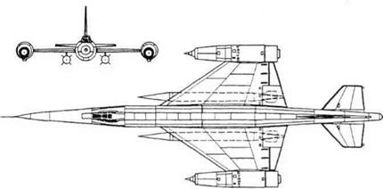
The airframe of the 1960 RSR differed in sev­eral ways from the 1957 version. To avoid sur­face-to-air missiles it was restressed to enable the aircraft to make a barrel roll to 42km (137,800ft). The wings were redesigned with eight instead of five major forged and ma­chined ribs between the root and the engine. The leading edge was fitted with flaps, with maximum droop of 10°. The trailing edge was tapered more sharply, and area was main­tained by adding a short section (virtually a strake) outboard of the engine. These exten­sions had a sharp-edged trapezoidal profile. According to Tsybin These extensions, added on the recommendation of CAHI, did not pro­duce the desired effect and were omitted’, but they are shown in drawings. In fact, CAHI real­ly wanted a total rethink of the wing, as related in the final Tsybin entry. The tailplane was re­designed with only 65 per cent as much area, with sharp taper and a span of only 3.8m (12ft 5%in). Its power unit was relocated ahead of the pivot, requiring No 6 (trim) tank to be moved forward and shortened. The fin was likewise greatly reduced in height and given sharper taper, and pivoted two frames further aft. The ventral strake underfin was replaced by an external ventral trimming fuel pipe. The main landing gear was redesigned as a four – wheel bogie with 750 x 250mm tyres, and the outrigger gears were replaced by hydraulically extended skids in case a nacelle should touch the ground. The pilot was given a better view,
with a deeper canopy and a sharp V (instead of flat) windscreen. The camera bay was re­designed with a flat bottom with sliding doors. The nose was given an angle-of-attack sensor, and a pitot probe was added ahead of the fin. The drop tanks were increased in diameter to 700mm (2ft 31/2in) but reduced in length to 5.8m (19ft) instead of 11.4m (37ft 4Min). Not least, the D-21 engines never became available, and had to be replaced by plain afterburning turbojets. The choice fell on the mass-produced Tuman – skii R-l IF, each rated at 3,940kg (8,686Ib) dry and 5,750kg (12,676 Ib) with afterburner. These were installed in longer and slimmer nacelles, with inlet sliding centrebodies pointing straight ahead instead of angled downwards.

There is no reason to doubt that the pre-se­ries RSR, designated R-020, would have per­formed as advertised. It suffered from a Kremlin captivated by ICBMs and space, which took so much money that important aircraft programmes were abandoned. The United Kingdom similarly abandoned the Avro 730, a reconnaissance bomber using identical tech­nology, but in this case it was for the insane rea­son that missiles would somehow actually replace aircraft. Only the USA had the vision and resources to create an aircraft in this class, and by setting their sights even higher the Lockheed SR-71 proved valuable for 45 years.

Dimensions

Span (with small tip extensions) 10.66 m

34 к 1 13/ in

Length (excl nose probe)

28.0 m

91 ft 10% in

Wing area

64 m2

689 ft2

Weights

Empty

9,100kg

20,062 Ib

Fuel

10,700kg

23,589 Ib

Loaded

19,870kg

43,805 Ib

Performance

Cruising speed at reduced

altitude of 12 km (39,370 ft) 2,600 km/h

1,616 mph (Mach 2.44)

Service ceiling

22,500 m

73,819ft

Range

4,000 km

2,486 miles take-off

Take-off run

1,200m

3,937ft

Landing speed/run

2 1 0 km/h

130.5 mph

(with braking parachute)

800 m

2,625 ft

R-020 centre fuselage at MAI.

Tsybin RSR, R-020

Bartini Stalf-7

Purpose: Originally, fast passenger transport; later, long-range experimental aircraft.

Design: SNII GVF; construction at GAZ (Factory) No 81, Moscow Tushino.

In the winter 1933-34 the GUGVF (chief ad­ministration of the civil air fleet) issued a re­quirement for a fast transport aircraft to carry 10 to 12 passengers. Curiously, the two proto­types built to meet this demand were both the work of immigrant designers, the Frenchman Laville (with ZIG-1) and the Italian Bartini. The latter had already produced drawings for a transport to cruise at 400km/h (248mph), which was well in advance of what the GVF had in mind. Always captivated by speed, Stalin decreed that a bomber version should be designed in parallel. Still in charge of de­sign at the SNII GVF, Bartini refined his study into the Stal’-7, the name reflecting its steel construction.

Strongly influenced by the Stalin decree, Bartini created a transport notable for its cramped and inconvenient fuselage, highly
unsuitable for passengers but excellent for bombs, and for long-range flight. The original structure was to be typical Bartini welded steel-tube trusses with fabric covering, but the stress calculations were impossibly diffi­cult, with 200 primary rigid welded intersec­tions between tubes of different diameters. In late 1934 the fuselage was redesigned as a light-alloy stressed-skin structure, with sim­pler connections to the unchanged wing.

Only one aircraft was built, in the work­shops ofZOK, the factory for GVF experimen­tal construction. The first flight was made on an unrecorded date in autumn 1936, the pilot being N P Shebanov. Performance was out­standing, and Shebanov proposed attempting a round-the-world flight. In 1937 the StaP-7 was fitted with 27 fuel tanks with a total ca­pacity of 7,400 litres (1,628 Imperial gallons, 1,955 US gallons). A maximum-range flight was then attempted, but – possibly because of structural failure of a landing gear – the air­craft crashed on take-off. Bartini was arrest­ed, and was in detention (but still designing, initially at OKB-4, Omsk) for 17 years.

The aircraft was repaired, and on 28th Au­gust 1939, at a slightly reduced weight, suc­cessfully made a closed-circuit flight of 5,068km (3,149 miles) in 12hrs Slmin (aver­age speed 404.936km/h, 251.62mph), to set an FAI Class record. The route was Moscow Tushino-Maloe Brusinskoe (Sverdlovsk re – gion)-Sevastopol-Tushino, and the crew comprised Shebanov, copilot VAMatveyev and radio/navigator N A Baikuzov. In Bartini’s absence, the project was seized by his op­portunist co-worker V G Yermolayev, who re­designed it into the outstanding DB-240 and Yer-2 long-range bomber.

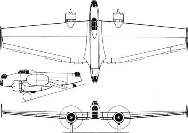
The wing was typical Bartini, with pro­nounced straight taper and construction from complex spars built up from multiple steel tubes, almost wholly with fabric covering. Each wing comprised a very large centre sec­tion, with depth almost as great as that of the fuselage, terminating just beyond the engine nacelles 2.8m (9ft 2/4in) from the centreline, with sharp anhedral, and thinner outer panels with dihedral. The trailing edges carried split flaps and Frise ailerons, the left aileron having

Bartini Stalf-7Bartini Stalf-7Bartini Stalf-7a trim tab. One account says that the inverted – gull shape ‘improved stability and provided a cushion effect which reduced take-off and landing distance’, but its only real effect was to raise the wing on the centreline from the low to the mid position.

This was just what the fuselage did not need, because the massive deep spars formed almost impassable obstructions and eliminated any possibility of using the aircraft as a passenger airliner. The fuselage was a light-alloy structure, with an extremely
cramped cross-section with sides sloping in towards the top (almost a round-cornered tri­angle). Entry was via a very small door on the left of the rear fuselage. The cockpit in the nose seated pilots side by side, and had a glazed canopy with sliding side windows and the then-fashionable forward-raked wind­screen. Immediately behind the cockpit there was a station for the navigator/radio operator. The tail surfaces, made of dural/fabric, were of low aspect ratio, the elevators having tabs.

The engines were the 760hp M-100, these being the initial Soviet licence-built version derived by V Ya Klimov from the Hispano – Suiza 12Ybrs. They were installed in neat cowlings at the outer ends of the centre sec­tion, angled slightly outwards and driving pro­pellers with three metal blades which could have pitch adjusted on the ground. One ac­count states that wing-surface radiators were used, but it is obvious from photographs that ordinary frontal radiators were fitted, as in the Tupolev SB bomber. Plain exhaust stubs were fitted, though this may have scorched the wing fabric and one drawing shows ex­haust pipes discharging above the wing. In the course of 1938-39 the original engines were replaced by the derived M-103, rated at 860hp, which improved performance with heavy fuel loads. A hydraulic system was pro­vided to operate the flaps and the fully re­tractable main landing gears, each unit of which had a strong pair of main legs which hinged at mid-length, the unit then swinging back on twin forward radius arms (like a DC – 3 back-to-front). The castoring tailwheel was fixed. In the nose were twin landing lights.

The Stal’-7 was simply a sound aeroplane able to fly at what was in its day a very long way at high speed. As a transport it was in­convenient to the point of being useless, though it was supposed to be able to seat 12 passengers, and it was flawed by its basic lay­out and structure. The Soviet Union was right to take a licence for the Douglas DC-3. On the other hand, Yermolayev transformed the Stal’-7 into an outstanding long-range bomber.

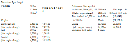
Dimensions Span Length Wing area

23.0 m

16.0m

72.0 m2

75ft 5n in 52 ft 6 in 775ft2

Weights

Empty

4,800 kg

1 0,580 Ib

Loaded (originally)

7,200 kg

1 5,873 Ib

Maximum loaded ( 1 939)

1 1 ,000 kg

24,250 Ib

Performance

Max speed at 3,000m (9,842 ft) 450km/h 280 mph

Cruising speed 360/380 km/h 224/236 mph

Service ceiling

(disbelieved by Gunston) 1 1 ,000 m 36,090ft

(on one engine, light weight) 4,500 m 14,764ft

Left: Two views of Stal’-7.

BOK-7, K-17

Purpose: To continue stratospheric-flight research with an aircraft superior to BOK-1. Design Bureau: Bureau of Special Design, Smolensk. Chief designer Chizhevskii.

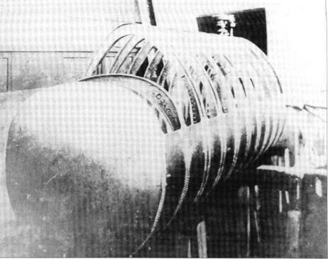
Design of this aircraft began in 1936. The Tupolev RD was again used as the starting point, but with features intended to enable greater heights to be reached. The test pilots were Petrov and Stefanovskii. According to Shavrov the BOK-7 was first flown in 1938, and ‘showed the same characteristics as the BOK-1’. Several two-man crews, including such important long-distance pilots as Gro­mov, Yumashev, Danilin, Spirin, Baidukov, Belyakov and others, spent periods of several days sealed in the GK checking all aspects of human life in preparation for proposed high- altitude long-distance flights in the BOK-15. According to some historians the ultimate ob­jective was a high-altitude circumnavigation, and that the by-function designation of this aircraft was K-17, from Krugosvetnyi (round the world). Photographs originally thought to be of the BOK-7 are now known to show the BOK-11.

The BOK-7 had the full-span wing of the RD, and aft-retracting landing gears, but com­pared with the RD the legs were redesigned for much lighter gross weight, and fitted with single wheels. Attention was concentrated on the fuselage, which unlike the BOK-1 had the GK (pressure cabin) integral with the air­frame, the centre fuselage being a slim cylin­der sealed by gaskets and adhesives, and with grommets fitting round the control wires and other services passing through apertures in the wall. The normal oxygen supply to the pilot and pilot/observer ‘compensated for the insignificant amount of air escaping’. The sealed drum was fitted with two hemispheri­cal domes, the front with eight and the rear with six transparent portholes so that the oc­cupants could see out, with a better view than from the BOK-1. The GK was kept at pressure by a tapping from a centrifugal PTsN (super­charger) blower driven by step-up gears from the engine. The engine was an 890hp M-34FRN fitted with two TK (turbosuper­chargers). It is probable that these delivered compressed air to the PTsN which then fed the engine, the cabin supply being taken off a small bleed pipe. Shavrov states that ‘all sys­tems worked well’, and that the experiments were ‘very interesting’.

According to Shavrov this aircraft had ‘the first GK of the combined type’ with both a sealed compartment kept under pressure and an oxygen supply. Some accounts state that AI Filin at the NIl-WS worked out details of the proposed circumnavigation, in 100- hour stages, but that the project was aban­doned after he was arrested in 1939 and executed in Stalin’s Terror of 1940. This air­craft led to the BOK-8, BOK-11 and BOK-15, but it appears that no illustrations of it have been discovered.

Dimensions

Span

34.0m

111 ft W in

Length

12.9m

42 ft 4 in

Wing area

87m2

936.5 ft2

Weights

Empty

3,900kg

8,598 Ib

No other data.

Kharkov KhAI Aviaviiito 3, Sergei Kirov

Purpose: To create a light transport with minimum operating cost.

Design Bureau: Kharkov Aviation Institute, Aviavnito brigade led by Aleksandr Alekseyevich Lazarev.

In the 1930s several Soviet designers pro­duced aircraft intended to demonstrate how much could be transported on the l00hp of an M-l 1 engine. These aircraft were as a class called Planerlyet (motor glider). This exam­ple had an unconventional configuration. It first flew on 14th September 1936, dual-con­trolled by V A Borodin and E I Schwartz. Eventually a control linkage was found which by 27th September enabled good turns to be made. Shavrov’s account ends with The

Aviavnito-3 after modification.

Kharkov KhAI Aviaviiito 3, Sergei Kirov

overall conclusion of the tests at Nil GVF (civil aviation test institute) was extremely posi­tive’, but nothing came of this one-off.

The Aviavnito-3 (often incorrectly called KhAI-3) was essentially an all-wing aircraft. The wing comprised a rectangular centre sec­tion, with the uncowled engine mounted on steel tubes on the front, to which were bolted two outer panels tapered on the leading edge. Aerofoil was V-106, with a t/c ratio of 14 per cent over the centre section, which had a chord of 5.0m (16ft Sin), tapering to 7 per cent at the tips, which incorporated 8° washout. Structurally, the centre section was KhMA steel tube covered by Dl Dural skin, while the outer panels were all wood, with truss ribs supporting closely spaced stringers. Along each outer edge of the centre section was a row of four seats, each front seat being for a pilot (the two pilots had to agree in advance which one should do the flying), covered by a row of sliding canopies. The flight controls comprised large unbalanced cable-operated surfaces divided into inner and outer sections to serve as ailerons and elevators. In addition, spoilers were recessed into the upper surface of each wingtip, driven by the pedals, to en­able co-ordinated turns to be made. A 2m2 (21.5ft2) fin and rudder were added, but it was hoped eventually to do without this. The sim­ple rubber-sprung main landing gears had 800 x 150mm tyres with brakes, and the large tailwheel could castor ±25°. Between the
rows of seats were four Dl tanks giving an 8-hour endurance. During development two additional seats were inserted on each side, pushing the pilots into noses projecting ahead of the wing. To balance these the vertical tail was significantly enlarged.

It is clear that this machine did everything expected of it, and that it was eventually de­veloped to fly safely and controllably. How­ever, even though they were much faster than anything else over vast areas devoid of sur­face transport, nothing came of the rash of Planerlyet designs.

Dimensions (final form)

Span

Length

Wing area

22.4m 6.8m 78.6 m!

73 ft 6 in 22 ft 334 in 846 ff

Weights

Empty

1,440kg

3,1751b

Fuel/oil

200kg

440 Ib

Loaded

2,200kg

4,850 Ib

Performance

Maximum speed

135km/h

84 mph

Cruising speed

115km/h

71.5 mph

Time to climb to 1 ,000 m

25min

(3,281 ft)

Service ceiling approx

2,000m

6,561 ft

Range

850km

528 miles

Take-off run

210m

689ft

Landing speed

60km/h

37 mph

Kharkov KhAI Aviaviiito 3, Sergei Kirov