ENGAGING THE ENEMY
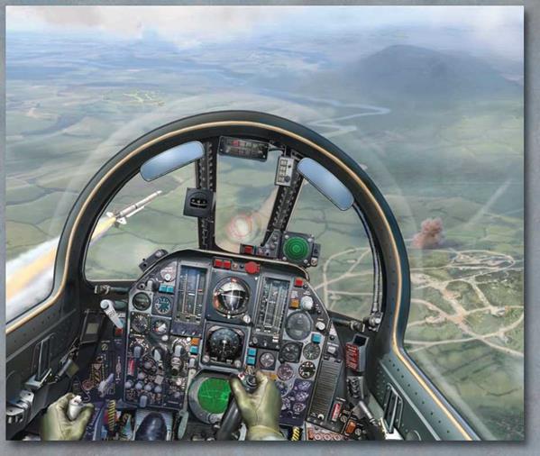
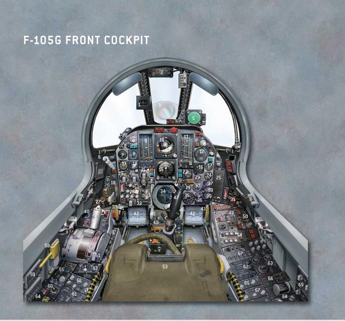
As the target was approached the back-seat “Bear” monitored his ER-142 (AN/APR-35) panoramic attack indicator’s three-band displays for signal activity, using his panoramic scope and attack indicator and his AN/APR-26/-36 azimuth indicator and threat lights. His view from the cockpit was extremely limited, so the pilot’s vision ahead was crucial. The Shrike’s nose-mounted seeker also provided the pilot with an effective radar-receiving device. Both men would listen for the high – pitched, rattlesnake-like sound – the “song” of an active “Fan Song” – from 100 miles out. Closer in, if the red azimuth sector SAM launch light came on, the pilot immediately initiated evasive maneuvers.
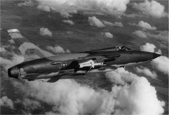
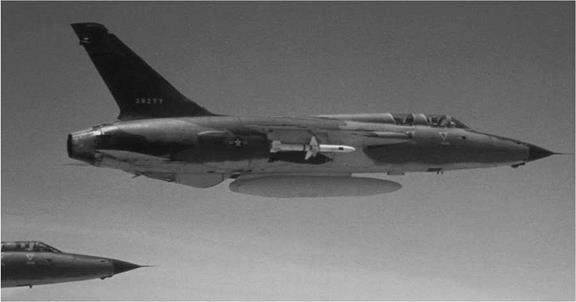
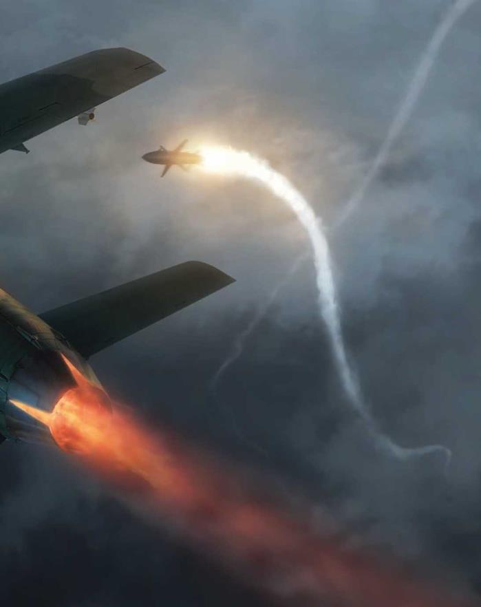
AGM-78s were launched as soon as there was a valid hostile radar return in order to use the missile’s maximum range, as well as to lighten the aircraft. The pilot climbed in afterburner while the missile warmed up, the round then being “lofted” from a distance of between 25 and 45 miles. A green “missile acquisition” light showed that the weapon had locked onto a radar, and it was launched using the red firing button on the control column. The AGM-78’s motor was ignited via a lanyard coupling, and the missile made a 5g climb before heading for the target. The crew timed its flight against the time a “Fan Song” took to go off the air, thus suggesting a successful hit.
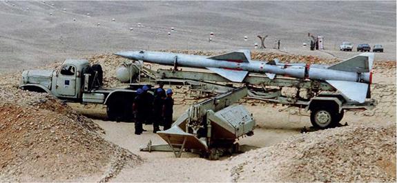
Eleven aircraft had fallen to SA-2s by the end of 1965. A Russian technician reported that, “The most impressive moment was when the aeroplanes were downed.
All of a sudden through this dark shroud an object you couldn’t even see before came down in a blaze of shattered pieces”.
Normally, battery commanders adhered to the Soviet rapid three-missile salvo method that was specifically created to tackle maneuvering targets. However, most of 55
![]()
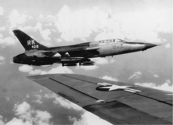
 the early kills were against targets flying straight and level at between 18,000ft and 35,000ft. Two of the SA-2 victims in 1965 were Iron HandF-105s flying at relatively low altitudes while searching for SAM batteries. Lt Col George McCleary, CO of the 357th TFS, was killed when his jet (62-4342) was hit by a missile that unexpectedly emerged from the cloud-base near Nam Dinh on November 5. Eleven days later, Capt Donald Green’s Iron Hand flight was on the look out for SAM sites near Haiphong when a quick thinking battery commander detonated an SA-2 close to his Thunderchief (62-4332). Green, from the 469th TFS, managed to nurse his crippled jet out to sea, but he perished when the fighter crashed before he could eject.
These losses prompted new guidance to Korat F-105 crews:
Never fly below 4,500ft AGL, except when evading SA-2s. Turn into the missile and descend. “Fan Songs” take up to 40—45 seconds to re-acquire an aircraft after the lock is broken, giving the F-105 time to escape. Never fly over an undercast (cloud-base) in a known SAM threat area.
Seeing the cloud of orange-brown smoke and dust kicked out by a SAM on launch was often a pilot’s best warning, but a Mach 3 SA-2 emerging from cloud after shedding its booster had a less visible smoke trail, allowing only seconds for evasion.
The extremely hazardous anti-SAM strategy known as Iron Hand, which was officially initiated on August 16, 1965 with F-105s, demanded the employment of new tactics. The initial response, however, was conventional. Following the F-4C shoot-down on July 24, 1965, the US government sanctioned retaliation with the commencement of Operation Spring High three days later. Some 54 F-105s from the 18 th, 23rd and 355th TFWs, supported by a further 58 aircraft, struck SAM Sites 6 and 7, and their barracks areas, using bombs, rockets and napalm, but with disastrous
results. Capt “Chuck” Horner was flying an 18th TFW F-105D when he saw “Bob Purcell’s F-105 (62-4252 Viet Nam ANG) rise up out of a cloud of dust with its entire underside on fire, roll over and go straight in. We were doing 650 knots, carrying cans of napalm that were limited to 375 knots! I looked out to the left and saw antiaircraft artillery lined up in rows with their barrels depressed, fire belching forth”.
Capt Purcell’s was one of six F-105Ds lost on that mission. Four fell to the 120 anti-aircraft guns in the area and the remaining pair crashed after Capt William Barthelmas’ damaged “Thud” (61-0177) became uncontrollable near his Thai base (Ubon) and collided with an escorting F-105D (62-4298) flown by Maj Jack Farr.
Both men were killed. More bad news followed, as reconnaissance photographs showed that Site 7 — manned by the 236th Missile Regiment — had been evacuated, while the “missiles” at Site 6 were fakes. Both “batteries” had been set up as flak traps in what was to become a familiar North Vietnamese tactic.
As previously mentioned, the USAF’s first official Iron Hand strike was flown on August 16, 1965, although Maj William Hosmer had led a dozen 12th TFS F-105s against SAM Site 8 three days previously. There were no losses on this occasion, but again the site was empty. This attack preceded a short period when Iron HandF-105s were placed on ground alert to respond quickly to SA-2 threats. An attack on September 16, led by Lt Col Robinson Risner, on a site near Thanh Hoa used two Iron Hand flights, with the lead F-105s loaded with napalm and the wingmen carrying 750lb bombs. Risner usually dropped napalm on the “Fan Song” vans while his wingman climbed in afterburner and then dive-bombed the missile batteries. On that raid two 67 th TFS F-105Ds, including Risner’s 61-0217, were shot down.
Iron Hand flights were soon attached to all strike missions in high-threat areas from Rolling Thunder28/29 (August 20) onwards as North Vietnam’s SAM network rapidly expanded. From November 1965 F-105s made low-level approaches to SAM sites with a “pop-up” climb to 4,000ft to launch 2.75in. high-velocity aerial rockets.
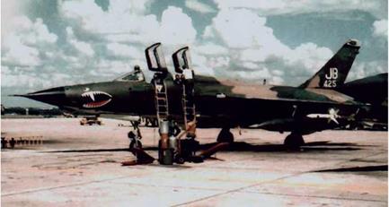
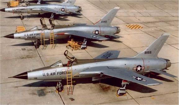
The first Wild Weasel III-1 F-105Fs arrived at Korat RTAFB in great secrecy in May 1966. As a 13th TFS flight within the 388th TFW, the Weasels accompanied all the wing’s important strike packages in hunter-killer teams (F-105Fs paired up with F-105Ds) against SA-2 sites around petrol-oil-lubricant and transportation targets.
Of the flight’s 12 assigned F-105Fs, only one (63-8286) was lost when Maj Roosevelt Hestle and Capt Charles Morgan (“Pepper 01”) were hit by 57mm AAA during an Iron Hand attack on a site near Thai Nguyen on July 6. The blazing aircraft flew into a hillside, killing both crewmen — Capt Morgan duly became the first F-105F EWO casualty of the conflict.
In January 1967, the 13th TFS flew Iron Hand alongside 354th TFS Weasels in support of Operation Bolo (an elaborate combat “sting” that saw F-4 fighters of the 8 th TFW concealed within a radiated image that simulated bomb-laden F-105s in an effort to trick VPAF MiGs into combat) and the ongoing heavy strikes on North Vietnam’s industrial facilities.
Eight months later, on August 11, 13th TFS commander Lt Col James McInerney and his EWO Capt Fred Shannon were awarded the Air Force Cross for their actions
during a mission against the Paul Doumer Bridge. Braving extremely heavy AAA and 5 7
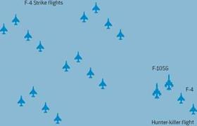
three SA-2s, they successfully eliminated three SAM sites without loss. This crew pioneered the Weasel tactic called “trolling” in which the F-105 flight flew about ten minutes ahead of the main force to search for missile sites without interference from airborne jammers. This tactic evolved into a pattern of two elements flying “figure – of-eight” orbits near a known site, with one pair of F-105s always heading towards the missile battery to threaten it with Shrikes.
The 13th TFS was a casualty when the 388 th TFW shrunk to three squadrons in October 1967 due to attrition, its assets being passed to the 44th TFS, which continued the Korat Weasel duty until October 10, 1969.
At Takhli RTAFB, F-105F Weasels had initially arrived for the 354th TFS in early 58 July 1966. Whereas Korat aircraft were assigned only to the 13th TFS, the 355th
TFW planned a Weasel flight of up to six aircraft for each of its squadrons, beginning with the 354thTFS on July 4, 1966. The latter unit’s Takhli Weasel cadre had lost all four of its original F-105F complement within a month of commencing operations. Two of these fell to SA-2s, Majs Gene Pemberton and Ben Newsom being the first 355 th Weasel loss when F-105F 63-8338 was hit at high altitude on July 23.
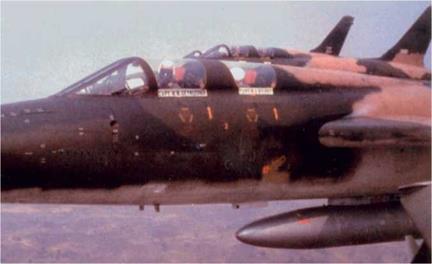 “Lincoln” Wild Weasel flight maintain close formation for the benefit of the photographer during Capt Merlyn Dethlefsen’s March 10, 1967 Medal of Honor mission. Capt Gilroy’s name appears on the aircraft’s rear canopy rail, but the pilot’s “name-plate” is incorrectly spelt CAPT M H DETHLESSEN! (Paul
Chesley/USAF) 59
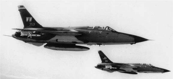
Two were shot down on August 7, as were three F-105Ds. Capts Ed Larson and Mike Gilroy fired a Shrike from F-105F 63-8358 that probably knocked out a “Fan Song”, but they were then tracked by a second site, which they also fired at. Seconds after the Shrike left their aircraft they had to evade an SA-2, but a second “Guideline” suddenly emerged from cloud in front of them and detonated. Usually, successful evasion required 6,000—8,000ft of altitude above the height at which an oncoming missile had first been sighted.
The F-105’s 20mm ammunition drum exploded, filling the cockpit with smoke. Unable to see the canopy jettison handle, Capt Gilroy initiated ejection but stopped the sequence after the canopy had been jettisoned. He could then see a large hole in the wing, and also noted the absence of the top of the tail fin and the aircraft’s nose, but the wounded “Thud” continued to head for the coast at 500 knots. A final flak burst severed a hydraulic line, forcing the crew to eject into the sea for recovery by an HU-16 amphibian. Minutes later a second 354th TFS Weasel (63-8361) was hit by 85mm AAA as it took on a SAM site near Kep airfield, forcing Capts Bob Sandvick and Thomas Pyle to eject into captivity in Hanoi. This left only one Weasel F-105F at Takhli until replacement aircraft arrived. The 355th TFW destroyed several SA-2 sites during the rest of the year.
On December 19, 1967 a 333rd TFS Weasel crew added half a MiG-17 to the two already downed by Weasel F-105s. Majs William Dalton and James Graham (flying F-105F 63-8329 The Protestor’s Protector) used 20mm gunfire to finish off the VPAF fighter after an 8th TFW F-4D crew had damaged it. Dalton reported that he “observed impacts on the left wing and fuselage under the cockpit” before the MiG broke away. This Thunderchief, upgraded to F-105G configuration, was lost on January 28, 1970 during an escort for an RF-4C Phantom II photographing a SAM site. At that time, “protective reaction” missions allowed escorting fighters to retaliate to ground fire. When Capts Richard Mallon and Robert Panek dived to strafe an aggressive AAA site their F-105G was shot down, and an HH-53 helicopter that tried
to rescue them was destroyed by a MiG-21. Both F-105G crewmen and six rescuers were killed, the former reportedly being executed after their capture by North Vietnamese militiamen.
The AGM-45 was vital to the F-105F’s SEAD mission from the outset, although crews quickly discovered that the weapon’s small warhead was effective only against the radar antennas it homed onto. Lt Col Robert Belli recalled, “When we fired at ‘Fire Can’ radars or a SAM site we found that within 24 hours the same site was ‘up’ once again in the general area. We figured all they did was change the antenna”.
Iron Hand jets usually flew about seven minutes (later down to just one to two minutes) ahead of the main strike package in the hope of “bringing up” hostile radar emitters and destroying them before they could threaten the strikers. A four-aircraft flight approached the target at 6,000—9,000ft and around 500 knots, dividing into two elements nearer the target — one monitored potential threat radars while the other suppressed known threats. Weasels tried to be unpredictable in order to outwit the SA-2 batteries, although missile crews could adapt their rigid Soviet training to keep pace with the Weasels moves. Having protected the strike, Weasel crews waited to cover the fighters’ exit, thus living up to their “first in – last out” motto.
Among the early F-105F Weasel pilots was Capt Mike Gilroy, who reported that SAM sites were “extremely difficult to acquire visually and looked just like the villages or jungle close by”. Those pilots with luck on their side might catch sight of a dust cloud as an SA-2 was launched, thus giving them a few precious seconds to take appropriate evasive action before attacking the site.
As the CO of the 469th TFS, Maj Bob Krone played an important role in the early operational integration of the Weasels within the 388th TFW:
As the Weasel aircraft had no range estimation capability, the searching was haphazard and
could not be carefully pre-planned. The SA-2 sites were invariably in heavily defended
areas protecting the “hard” targets. In many areas there was more than one site within range of the Iron Hand flight. This forced the Iron Hand crews to expose themselves to the heaviest concentration of enemy anti-aircraft fire in North Vietnam, in addition to the SAM threat. The use of free-fall bombs or unguided rockets by the strike aircraft necessitated visual acquisition of the site before destruction could be expected. The necessary maneuveres to deliver these weapons also required considerable exposure to enemy defenses.
It was the consensus of pilots of the 469th TFS that the early concept of operations should have been the protection of the strike force through detection and avoidance of SA-2 sites, rather than search and destroy. With the acquisition of the AGM-45A Shrike, there was no longer the requirement for visual acquisition of the target, and the same harassment could be effected without the high degree of risk to the attacking flight. However, the weapon’s small warhead, the inability of the early Shrike to discriminate and track one radar signal and the lack of an adequate tracking flare and spotting charge were limitations to effective Shrike employment.

![]() The last two shortcomings detailed by Maj Krone meant that pilots could not use an AGM-45A Shrike to mark a target effectively, as its flight could not be followed
The last two shortcomings detailed by Maj Krone meant that pilots could not use an AGM-45A Shrike to mark a target effectively, as its flight could not be followed
© Osprey Publishing • www. ospreypublishing. com
|
|
visually by either the launch jet or other aircraft in the immediate area. Both areas were eventually addressed with the AGM-45A-2, which boasted a tail-mounted flare and a white phosphorus target marker within the warhead of the weapon.
When attacking a “Fan Song”, the pilot had to fly directly towards the target emitter, using azimuth and elevation indicators and visual clues to identify the radar’s location. Calculating altitude, speed and estimated distance from the target, he could then work out the optimum “loft angle” for the missile by using a kneepad graph. “Lofting” the missile from a 30- to 45-degree climb significantly increased the Shrike’s range and dive impact, and kept the F-105 further from the SAM site. Even so, as F-100F EWO Capt Jack Donovan observed, the Shrike’s range, speed and guidance limitations compared with the SA-2 made the contest “like fighting a long sword with a pen-knife in an elephant stampede”! Donovan was also credited with originating the Wild Weasels long-standing motto, “YGBSM — you gotta be shitt’n me”.
The 1967 Korat Tactics Manual advised that “unless the flight leader knows exactly where the SAM/Tire Can’ is located and can plan a surprise attack, it is generally good practice to initiate an attack with a Shrike to place a tracking radar site on the defensive and buy time for the flight to penetrate the critical zone between the enemy’s maximum and minimum effective range”.
 Weasels also flew hunter-killer missions in allocated “free-fire” zones, where they could find targets of opportunity. Some of these were performed at night, often as elements divided into single-aircraft SAM hunts.
After an uncertain start (there was an outbreak of booing from 355 th TFW pilots when it was first announced that pods would replace some of their bombs), all Thunderchiefs were QRC-160-1 pod-equipped by November 1966. The disastrous
|
|
|
||||||||||||||||||||||||
|
||||||||||||||||||||||||
|
||||||||||||||||||||||||
|
||||||||||||||||||||||||
|
||||||||||||||||||||||||
|
![]()
losses (72 F-105s in the period April-September 1966 prior to adoption of the pods) over Route Pack 6 were reduced by two-thirds — North Vietnam was divided up into areas of responsibility, or “Route Packages”, by the USAF and US Navy, and their strike aircraft stuck religiously to their assigned “packs”. Col Bill Chairsell, commanding Korat’s 388th TFW, observed, “The introduction of the QRC-160-1 (AN/ALQ-71) pod to the F-105 represents one of the most effective operational innovations I have ever encountered. Seldom has a technological advance of this nature so degraded an enemy’s defensive posture”.
Although most of the 72 losses were caused by AAA, the pods restricted F-105D/F SAM shootdowns to just three between October 1966 and March 1967 — 18 aircraft of other types were downed by the missiles during the same period. One of the three “Thuds” lost was Iron Hand F-105F 63-8262 “Magnum 03”, which was trying to lure an SA-2 site into firing at it on February 18, 1967. The jet took a hit seconds after launching a Shrike from just above a 10,000ft cloud base, Capts David Duart and Jay Jensen (on their 13th mission) becoming PoWs for the next six years.
As ECM pod technology advanced, the effect on SAMs was dramatic. During August 1967 in excess of 65 per cent of the SA-2s launched lost control soon after being fired, and several crashed into Hanoi, causing substantial casualties. In mid – December 1967 the introduction of the QRC-160-8 pod, tuned to the SA-2’s weak
![]()
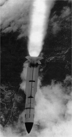
 20 MHz downlink beacon signal from a small spiral antenna at the missile’s rear, caused virtually all the SA-2s launched during a five-day period to lose control. And of the 247 missiles fired between December 14, 1967 and March 31, 1968, only three destroyed USAF jets. One of these was 44 th TFS F-105F 63-8312 Midnight Sun, flown by Maj C. J. Fitton and Capt C. S. Harris, who were both killed. Weasel aircraft could not usually carry QRC-160 pods, as they interfered with the aircraft’s other unique ECM systems. 63-8312 was hit by an SA-2 in its starboard wing, the jet disintegrating ten miles from Hanoi as its Weasel flight ran in towards the city.
Soviet technicians responded to the new jamming threat in two ways. Firstly, they advised the batteries to “track on jam”, homing their missiles at the “cloud” of jamming surrounding the enemy formation. The second tactic was to use lesser-known frequencies available for the “Fan Song”, knowing that Shrikes would thereby probably be tuned to the wrong frequency. US Navy cryptological officer Lt Cdr John Arnold, aboard the guided missile cruiser USS Long Beach (CGN-9) sailing in the Gulf of Tonkin, quickly “cracked” the new command codes and frequencies, however, turning the tables in the Weasels’ favour once again.
As well as suppressing SAM sites via EW jamming, the F-105 Weasel flights could adopt their second, more offensive, role. As the 388 th TFW Tactics Manual described it, this allowed “the Weasel flight to direct its entire efforts to seeking out and destroying SA-2 sites or “Firecan” AAA radars”, rather than just protecting the strike force. This technique was first practiced in southern North Vietnam in 1967, but it was also used in Route Pack 6, particularly during Operation Linebacker II.
Takhli’s first Standard ARM-capable F-105Fs went to the 357th TFS in February 1968, and the squadron made the first combat firing of an AGM-78A (Mod 0) on March 10, destroying a “Fan Song”. Three of the five missiles fired on this occasion failed to guide, however. AGM-78B Mod 1 F-105Gs followed early in 1969, and they continued to support post-Rolling Thunder missions in Laos until the 355th TFW ceased combat operations in October 1970. The Weasels then moved to Korat as Det 1 of the 12th TFS, where they combined with survivors from Takhli’s 44th, 333rd and 354th TFSs. Flying a mixed fleet of F – and G-models, Det 1 subsequently became the 6010th WWS, before being redesignated the 17th WWS on December 1, 1971.
The squadron participated in Operation Kingpin on November 20—21, 1970, when the USAF supported US Army Special Forces in an unsuccessful attempt to rescue PoWs (including 47 EWOs) from Son Tay prison. Five Weasels destroyed four SAM sites in the area, with a fifth one being left in a damaged state. During a later
“protective reaction” strike, F-105Gs used AGM-78s to destroy the Moc Chau radar station that was directing MiG activity over Laos.
When the bombing of North Vietnam re-commenced in April 1972, the 17th WWS was reinforced by Det 1 of the 561stTFS/23rd TFW, which flew in from McConnell AFB, Wichita. The North Vietnamese had massively increased their defenses since Rolling Thunder had ended in November 1968, with the Weasels now facing more than 300 SA-2 sites. An April 16 B-52 mission attracted 250 SAMs, and F-105G 63-8342 was lost as it attacked a missile supply depot. Seven F-105Gs were shot down in 1971—72, six of them by SA-2s as Operation Linebacker took USAF strike packages back to the Hanoi-Haiphong area. In several cases the Weasel crews were just about to fire at “Fan Songs” that were tracking them when SA-2s got them first, two losses arising from missiles suddenly emerging from cloud.
However, the destruction was mutual. During Operation Proud Deep Alpha (December 26—30, 1971) Weasels fired 50 Shrikes and ten AGM-78s, knocking out five “Fan Songs” and at least three early warning radar installations.
Not all ARM launches went according to plan, as Maj Murray B. Denton recalled:
Myself and my “Bear”, Russ Ober, were on a night multi-drop B-52 mission. We had gone to the tanker and were orbiting Nakhon Phanom, waiting for our next time-on – target (TOT). Russ was monitoring the AGM-78. As our TOT approached, I started to accelerate to attack speed, and selected my AGM-45 to monitor it inbound to the target. However, when the Shrike was selected the AGM-78 jettisoned from its rack! We finished the mission and returned to Korat, reporting the lost missile. Base personnel at Nakhon Phanom searched their area for two days and finally found the AGM-78 about eight to ten yards from the wing commander’s accommodation trailer. On inspection, a shorted
![]()
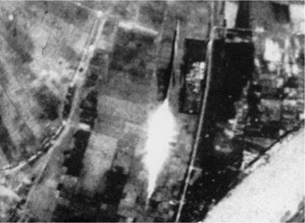
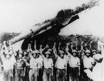
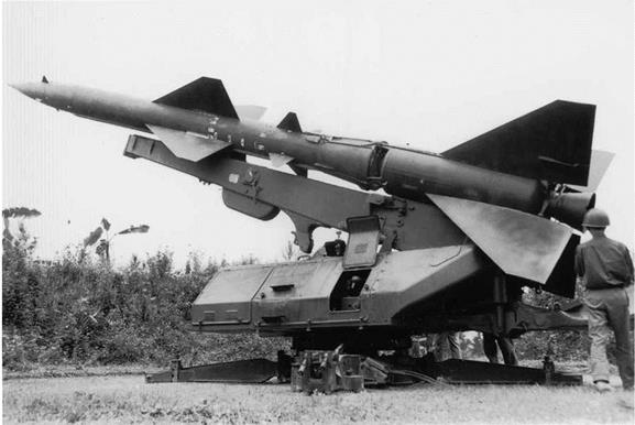
![]() A camouflaged SA-2 trails its distinctively-shaped tail of fire at dangerously close quarters to this gun-camera “automatic photographer”. During Operation Linebacker II six B-52s were claimed by two sites managed by the 57th and 77th Battalions. Some sites salvoed unguided missiles in the hope of achieving a hit. (USAF)
A camouflaged SA-2 trails its distinctively-shaped tail of fire at dangerously close quarters to this gun-camera “automatic photographer”. During Operation Linebacker II six B-52s were claimed by two sites managed by the 57th and 77th Battalions. Some sites salvoed unguided missiles in the hope of achieving a hit. (USAF)
|
|
 |
|
|
|
|
|
|
|
|
|
|
|
|
|
|
|
|
|
|
|
|
|
|
|
|
|
|
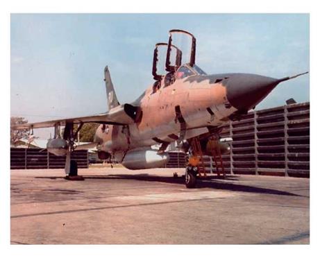
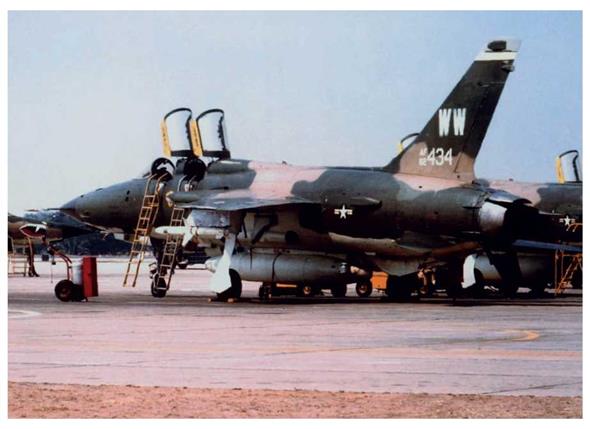
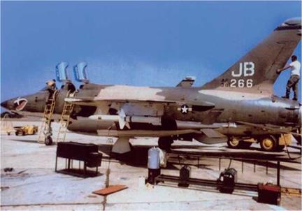 F-105G 63-8266 White Lightning of the 17th WWS/ 388th TFW is prepared for its next mission at Korat RTAFB in August 1972. This unit replaced the 6010th WWS from December 1, 1971, and continued flying combat operations until October 1974, when the survivors returned to the USA under Operation Coronet Exxon. 63-8266 completed another six years with the 35th TFW (visiting Germany in 1976) prior to retiring to the Mid-America Air Museum in Liberal, Kansas, in 1992. (Larsen/Remington)
and corroded connection was found on the AGM-78 pylon. Needless to say, the entire fleet was checked.
As the North Vietnamese moved south, preparing to invade South Vietnam, their SA-2 batteries followed. They shot down a 17 th WWS F-105G (63-8333) from a position just north of the DMZ on February 17, 1972 and an 8 th TFW AC-130A gunship from a SAM site in southern Laos on March 28. Their main objective was to bring down a B-52, and much Weasel time was devoted to four-hour missions protecting the bombers. “Ambush” sites were cleared in difficult terrain under Soviet direction, and batteries would fire a few SA-2s before hiding in the jungle and moving
|
:> |
on to escape detection. After many attempts the SA-2 finally got lucky on November 22, 1972 when B-52D 55-0110 was hit near Vinh. Dan Barry was leading the Weasel flight of four F-105Gs that night:
The B-52 cell was supposed to ingress from the south-southwest, and we put the 17th WWS element on the right side of its ingress track and the 651st element on the left. Since we were usually down at 15,000ft (about 20,000—25,000ft below the “BUFFs”), we never had a visual on the bombers. We operated individually in an orbit to give optimum positioning for coverage based on the B-52s’ TOT. Unfortunately, they were never on our frequency, so we never received any change in TOT or ingress track, nor could they receive any advisory we’d transmit on SAM signals received.
Although at least one 17th WWS crew fired a pre-emptive Shrike, I don’t believe any of us received a “Fan Song” signal. I recall only one SAM being fired, and it seems to go nearly vertical before exploding at altitude. A short time later we began to hear calls on Guard frequency, with “BUFF” crews trying to make contact with one of the jets in their cell. I remember finally turning towards our egress heading and seeing an explosion at altitude and the flaming wreckage falling nearly 100 miles away.
The B-52D had managed to struggle across the border into Thailand before breaking up. All six crewmen were recovered.
As this incident graphically proved, SA-2 crews had learned how to “burn through” the B-52’s considerable jamming power (particularly the less-protected B-52G) by firing in “track-on-jam” mode when the intensity of the jammers was reduced while bombers were directly above the target, or banking away just after releasing their ordnance. This technique helped them to shoot down no fewer than 16 B-52s and damage nine others during the 11-day Linebacker IIoffensive at year-end.
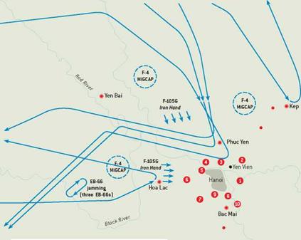
During this intense period of operations the Weasels used their missiles mainly for suppression as they orbited below the bombers. On the first night of Linebacker II, 47 Shrikes and 12 Standard ARMs were launched at some of the 32 operational SAM sites in the Hanoi/Haiphong area, thus keeping B-52 losses to three jets. Nevertheless, 567 SA-2s were fired during the first three nights as the B-52s flew their predictable routes across Hanoi, exposed to SAMs for a full 20 minutes. The first casualty was hit by two SA-2s fired from Nguyen Thang’s 59th SAM battalion. By the fifth night missile stocks had run very low, and the 36-hour “Christmas truce” was the SA-2 assembly centers’ only chance to replenish sites with more than 100 missiles.
Although only three ARMs definitely “killed” radars during the 11-day onslaught, there were 160 occasions on which radars closed down, probably due to Weasel suppression by F-105Gs (with F-4E Phantom II “hunter-killer” support for some missions) flying race-track patterns on either side of the bomber stream. Five sites were seriously damaged by bombs from designated B-52 or F-111A attacks, with another 15 being knocked out by F-105G/F-4E hunter-killer teams. By the last night of the campaign (December 29/30) hardly any SAM radar emissions were detected. Six more sites were hit by F-111s and two by B-52s, including SA-2 assembly facilities 70 near Phuc Yen and Trai Cam.




 aircraft were downed in the final onslaught, including 17 B-52s. The latter was the highest loss figure to SAMs for any USAF type that year, exceeding the 14 losses of the far more numerous F-4 Phantom IIs.


 When Congress finally withdrew funding for military activity in Southeast Asia on August 15, 1973, the 12 F-105Gs of the 561st TFS Det 1 returned to George AFB, California, under Operation Coronet Bolo IV, joining the 35th TFW. The aircraft remained in service with the group until 1978, when conversion to the F-105G’s successor, the F-4G Phantom II began. After 17 Thunderchief years, the 561st TFS’s F-105Gs were passed to the Georgia Air National Guard’s 128th TFS in 1979-80. Following two years of refurbishment, the veteran aircraft flew on until May 25, 1983 when the last 128th TFS Wild Weasel (63-8299) was retired, thus ending 20 years of
 A second unit, the 562nd TFS, was formed at George AFB with F-105Gs of the 17th WWS upon their return from Korat RTAFB in October 1974. This squadron ended the aircraft’s TAC active – duty career on July 12, 1980.


 On both sides, courage and ingenuity were at least as important as technology.

 Spillers via Norman Taylor)
 Republic Aviation had already tested an AN/APS-107 RHAW in an F-105D but rejected it in September 1965 in favor of the Vector IV as an urgent means of reducing the escalating attrition amongst Thunderchief units over North Vietnam. ATI and the Sacramento Air Material Area (SMAMA) successfully completed an installation in F-105D 62-4291 within five days, and a second aircraft was ready on 27 October 1965. This F-105D (61-0138) was fitted with a Bendix DPN-61 homing receiver, a fin-cap radar-warning receiver (RWR) and a SAM threat warning CRT display as the