Category And Colors

Visibility of Jet No. 622 paint in day operations clarified, September 1944

In a letter dated September 11, 1944, the Production Engineering Section (WF) informed the Bombardment Requirements Division (Washington, DC), that there was little difference in the visibility of Jet No. 622 camouflage in daylight from that of an unpainted, bare – metal aircraft. Aircraft seen from the ground were usually darker than the sky, an indication that the gloss black finish would make little difference in daytime.

image350

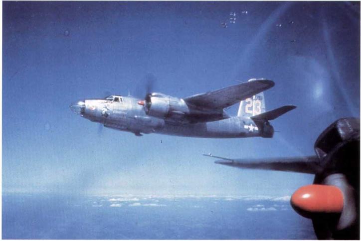
Martin B-26, 42-97783(7), aircraft 23, Yellow, Red propeller bosses. “Thumper II”, of the 441st BS, 320th BG, Twelth Air Force. (TJSAF via Gerry R. Markgraf)

image351

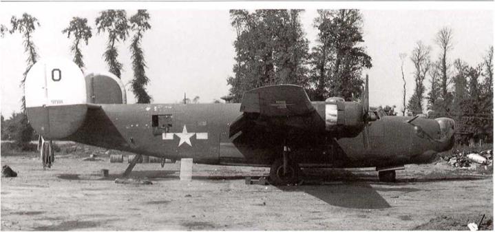
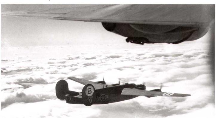
Consolidated B-24H-21-FO, 42-94918, aircraft “O” of 493rd BG, 3rd Air Division, seen at strip A-IO, Carentan, Normandy, on September 26, 1944. In standard dark olive drah and neutral gray finish, the group colors on the outer face of the vertical tails are bottom one-third red, remainder white. This was the last Eighth Air Force BG to become operational, on June 6,1944. It was converted to B-17 aircraft starting in August, 1944, so its use of the B-24 lasted barely three months. (William L. Swisher)

The Jet No. 622 paint added about 150 lbs to the weight of a B-29, but they felt that this would be counteracted by the increased smoothness of the finish,

(B-29s used the gloss black finish while serving with the new Twentieth Air Force in the Pacific – author).

Douglas service document details requirements for Removal of Camouflage and Enamel Finishes, October 1944.

The following document was issued by Douglas in a service bulletin and details what a job it was to remove camouflage finishes from previously painted aircraft, After reading the details, it is obvious why it was not done very often.

image352

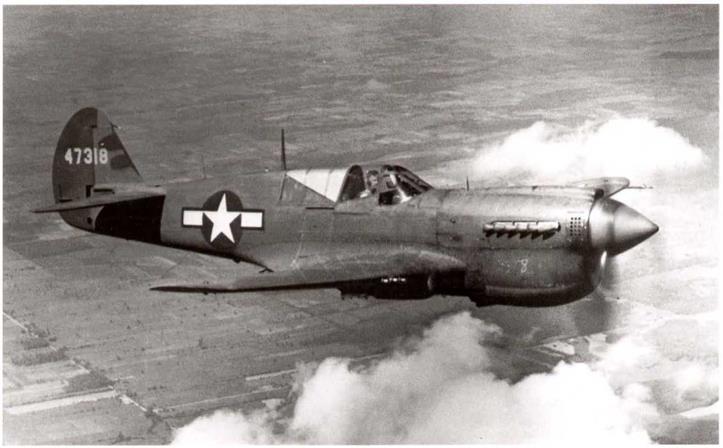
Curtiss P-40N-30-CL, 44-7318, seen in late 1944, still in production! (Nick Williams)

image353

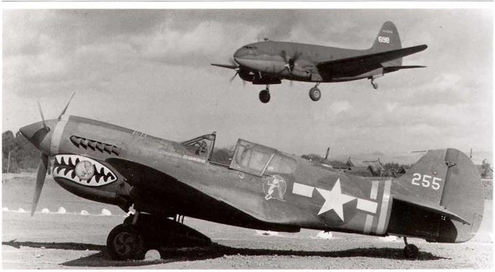
Curtiss C-46A-25-CC, 41-24698, lands at a 14th Air Force field in China late in 1944. In the foreground is Curtiss P-40K-5-CU, serial unknown, aircraft “255” of the Flying Tigers unit. Stripes on the rear fuselage denote a squadron commander. (IISAF)

Stripping. Removal of Camouflage and Enamel Finishes.

Removal of camouflage finishes and zinc chromate primers from metal surfaces is a headache regardless of the process used. The following, however, has the advantage of being less injurious to the metal surfaces and of minimizing work for ground crews.

Materials

1. Turco paint remover (L-713C): This remover is toxic and contains ingredients which are harmful to the eyes and skin. Workmen must be protected from contact with the stripper by wearing caps, goggles, gloves, aprons, and other clothes which will give complete protection.

2. DuPont acetate dope (5306) or acetate butyrate dope (AN-D-1).

3. Cellulose nitrate dope and lacquer thinner (AN-TT-T-256).

4. Ethyl acetate (AN-O-E-758).

5. Kraft wrapping paper (40 pound): The resistance of this paper to the remover may be considerably increased by impregnating it with acetate dope. Run the paper through a container filled with acetate dope (5306) having a viscosity of 45 to 50 seconds (measured by a No. 3 Zahn cup, while the dope is at a temperature of 25°C). Remove all excess dope with a rubber scraper and allow the paper to dry at least 1/2 hour before rolling it up and storing it for use.

6. Scotch masking tape (1- and 2-inch).

7. Waterproof cloth (AAF16094, Type 2, Class A).

image354

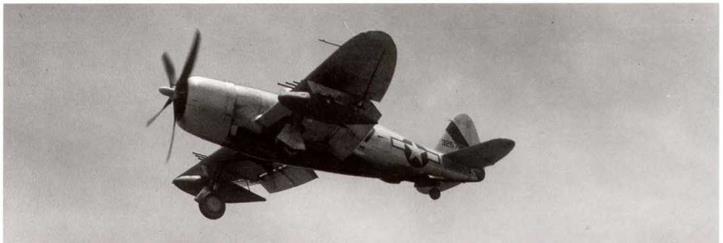
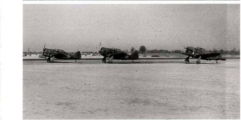
Republic P-47D-23-RA, 43-25753 (the last aircraft of block 23), of the 91st FS, 81st FG, 14th Air Force in China, late 1944. The squadron marking is the black diagonal stripe across the latl(USAF)

image355

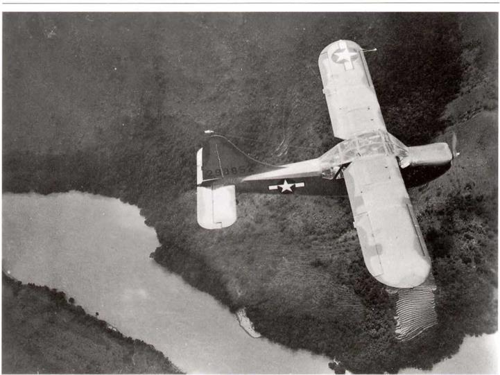
AStinson L-5-VW, 42-98852, is seen over Burma’s very inhospitable terrain. It is still finished with the 1943 medium green blotches, though this is now late 1944. (IJSAF)

GENERAL

Only such markings and identifying insignia as outlined herein will be used on AAF aircraft except as specifically authorized by the Commanding General, AAF.

11. PARTS.

Each part and assembly will be permanently and legibly marked the same number as the drawing number in such lo­cation that it can be read after assembly in the unit. (Refer to Specification No. 98-24105.)

12. DETAIL.

Various detail and code markings for the cockpit, fuselage, oil lines, etc., as required in latest revision of Specification No. 98-24105, will be maintained except that paragraph E-19 need not be complied with on airplanes to which fluid line iden­tification decals were not applied in production. In addition, Jet No. 622 finishes (on metal and wood) surfaces will be stenciled in yellow on an upper surface with code number of the approved Jet 622 of the paint manufacturer under the two applicable specifications (Bulletin 102 for lacquer, and 148 for enamel), two dashes, followed by the symbol for the material as “L-29” or “E-3.” Example: D-800-L-29.

13. RADIO CALL NUMBERS.

a. Radio call numbers of not less than four numerals will be maintained on all AAF aircraft, except as stated in paragraph 17.c„ utilizing both sides or each outboard side, as applicable, of the vertical stabilizer and rudder assembly. These call numbers, or designators, will be of a size discernible at a distance of 150 yards. The suggested size is 8 x 12 inches. They will be derived by deletion of the first numeral of the serial number (4) and the hyphen (-), and the combination of the remaining four or more numerals. In case of serial numbers of type 41-7, use zero as necessary to make four numerals, as 1007. Colors will be black for uncamouflaged surfaces, and yellow for camouflaged surfaces except that jet camouflaged planes will have insignia red call numbers. Decaicomania are authorized if available.

b. On all airplanes operating solely within the continental limits of the United States the radio call numbers will also be placed with the top forward on the lower surfaces of wings, except as stated in paragraph 17.g. The size of the number to be painted on aircraft and the matter of whether the numbers will be painted on the left wing only or both wings, will be determined by the local using agency in accordance with the space available and the desired usage. However, the suggested method is to apply 16 x 24 inch numerals on the lower left wing.

c. Radio call numbers in neither location are required, however, on primary trainers not equipped with radio and which bear field identifying numbers.

14. PROPELLER MARKINGS.

American propeller blades, design Nos. A-2721107, A2891100, and A2891106, used in sets in Aeroproducts propellers and design Nos. С-27212Ш) and C-3821306, used in sets in Curtiss propellers, respectively, will be identified by a yellow stripe, 3/8 inch in width and 3/8 inch inboard of the yellow tip. A. O. Smith propellers, design No. Prefix “SPA” used in sets in Curtiss propellers will be identified by two 3/8-inch yellow stripes; one 3/8 inch inboard of the yellow tip, and the other stripe 3/ 8 inch inbdard front the first. These stripes will extend completely around the blade section. The stenciled markings between the 18- and 24-inch stations on the cambered side of the propeller blades wilt be retained. When the exact location of the blade reference station is known, a stripe of yellow paint 1/8 inch wide, 2 inches long, and spaced equally distant between the leading and trailing edge of the blade, will be placed on the thrust face at the reference station.

CAUTION Unless the exact location of the reference station on the blade is known no attempt will be made to identify

this location by the afore-mentioned stripe.

COLORS FOR TRAINING AIRPLANES

a. Advanced Trainers: Aluminized finish except all-metal types, which will be natural metal finish,

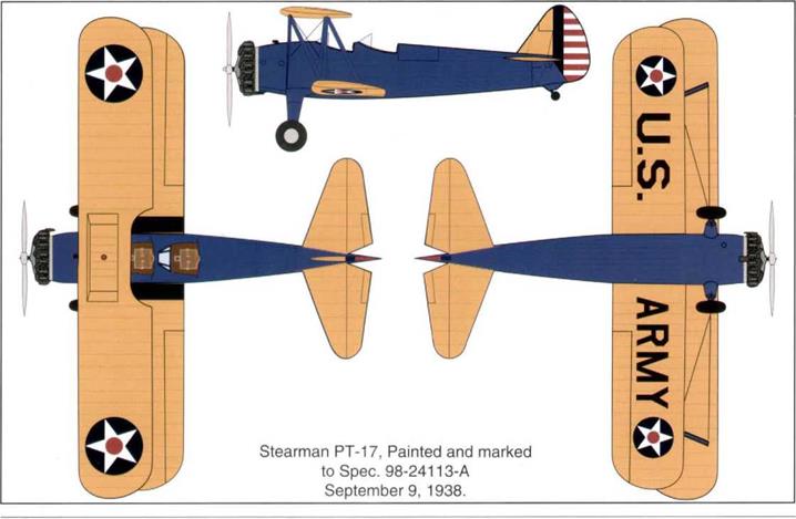
b. Primary and Basic Trainers: Yellow and blue as required by Spec. 98-24113.

2. IDENTIFICATION NUMERALS FOR TRAINING AIRPLANES

a. The use of field numbers and the painting of ring cowls (or combination thereof) for identification purposes of Training airplanes at activities of the various Army A, C. Training Centers and Civil Flying Schools is authorized. Designation of these identification numbers and ring cowl colors for activities within each Training Center will be the responsibility of the respective Commanding General thereof. The identification numbers will be of a contrasting color, preferably block type, and will be applied to each side of the fuselage approximately midway between the vertical projections of the trailing edge of the wing and the leading edge of the horizontal stabilizers. The height of the identification numerals will be approximately three fourths of the projected height of the fuselage at this location.

image23

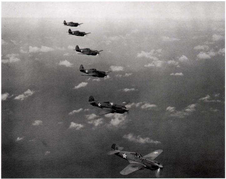
Six Curtiss P-40Cs of the 18th PG over Oahu, Hawaii, on August 1, 1941. The group consisted of the 6th, 19th, 44th, 73rd, and 78th PS. All, except the 44th PS, were caught on the ground on December 7,1941. Aircraft seen are numbered 41,47, 51,53, 54, and 43. (USAF)

3. COLORS FOR USE ON AIRPLANES IN ALASKAN DEPT. OR COUNTRIES HAVING SIMILAR CLIMATIC AND TERRAIN CONDITIONS.

a. To provide a color scheme offering marked contrast for spotting forced landings, etc. for airplanes operating in Alaska or in countries where like conditions prevail, the use on the top and bottom surfaces of wings of camou­flage materials, of the shades covered in A. C. Bulletin No. 41, to best meet the conditions of local terrain color is authorized. Since the distribution of airplanes is not known at the time the respective manufacturers are camouflaging the finished airplanes, airplanes will necessarily be furnished with camouflage in accordance with A. C. Spec. 24114. It will therefore be necessary to apply any special colors where such special distinguishing colors are authorized. It will not be necessary to remove the original camouflage coating to apply the special colors. However, lacquer camouflage material cannot be applied over a previous coating of enamel camouflage material.

b^ When tactical requirements demand, airplanes operated in these locations will be maintained in a camouflaged condition as follows:

(1) Lower surfaces will be camouflaged as prescribed in A. C. Spec. 24114.

(2) Upper surfaces will be camouflaged with such shades of specified materials as best blend with the local terrain.

5, MARKINGS. – a. Each airplane and each lighter-than-air aircraft will be marked in accordance with Spec. Nos. 98­24105 and 99-2050, respectively.

b. The code markings specified therein are the means by which the number, identity, and age of protective coatings of the airfoils, fuselage, etc., and other pertinent data relating to the aircraft, are determined. Therefore, in no instance will such marks be omitted or placed where they can not readily be seen when the aircraft is completely assembled.

c. Markings required by specifications will neither be altered nor effaced, except as required by repairs or refinishing operations, in which case the markings will be properly replaced, nor will they be transferred from locations designated in specifications.

d. Подпись: ■
There being no military reason for the use of individual names, the practice of naming airplanes after states, municipalities, or other localities will be discontinued. However, each airplane will have the name of the home station, in a contrasting color, placed on the left side of the fuselage immediately above the technical data legend using letters approximately one inch high, with the top of the letters toward the leading edge of the wing. These markings are to be centrally located with respect to the wing outline. The letters are to be of the vertical type, 24 inches high and with strokes four inches wide.

image24

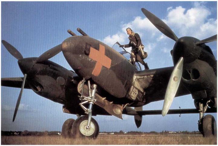
Lockheed P-38D, 5-1P, showing the red cross used in the 1941 Louisiana maneuvers. It carries the name “Snuff" on the nose in white. Note the unpainted propellers. (USAF via Gerry R. Markgraf)

image25

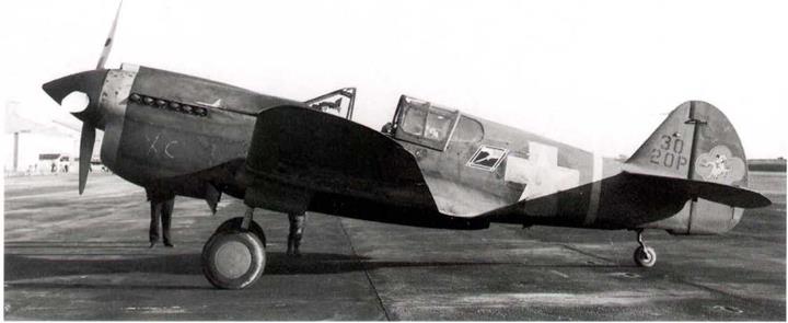
Curtiss P-40E of the 79th PS, 20th PG, Hamilton Field, at Oakland on December 6,1941. This is the Flight Leader’s aircraft, A Flight. The nose band and command stripe are in yellow no. 48. Propeller is still not camouflaged black, as ordered in May 1941. Fuselage cocarde is covered with a maneuver cross. The personal insignia on the rudder is a major exception to USAAF practice at that time. (F. Shertzer via William L. Swisher)

6, STANDARD INSIGNIA. – Air Corps standard insignia will be placed and maintained on each aircraft, as prescribed in Spec. 98-24102, or Spec. 24114 (camouflaged Airplanes),

7. ORGANIZATION INSIGNIA. – a. Definition. – Organization insignia are those designs, markings, etc., that have been approved by the War Department for use by an individual organization.

b. Rules governing Design, – The following rules govern the designs of Air Corps organization insignia:

(1) They will be simple and, where practicable, will depict some historical significance associated with the

organization,

(2) They will be dignified and in good taste. Fantastic designs may be characteristic and “funny” but have no permanent value.

(3) Each design w ill possess the clearness required to make it distinguishable at a distance of at least 150

yards.

(4) They will not contain —

Numerals

The letters “U. S.”

The Air Corps insignia.

The United States flag.

The United States coat of arms or any part of it.

The complete coat of arms of any state or country, although devices may be taken from them when applicable.

Outlines of geographical maps.

Foreign decorations (e. g, Croix de Guerre, Fourragere).

Campaign ribbons.

c. Submitting Samples for Approval. – Before placing a new design on equipment, three 8 by 10-l/2inch sample copies will be prepared on good quality paper and submitted, for approval, to the Adjutant General through the Chief of the Air Corps. The samples will be colored with water colors or wax crayons in the colors intended for the insignia when placed on the aircraft. Blends of color may be used when essential, but much better results are obtained when blends are not employed, as it is difficult to match or keep them uniform in shade or tint in each of the paintings on the several aircraft. The “poster” type of design and “block” coloring are recommended. A brief outline of the historical development or significance of the design will accompany the sample copies when submitted for approval. No variation from an approved design will be permitted without authority from the Adjutant General,

image26

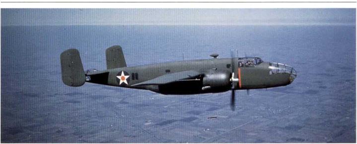
North American B-25Aon test flight over Los Angeles in pristine camouflage: note the red warning stripe in line with the propellers. (USAF via Gerry R. Markgraf)

d. Rules Governing Use. – The following rules govern the use of organization insignia on aircraft:

(1) Each aircraft assigned to a permanent organization, including U. S. Army A. C. schools, but not including Civil Flying Schools under contract, will bear the insignia of that organization, For example:

Aircraft assigned to a squadron will bear the insignia of that squadron.

Aircraft assigned to a headquarters of groups, wings, etc., will bear the insignia of such headquarters.

(2) No aircraft will bear organization insignia other than that of one organization.

(3) The placing of organization insignia on aircraft will be a responsibility of the organization to which the insignia pertain. Depots will not be required to reproduce insignia or other markings peculiar to an individual organization.

e. Location, Size, and Application for Airplanes, –

(1) It is impossible to specify a standard location for organization insignia on all airplanes; therefore, no specific locations are mandatory, However, the sides of the fuselage midway between the wings and tail surfaces are the most desirable and should be used whenever conditions permit, so that the insignia on the majority of airplanes will be in the same relative location. The spaces selected on the two sides of the fuselage should be as nearly as possible opposite each other, and should have smooth surfaces unbroken by fittings, lacing, fasteners, steps, joints, openings, etc. When avoidable, insignia will not be placed on cowling.

(2) In no instance will the size of an insignia exceed three fourths of the depth of the fuselage at the point at which the insignia is applied. Otherwise, the size will be governed by the most suitable spaces available, provided that such spaces are not too small or unfavorable for other reasons. If the available spaces are too small to provide visibility, as described in paragraph 7 b (3), or is unsuitable due to fittings, lacings, fasteners, etc., or corrugated metal, each insignia may be painted on a sheet of aluminum or suitable alloy of the desired shape and area and not more than 1/32-inch thick. All sharp comers and edges of such sheets will be rounded off. The sheets will then be secured to the sides of the airplane with screws, washers, and nuts, or by other suitable means, in a manner permitting ready removal when necessary. Each sheet will be secured at a sufficient number of points to prevent it being torn off in flight, and to prevent vibration that would cause it to crack or to wear the fabric or other parts. Whenever practicable, it will be secured to rigid members of the airplane. When necessary to attach such a sheet to fabric, the fabric will be adequately reinforced with tape securely attached by doping, and, if required, by stitching. In addition, suitable reinforcing strips of sheet metal or wood will be used next to the inside face of the fabric to receive the inside ends of the screws or other securing parts. Insignia on tike models of airplanes in the same organization should be uniform in size.

f. Location. Size, and Application for Lighter-than-Aircraft.

(1) Organization insignia will be placed on each-side of each lighter-than-aircraft. The locations for observation balloons will be on each side, halfway between the greatest diameter and the leading edges of the horizontal lobes. The locations for spherical balloons will be at points in line with and three feet from each end of the wording “U. S. Army.”

(2) In no instance will the size of lighter-than-air insignia exceed nine square feet. The insignia placed on each craft assigned to an organization will be uniform in size. However, this does not require that insignia of different organizations be of the same size.

(3) The insignia for all lighter-than-aircraft will be painted on two-ply envelope-fabric. Code No. IOI, and securely attached to the envelope with rubber cement. Each sheet of fabric will be neatly trimmed to the minimum size

image27

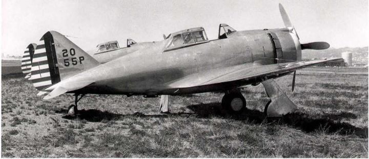
Republic P-43 (41-6674) of the 55th PG at Oakland in 1941. It was not camouflaged yet, because it was considered to be an interim type, not suitable for combat use overseas. The nose cowl is painted white. (F. Shertzer via William L. Swisher)

required, and, to insure adhesion, corresponding areas of the aluminum finish will be carefully removed from the envelopes with suitable wire brushes.

g. Decalcomania Insignia. – Where personnel are not available to paint organization insignia in a satisfac­tory manner, the use of decalcomania insignia on airplanes is authorized. Owing to the local nature of their usage, however it will be necessary for stations desiring to use these transfers to obtain them by local purchase. Their application does nol require skilled workmen, and when coated with clear varnish after being applied, they are about as durable as the average painted design. The cost varies with:

(1) Size

(2) Design

(3) The number ordered

(4) The number of colors and to some extent the colors themselves

Instructions for applying decalcomania are furnished by the manufacturer. Until used, the transfers should be stored in a dry place where they will not be exposed to temperatures abovenormal.

8. ORGANIZATION IDENTIFICATION. – as a means of identifying airplanes, allairplanes will be marked as outlined herein. These markings (paragraphs 8, 9, and 10) are in addition to the standard markings, insignia, and technical data prescribed in paragraphs 5, 6, and 7, and will be applied by the organization to which the airplanes are assigned,

a. Squadron Recognition Colors. – A suitable depth of the front portion of engine nacelles will be painted as follows:

(1) Pursuit. Attack and Bombardment Squadrons. – The cowling will be painted one solid color: red, white, blue or yellow. The assignment of colors will be made by the group commander except where, as a citation for distinguished service, an individual squadron may be authorized by higher authority to use other recognition markings.

(2) Group Headquarters and Headquarters Squadrons. –

(a) 3-Squadron Group. – The cowling to be divided by longitudinal lines into

three equal segments; one segment to be painted red, one white, and one

yellow,

(b) 4-Squadron Group, – The cowling to be divided by longitudinal lines into

four equal segments; one segment to be painted red, one white, one yellow, and one blue.

(3) Reconnaissance Squadrons.- The color or color combinations for painting

the cowling to be specified by wing commanders.

(4) Hq. Squadrons of Wings. Air Bases and G. H.O. AinForce, – No recognition colors to be employed.

image28image29

Pursuit, Attack and Bombardment Squadrons,
Assignment of Colors in Group.
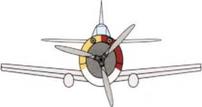
image30image31

Group Headquarters and Headquarters Squadrons.

image32

Squadron Command Airplanes


image33

A1 Flight Command Airplanes


image34

‘C Flight Command Airplanes


image35

Republic P-43s of the 1st PG at the August 1941, Carolina maneuvers. Aircraft numbers 70, 73, and 74 of the group, they have finally been camouflaged, and carry the usual maneuvers red fuselage cross over the cocardes. (USAF)

image36

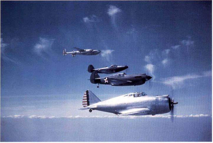
Republic YP-43, Curtiss P-40B, Bell P-39C and the second Lockheed YP-38 show the aircraft that had been selected in the Air Corps 1939 competition. The YP-38 and YP-43 are in natural metal and the P-39 and P-40 are camouflaged to Spec. 24114. In the event, all of these types proved to be disappointing performers, only the P-38 surviving in front line service until the end of the war. (LSAF via Gerry R. Markgraf)

b. Airplane Designators.

(1) Each airplane will have a distinctive designator assigned, which will consist of a combination of letters and numbers except airplanes on loan to civil flying-schools engaged under contract to train student Army pilots. The system of assigning the designators will use first the wing, group, squadron, corps area, or other unit identifying number, wherever applicable. This number will be followed by a letter or letters designating the type of equipment, as “B” for bombardment, “P” for pursuit, etc., or if not applicable, the assignment of the airplane as “W” for wing, “AB” for air base, “OR” for organized reserve, “AD” for air depot, etc., followed by a number which will be assigned by group and station commanders or by higher authority to designate a particular airplane. The following outlines the lettering system to be used,

image37

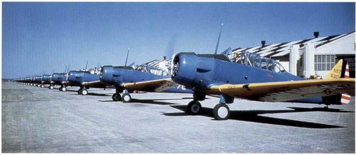
Colorful lineup of approximately 20 North America BC-ls. The nearest aircraft is marked 557 over 53ED on the tin. They are finished in the A­N gloss true blue and gloss orange yellow colors. (USAF)

Activity

Svmbol

Air Base

AB

Air Depot

AD

Air Officer

AO

Bombardment Group

В

Communication Squadron

C

Headquarters

HQ

Instructor (miscellaneous)

IM.

Materiel Division

MD

Miscellaneous

M

National Guard

NG

Observation.

0

Organized Reserve

OR

Photo

PH

Pursuit Group

P

Reconnaissance

R

School

ED

Staff

S

Technical Supervisor

TS

Transport

T

Wing

w

Weather (Observation)

wo

(2) The following are examples of complete designators:

Activity Designator

Headquarters Squadron, GHQ Air Force HQ1 to HQ –

Headquarters Squadron, 2nd Wing 2W1 “ 2W –

5 th Air Base Squadron 5AB1 “ 5AB –

5th Bombardment Group.

9B1

it

9B-

20th Pursuit Group

20P1

tt

20P-

41st Reconnaissance Squadron

41RI

tt

41R –

4th Composite Group

4MB1

tt

4MB-

5 th Transport Squadron

6T1

tt

6T-

Fairfield Air Depot

FAD1

it

FAD-

Middletown Air Depot

MAD1

U

MAD-

Southeast Air Depot

SEAD1

tt

SEAD –

San Antonio Air Depot

SAADI

it

SAAD-

Sacramento Air Depot

SADI

SAD –

Panama Air Depot

PAD1

tt

PAD-

Hawaiian Air Depot

HADI

tt

HAD-

Phillippinc Air Depot

PHAD1

tt

PHAD-

2nd Corps Area Air Officer

2A01

tt

2AO –

1st Communications Squadron

1C1

it

1C-

National Guard Instructors

1M1

tt

Ш –

154th National Guard Observation Squadron54NGl Materiel Division

“ 54NG – MD1 “

MD –

22nd Observation Squadron, Air Corps

2201

tt

220-

1st Photo Squadron

1PH1

tt

1PH-

8th Corps Area Organized Reserve

80RI

tt

80R –

63rd School Squadron

63ED1

tt

63ED-

1st Staff Squadron

1S1

tt

IS-

Technical Supervisor

TS1

tt

TS-

2nd Weather Observation Squadron

2W01

tt

2WO-

Miscellaneous

Ml

tt

M –

* NOTE: Not inducted into Federal Service – All National Guard Squadrons are Observation, and with the NG symbol used it is not necessary to add the О symbol. Since all National Guard Units bear a squadron number between 100 to 199, the hundred designation will be dropped in the interest of brevity.

After induction into Federal Service – Federalized National Guard squadrons will use designators as specified for Air Corps Observation Squadrons, including the О symbol and the complete squadron number.

(3) In the case of a composite group, the airplane designator will consist of the group number, followed by the letter “M” for miscellaneous, a second letter to indicate the type of equipment, as “B” for bombardment, and the designating number of the particular airplane.

c. The letters and figures composing the airplane designators will be of the vertical block type, the width will be 2/3 of the height and the strokes will be approximately 1” wide for every 6" of height. The distance between the letters is equal to 1/2 the width of a letter. In consideration of the varied sizes and configurations of airfoils and fuselages of A. C. airplanes, it is impractical to specify a standard height of letters that will meet the requirements all airplanes. In general, however, the height of the letters and figures will be as specified in the following paragraphs and uniformity should be maintained for airplanes of similar types at a station. The airplane designators will be painted on in a centrally located position in the following locations:

(1) For airplanes not camouflaged. – The designator will appear on each side of the vertical stabilizer.

Where more than one vertical stabilizer is used, the designator will appear on the left exposed side of the left hand stabilizer and on the right exposed side of the right hand stabilizer. The lettering will appear in two lines with the individual airplane number on the top line, and the unit or organization designator on the bottom line and reading from left to right. For example, 12 indicating number “12” airplane of the 31st Pursuit Group. The letters and airplane numbers will be of sufficient height as to make the designator readily discernible from a distance of approximately 150 yards.

(2) For camouflaged airplanes. – The designator will be as specified in paragraph 8 c (1) for uncamouflaged airplanes, except that the necessary area of both the vertical stabilizer and the rudder be utilized.

(3) On the upper and lower sides of the left wing only (upper side of the left upper wing and the lower side of the left lower wing in the case of a biplane). The lettering will appear all on one line, with the top of the letters toward the leading edge.

(a) The upper surface markings will be centered on a line at right angles to the longitudinal axis of the airplane, and passing through the center of the Air Corps insignia. The height of the letters will be 1/5 of the chord of the wing, as measured at a point 3/4 of the distance from the fuselage to the inner edge of the Air Corps insignia.

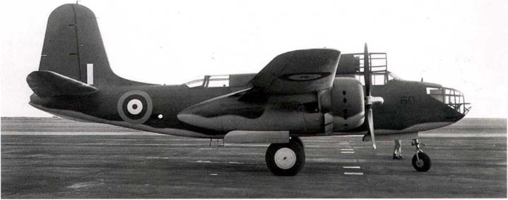
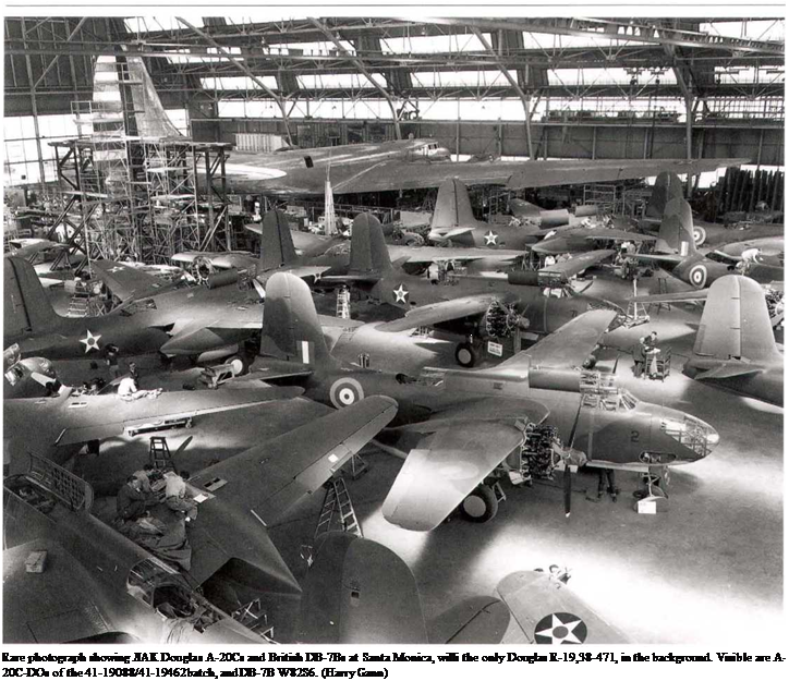
Подпись: Rare photograph showing ЛАК Douglas A-20Cs and British DB-7Bs at Santa Monica, willi the only Douglas R-19,38-471, in the background. Visible are A-20C-DOs of the 41-19088/41-19462 batch, and DB-7B W82S6. (Harry Gann)

(b) The lower surface markings will be ahead of and parallel to the word "Army.” The height of the letters will be 1/3 of that portion of the chord from the top of the letters composing the word "Army” to the center of the leading edge of the wing, as measured at a point 3/4 of the distance from the fuselage to the inner edge of the Air Corps insignia.

(4) In addition to the above, the airplane identification number (squadron, group or station) “12” in ex­ample cited in paragraph 4 с. (1), will be painted on the engine cowling, or on the forward portion of the fuselage, so as to be visible from the forward hemisphere. The variation in size and contour of the locations available for these identifying numbers will necessitate that the exact location and size of the numbers be determined locally for each model of airplane.

(5) The following colors will be used for these identifying markings.

(a) Black against a light background. In the case of camouflaged airplanes black, shade No. 44, Air Corps Bulletin No. 41.

(b) Yellow (Shade No. 4 for uncamouflaged airplanes – Shade No. 48, A. C. Bulletin No.4l, for camouflaged airplanes) against a dark ground.

image39

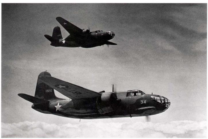
Douglas A-20C-DO, 41-19210, in formation with another. This was the AAF version of the RAF Boston Mk. III and was finished in the standard RAF day bomber camouflage of dark green and dark earth over sky. 808 were built at Santa Monica and 140 at Boeing, Seattle. (USAF)

9. COMMAND RECOGNITION STRIPES. – Command airplanes, except as noted in paragraph 9 c, will be identi­

fied by painted stripes 5 inches wide, encircling the fuselage immediately back of the rear cockpit. These stripes will be of the same color as the squadron identification color, except that black will be used instead of blue on blue or camouflage fuse­lages, and instead of white on unfinished aluminum alloy fuselages. The number of stripes and their position on the fuselage will be as follows:

a. Squadron Command Airplanes. – Two stripes, five inches apart, encircling the fuselage in planes at right angles

to the axis of the airplane.

b. Flight Command Airplanes. –

A flight – One stripe encircling the fuselage in a plane at right angles to the axis of the airplane.

В Flight – One stripe encircling the fuselage at a 45° angle from the horizontal with the uppermost part of

the encircling stripe inclined toward the front of the airplane.

C Flight – One stripe encircling the fuselage at a 45° angle from the horizontal with the uppermost part of

the encircling stripe inclined toward the rear of the airplane.

c. Command identification stripes will not be employed by headquarters squadrons of

Air Bases, Wings, or the G. F1.Q. Air Force.

10. NAMES OF COMBAT CREW. – a. Door Type Airplanes. Names of permanently assigned members of the combat crew will be posted on the inside of the door. For a this purpose, a metal holder with celluloid cover, size approximately 5" x 7", containing a typed list of the combat crew will be utilized.

b. Cockpit Type Airplanes – Names of permanently assigned members of the combat crew to be stenciled or painted on the forward portion of the left side of the fuselage; letters to be approximately 1/2” in height; white, and on a black, rectangular background of suitable dimensions.

11. PAINTTQBEUSED.

a. On airplanes not camouflaged – – All painted insignia, organization identification colors, etc., enamel, Spec. 3-98, insignia colors in oil, Spec. 3-120, or lacquer, Spec. 3-158, will be used.

Jr. On camouflaged airplanes. – The only paints, regardless of the purpose for which used, that will be applied to the exterior surface of camouflaged airplanes, will be Air Corps camouflage materials, (Spec. Nos. 14105,14106 or 14109) and of colors covered by Air Corps Bulletin No. 41. Primer, metal, zinc chromate, Spec. 14080, will be used wherever a primer coat is required.

image40

Douglas DB-7B, RAF Boston 111 (RAF serial number W8311) at Oakland in 1941, showing the RAF day bomber camouflage of dark earth and dark green over sky. 836 of this version were supplied to the RAF. (William L. Swisher)

image41

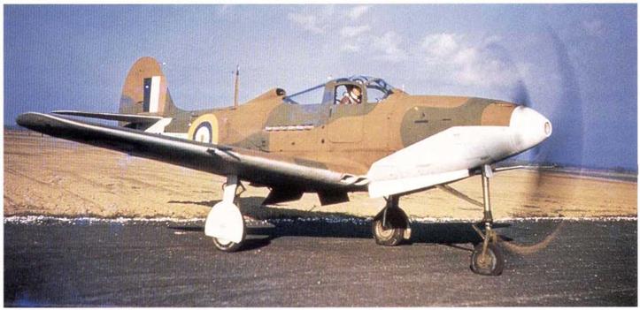
Beil Airacobra Mk 1 for RAF, AH62I, running up, shows its incorrect application of RAF fighter camouflage. The Dark Earth and Dark Green should come down to lower edge of nose and fuselage, not brought up to the center-line as seen. Sky was the underneath color. (USAF via Gerry R. Markgraf)

Camouflage Finishes for Aircraft (Specification 24114)

Anew Air Corps Spec. 24114 “Camouflage Finishes for Aircraft”, was issued as a result of the Air Corps Study No. 42 on camouflage of combat aircraft. Dated October 24, 1940, it also introduced Air Corps Bulletin No. 41, “Color Card for Camouflage Finishes”, (see Chapter 7) which established the new Air Corps matt colors for permanent camouflage paints. The key requirements of this specifica­tion were:

Application-

One coat of zinc chromate primer, Spec. 14080, shall be applied to all exterior surfaces. This shall be followed by two coats of camouflage lacquer, Spec. 14105, applied as follows: all upper surfaces except for insignia shall be coated with dark olive drab, Shade 41 of Bulletin 41, camouflage lacquer. The olive drab coating shall extend downward on the sides of the fuselage and all other similar surfaces in such manner than none of the neutral gray coating is visible when the airplane is in normal level flight attitude and is viewed from above from any direction within an angle of approximately thirty degrees from vertical lines tangent to the airplane. The location of the color boundary line in accordance with the foregoing shall be subject to the approval of the Procurement Agency. All under surfaces, except for insignia and markings, shall be coated with neutral gray, Shade 43 of Bulletin 41, camouflage lacquer. Masks shall not be employed to separate the two shades. The lines of demarcation shall be eliminated as far as possible by blending the colors at the junction line by over-spraying.

Finish of Fabric Covered Surfaces:

Apply at least three brushed coats of yellow or cream semi-pigmented nitrate dope. The dope shall not be thinned for brush application. Apply at least one spray coat of yellow or cream semi-pigmented nitrate dope, thinned as required for spray application. Apply at least two spray coats of dark olive drab or neutral gray fully pigmented nitrate camouflage dope as required.

image42

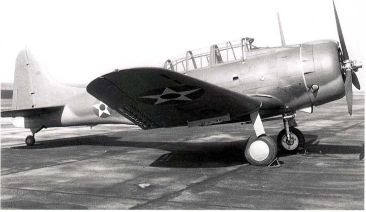
Douglas A-24 at Oakland in 1941. Three inch high letters on the tail show that this an SBD-3A (for Army) taken off the Navy line. Aircraft lacks the Navy arresting hook and has a pneumatic tire on the tail wheel, rather than the solid Navy tire. It is finished in dark olive drab and neutral gray, per Douglas finish drawing. (William L. Swisher)

Spec. No. 24114-A, Camouflage Finishes for Aircraft issued September 4,1942

The various changes discussed in the preceding pages made it necessary to revise Spec. 24114 and the revised – Aversion was released on September 4, 1942. The major changes were:

Application. – One coat of zinc chromate primer was now required to be applied to all exterior metal surfaces. This was to be followed by one of two types of camouflage finishes as follows:

All exterior metal surfaces (except for insignia and markings) were to be coated with two coats of camouflage lacquer or with one coat of camouflage enamel.

The entire airplane was to be coated with either lacquer or enamel. In no case was lacquer to be used for upper surface and enamel for the lower surface or vice-versa,

The splotches referred to earlier were now called out, as was the overspray at the color boundary lines.

If specified, the upper surfaces could be coated with Medium Green, Shade No. 42; White, Shade No. 46; or Sand, Shade No. 49, in lieu of the usual Dark Olive Drab Shade No. 41 (note: this was the first use mentioned of the new Sand Shade No. 49, rather than the earlier Sand No. 26).

All under surfaces were to be painted Neutral Gray Shade No. 43, or if specified, Black, Shade No. 44.

Note re Camouflage and Air Defense of American Installations, AAF Chief of Staff, September 9,1942.

The following very interesting note was written to the Corps of Engineers, by the Chief of Staff, USAAF, on September 9,1942:

1. If and when the German offensive in Russia is completed there will be a concentration of German aircraft on the Western Front. When this occurs, more intensive German bombing activities can be expected against American airdromes and American installations. Fullest measures should be taken for the camouflaging of installations of the VIII Air Force Service Command and steps should be taken to ask for proper units for air defense. It is desired that your section restudy camouflage or air defense requirements with the above in mind and report to this office any change which you recommend.

This is a graphic reminder that the future course of the war in Europe was anything but certain in view of the then power of the Third Reich.

image154

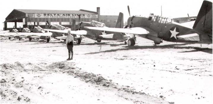
Vultce Vengeance Mk. Us awaiting conversion to the target towing role for the AAFat Delta Air Lines, Atlanta facility. Serial no. on the nearest aircraft is AN59? (Delta Air Lines via Talbott)

image155

Another view of the Vengeance Mk. IIs at Delta Air Lines for conversion. More than 18 can be seen in this photograph. Only visible serial no. is AN594. (Delta Air Lines via Talbott)

image156

Spec. No. 98-24113-A, amendment No. 6, September 12,1942, completely deletes blue and yellow finishes for trainer aircraft.

This revision to Spec. 241I3-A, “Color for Army Air Corps Airplanes,” finally caught up with the times and changed its title to read “Colors for Army Air Forces Airplanes.”

Of greater substance, it finally deleted all requirements for blue and yellow finishes for trainer aircraft, and stated that color requirements for camouflaged aircraft were to be in accordance with Spec. No. 24114. The finished color scheme for painted surfaces was to be as follows for the parts listed:

image157

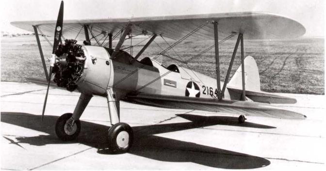
Stearman PT-17-BW, 42-16421, is seen in the all-aluminum finish adopted in September 1942, replacing the true blue and orange yellow scheme. 3,064 of this version were built. (Harry Gann)

Spec. No. 24114-A, Camouflage Finishes for Aircraft issued September 4,1942

Exterior (Exposed) Surfaces.

Wings and Control Surfaces, Including

Подпись: Optional Optional Подпись: Yellow Green (2) Floor and sides to tops of windows - Dull dark green. Sides above window and ceiling - Aluminum Dull dark green Dull dark green and aluminum as specified for closed cockpits. Yellow Green (2) Ribs, Spars, and all interior structures Fuselage, excepting compartments for personnel, luggage and cargo Cockpits for pilots and observers which
are open or for which sliding enclosures arc provided

Closed cockpits, the top and sides of

which form part of the fuselage structure

Seats and upholstering for seats, carpets, drapes, etc.

Passenger compartment (transport airplanes)

Luggage, cargo and bomb compartment

Notes: (1) Aluminum: see Spec. No. 98-24113-A, dated September 9, 1938.

(2) Yellow green shall be prepared in accordance with spec, no. 3-100.

Gen. Arnold queries U. S. Air Forces Commanders world-wide as to value of camouflage on airplanes. Urgent Secret teletype used, March 27, 1943

Gen. Arnold was taking a keen interest in the use of camouflage on the AAF’s combat aircraft and wanted to find out if the various USAAF Commanders world-wide would accept the deletion of camouflage on all airplanes except transports. He asserted that the airplanes would gain about twenty to twenty-five miles per hour in speed without camouflage.

image191

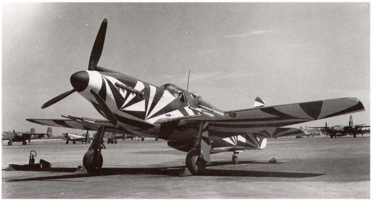
North American P-51A, serial unknown, shown in the special confusion camouflage scheme developed at Eglin Field. Painted in insignia white and insignia blue, except for O. D. on upper surfaces and fuselage top. It is seen in the hangar at Eglin Field. (USAF)


image192

Another view of the finished P-S1A, showing the four 20min cannon in the wings of this early version. (USAF)


image193

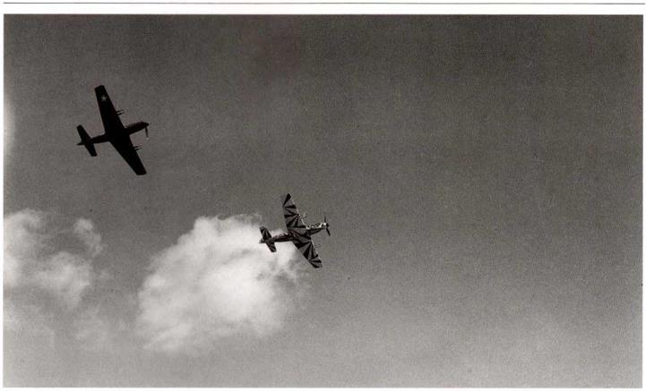
In-flight view of the confusion camouflaged P-51A in formation with a normally finished neutral gray P-S1A. The flight tests showed no advantage over the normal camouflage. (USAF)

Eglin Field issues report on Test of Confusion Camouflage for Fighter type Aircraft, March 27, 1943

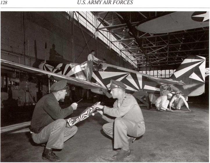
In its continuing tests of various types of camouflage for aircraft, Eglin Field revisited the use of confusion camouflage for fighter type aircraft. They ran these tests on a P-51 A aircraft painted in a disruptive scheme of insignia blue and white chevrons. This scheme was applied to both sides of the fuselage and the vertical tail and all lower surfaces of the P-51, but not to the top of the fuselage or the wing and horizontal tail surfaces. For the purposes of the tests no star insignia or radio call numbers were used on the aircraft.

The results, reported in document 3-43-29, dated March 27, 1943, showed that the disadvantages of the scheme far outweighed any possible advantages, and the report recommended that no further use be made of this type of camouflage. (Note: this was a replay of similar testing done by the Air Corps Board in Study No. 42 and came up with the same negative results. See author’s volume on the Air Service and Air Corps).

Camouflage materials change for Douglas C-54A, ordered April 9,1943.

Douglas Aircraft was told to change the camouflage finish materials for the Dark Olive Drab and Medium Green colors to meet the requirements for photographic infra-red reflectance in accordance with AAF Specs. 14106Aand 14109A. This was to be effective on C – 54A 42-107426 and subsequent aircraft. It was permissible to use up existing materials, as long as the called for effectiveness was met.

Olive Drab recommended as night camouflage for P-61 and P-70 aircraft, October 11, 1943

At WF, the Tech. Exec, forwarded to the Prod. Div. (WF), information received from Prod. Branch, Mat. Div. (Wash,), giving results of tests of night camouflage made at Eglin Field. Eglin Field reported that black camouflaged aircraft appeared “silvery” white in search­light beams and recommended that both P-61 and P-70 night fighters be finished in the standard dark olive drab and neutral gray. This recommendation also met the requirements of Mil. Req. Policy No. 15, dated May 29,1942.

Wright Field informed that camouflage was to be removed from all aircraft, October 14, 1943.

The Deputy C/S at WF was informed on October 14,1943, in a call from the CG, Mat. Com. (WF),lhat all camouflage finishes were to be removed from all new production aircraft, except for those destined for Maj. Gen. C. Chennault, CG, Fourteenth AAF. The Deputy С/ S requested that the Prod. Div. (WF), contact MM&D (Wash.) and obtain a directive to that effect.

image243

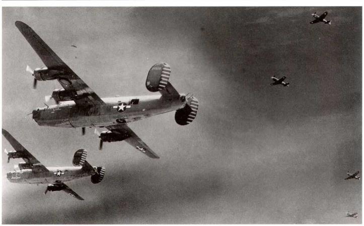
Consolidated B-24D-165-CO, 42-72869, of the 93rd BG, 2nd BW, Eighth Air Force, in late 1943, with the red outline insignia grayed over. (USAF)

image244

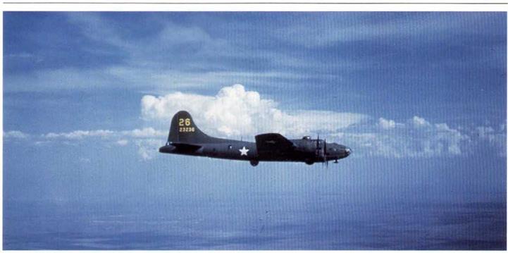
Boeing B-17F-40-DL, 42-3236, aircraft number 26 of a training unit in early 1943. (USAF via Gerry R. Markgraf)

Camouflage Paint on USAAF Airplanes in the United Kingdom, January 2,1944

Gen. Eaker sent a letter to the CGs,, Ninth Air Force, VIII Bomber Command and VIII Fighter Command, on January 2,1944. This stated that in the near future, certain types of aircraft arriving in the theater would be uncamouflaged. The Generals were directed to notify the VIII Air Force Service Command as to their intentions regarding the use of uncamouflaged combat aircraft, at the earliest possible date. The final decision in this regard was to remain in the hands of the responsible Tactical Commander.

The policy in the theater concerning use of uncamouflaged aircraft would be established through the decisions reached as above. This letter gave the Tactical Commanders concerned the authority to operate their combat aircraft without camouflage if so desired.

On January 15, 1944, Ninth Air Force HQ. replied to F. aker’s letter, stating that their policy would be as follows:

a. Fighter Aircraft. All operational fighters used by IX Fighter Command would be camouflaged, and any uncamouflaged aircraft received would be camouflaged. This would cause extra work for the depot and service units and they would prefer to receive all fighters destined for IX AF in camouflage. They also would, if possible, polish the camouflage paint to attain the equivalent of an RAF “fighter finish”, as this would give them the same performance as uncamouflaged aircraft.

b. Bomber Aircraft. The IX Bomber Comand would use either camouflaged or uncamouflaged aircraft, in an “as received” state. Aircraft delivered uncamouflaged would not be painted, nor would paint be removed from those already camouflaged. No change in operational tactics was anticipated for uncamouflaged aircraft.

c. Troop Carrier Aircraft. The IX Troop Carrier Command did not want to use uncamouflaged aircraft, and any uncamouflaged aircraft delivered to them would be camouflaged before delivery to combat units.

image273

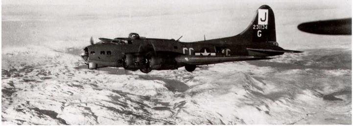
Boeing B-17G-5-BO, 42-31134, aircraft CC-G of the 569th BS, 390th BG, taking part in the major offensive against the German aircraft industry in February 1944. Note the while rectangle with the black letter “J” within it; it has usually been called a “square”, but the orders clearly defined a rectangle. It could be seen in a horizontal position on aircraft with wide code letters (see chapter 6 for more information). (USAF)

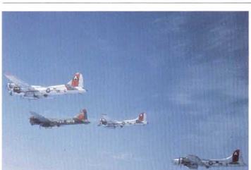
Four Boeing B-17Gs of the 323rd BS, 91st BG, 1st CBW, 1st Air Div, Eighth Air Force, over clouds with bomb doors open. Lead aircraft is in Dark Olive Drab and Neutral Gray, with yellow code letters OK-K, others all in natural metal, code letters OK-C, S, and K. Note how the red tail markings show up the different color triangles on the Olive Drab and natural metal aircraft. (ESAF)

image274image275"Material Command issues Military Requirements Policy No. 60, concerning AAF insignia on leased commercial aircraft, Janu­ary 6, 1944.

To clarify any misunderstanding concerning the camouflage of AAF aircraft, Material Command issued Military Requirements Policy No. 60 on January 6, 1944. This stated that Army camouflage, insignia and markings were not to be used on any commercial aircraft leased to the AAF, but not flown by AAF crews. Such camouflage, etc., was to be used on any commercial aircraft leased to the AAF for a continuous period exceeding ninety days, which was flown and maintained by AAF personnel. Any AAF aircraft loaned to any other government agency and not flown by AAF crews were to have all Army camouflage, insignia and markings removed before delivery.

Preparation for Stripping

If possible, stripping should be done in the open air but not in direct sunlight. To be satisfactory, inside locations must be well ventilated. Personnel should be kept out of the airplane during stripping and the subsequent clean-up procedure. Aircraft should not be stripped on asphalt floors or runways as the paint remover will attack asphaltic base materials.

In order to allow workmen to apply the remover over large areas, arrange ladders and platforms to permit easy access to the surfaces which are to be stripped. Rubber-surfaced equipment should not be used because contact with the paint remover will make it very slippery.

Mask off or remove all exposed parts consisting wholly or partly of plastic, rubber, fabric or other поп-metallic materials, and all painted areas not to be stripped. For masking, use waterproof cloth or a double thickness of Kraft 40-pound paper and masking tape. Because the parts to be removed or masked off differ from one model to another, the following list will serve only as a general guide.

1. De-icer boots and attaching fairing strips. Overlap the camouflage finish approximately 11/2 inches from the trailing edge of the fairing strip.

2. Windows, windshields, navigator’s dome, and the weather sealing used around these parts.

3. Fabric-covered control surfaces: These surfaces should be removed unless they can be masked off completely and adequately. If removed, place them a safe distance from the airplane to avoid possible splashing or excessive exposure to fumes from the remover.

4. Landing gear and tires: In addition to masking off the landing gear and tires, the airplane must be jacked tip and placed on blocks at least one inch thick to avoid possible contact with the remover.

5. Air scoop, oil cooler, and other openings and vents: Mask off all openings through which the remover can gain access to the interior surfaces of the airplane.

6. Demountable power plant assemblies: The antidrag rings and cowl flaps should be removed and the complete power plant assembly covered with waterproof cloth.

7. Propellers, hubs, and domes.

8. All open seams, such as those around the pilot’s door, escape hatches, cargo compartment doors, and fuel tank access doors.

image356

Consolidated B-24J-35-CO, 42-73318 and B-24J-25-CO, 42-73253, of the 425“’ BS, 308,h BG, on their way to bomb targets in Sinshih, China. Standard camouflage, with yellow stripes on the O. D. rudders. They are being escorted by Curtiss P-40s of the Nth Air Force, China. (USAF)

9. All weather-sealed joints between the nose section and the fuselage, between various sections of the fuselage, and between the fuselage and the tail cone.

10. Ail miscellaneous rubber, neoprene, Plexiglas, and other non metallic parts, and all painted areas not to be stripped which may be contacted by the paint remover.

WAR-WEARY AND SURPLUS AIRCRAFT

Two-inch letters will be stenciled directly beneath the type, model, and series designation on the fuselage of aircraft (with insignia red paint materials) in the following categories. This stenciling will be applied by activities at which the affected aircraft are now stationed, and will also include affected aircraft received in the future without these markings:

a. The letter “W” will be stenciled on ail war-weary aircraft which have not undergone a complete DIR. The term “WAR-WEARY” applies to any aircraft returned permanently from service in an overseas theater.

image425

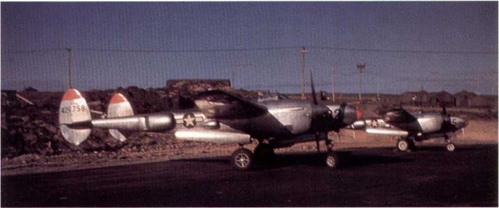
Another view of the 343rd FG P-38L-5-LO, al Shemya in September, 1945. (USAF via Gerry R. Markgraf)

b, The letter “Q” will be stenciled on all war-weary aircraft that are processed through a depot for DIR. This symbol will replace the “W,” which will no longer appear on the aircraft.

c. The tetter “S” will be stenciled on all aircraft which have been declared by Headquarters, Army Air Forces, excess to the military requirement or surplus to the War Department or both. (Reference paragraph 9.a., AAF Regulation 65-86.) Under no circumstances will the letters “S" be used to indicate, or be interpreted to mean, “storage.” In cases where the symbol “W” or “0” is required to be placed on the aircraft, the “S” will be stenciled directly after that symbol. Example: “WS” – “QS.”

Propeller Blades and Hubs to be black, May 1941

Steady progress in the development of new camouflage finishes and requirements inevitably led to continued amendments to Spec. 24114. Unfortunately, Amendment No. 2 has been lost (therefore there is no exact record as to what was said in it). Amendment No. 3 dated May 9, 194І, specified that all propeller blades and hubs should be painted matt black on all surfaces. Paragraph E-5 required that:

All external surfaces of airplane propellers and hubs, after the provisions of Paragraph E-la have been complied with, will be sprayed with one coat of zinc chromate primer, Specification No. 14080. The final finish shall consist of one light coat of cellulose nitrate camouflage lacquer, Specification No. 14105. The color of all external surfaces shall be black in accordance with 14080. The final finish shall consist of one light coat cellulose nitrate camouflage lacquer. Specification No. 14105. The color of all external surfaces shall be black in accordance with Shade No. 44, Bulletin No. 41. After the propeller and hub have been camouflaged and prior to installation, the propeller assembly will be checked for balance.

This was to be the last amendment to Spec. 24114 issued by the Air Corps, later ones being issued by the Army Air Forces.

image43

image44

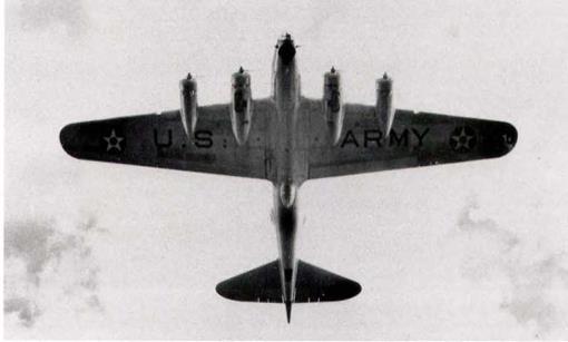
Boeing B-17B of the 19th BG, March Field, shows the standard “U. S. ARMY” marking under the wing. The two underwing cocardes were replaced by a single one under the right wing in Spec. 24114. (March AFB Museum)

image45

image46

Boeing B-17E-BOs, 41-9141 and 41-9131, flying near Seattle are in two different finishes. The nearest one has been repossessed from an RAF batch and is painted in dark green and dark earth over deep sky, with an RAF fin flash, while the other one is in dark olive drab and neutral gray. 512 of this version were built and were considered to he the first real combat-ready B-17. (USAF)

Colors for TVaining Airplanes (Specification 98-24113)

Colors for Advanced, Primary, and Basic trainers were called out in Spec. No. 98-24113-А, dated September 9,1938, and the appli­cable portions follow (with the colors corrected to the new Army-Navy Porcelain Color Plates of September 1,1938):

image47

Spec. 98-2411Э-А, Color for Army Air Corps airplanes

Exterior (Exposed) Surfaces.

Primary and Basic Training Airplanes

Advanced Trainers

Ailerons-both surfaces

Orange Yellow

Aluminum (1)

Cowling

True Blue

Aluminum (1)

Elevator-botb surfaces

Orange Yellow

Aluminum (1)

Fins-bolh surfaces

Orange Yellow

Aluminum (1)

Flaps-both surfaces

Orange Yellow

Aluminum (1)

Fuselage

True Blue

Aluminum (1)

Fairing, fuselage-wing

True Blue

Aluminum (1)

Horns, fittings, etc.

Color of surface to which attached

Aluminum (1)

Rudder, balanced section

Orange Yellow

Aluminum (1)

Rudder, aft of rudder post

Standard rudder insignia

Standard rudder insignia

Skis

No added finish

No added finish

Spinners

True Blue

Aluminum fl)

Stabilizers-both surfaces

Orange Yellow

Aluminum (1)

Struts-landing gear

True Blue

Aluminum Ш

Struts-wing

True Blue

Aluminum (1)

Struts-wire braces

True Blue

Aluminum (1)

Struls-fairing

True Blue

Aluminum (1)

Step-plates

Black

Aluminum (1)

Tail Wheel Fork

True Blue

Aluminum (1)

Walkways

Black

Black

Wings-both surfaces

Orange Yellow

Aluminum (1)

Wheel Cowling

Aluminum

Aluminum (1)

Highly Reflecting Surfaces i. e. The fuselage decks forward of the pilot’s compartment and the inboard side of engine nacelles.

Flat Bronze Green (3)

Flat Bronze Green (3)

Interior (Enclosed) Surfaces

Primary and Basic Training Airplanes

Advanced trainers

Wings and Control Surfaces, including ribs, spars, and all interior structures

Optional

Optional

Fuselages, excepting compartments for personnel, luggage, and cargo

Optional

Optional

Cockpits for pilots and observers which are open or for which sliding enclosures are provided
Yellow Green (2)

Yellow Green (2)

Closed cockpits, the top and sides of which form part of the fuselage structure

Floor and sides to tops of windows: Flat Bronze Green No. 9 (3). Sides above windows and ceilings: aluminum

Floor and sides to tops of windows: Flat Bronze Green No. 9 (3). Sides above windows and ceilings: aluminum

Seats and upholstering for seats, carpets, drapes, etc.

Flat Bronze Green No. 9 (3).

Flat Bronze Green No. 9 (3),

Luggage, cargo and bomber’s compartment

Yellow Green (2)

Yellow Green (2)

NOTES:

(1) Parts and surfaces fabricated from the following aluminum alloys and corrosion resistant steels are used in the natural metal finish without paint coatings, except anti-glare coating:

Aluminum covered Aluminum Alloy, Specification No. 11067.

Aluminum Alloy, Specification No. 11072.

Aluminum Alloy, Specification No. QQ-A-359.

Aluminum, Specification No. 57-151-1.

Corrosion Resistant Steel, Specification No, 11068.

Parts and surfaces manufactured from other metals or fabric shall be finished with aluminum, enamel, lacquer or dope as specified.

(2) Yellow Green is prepared by mixing:

Zinc Chromate Primer, Specification No, 14080 -1 gallon.

Black Enamel, Specification No. 3-98 – 1/10 gallon.

Aluminum Powder, Type B, Specification No. TT-A-476 – 4 ounces,

Toluene, Specification No. 50-11-38 -1 gallon.

(3) Flat Bronze Green is to match color chip No. 9, Color Card Supplement Specification No. 3-1. The lacquer or enamel shall produce a matt appearance of minimum gloss.

image48

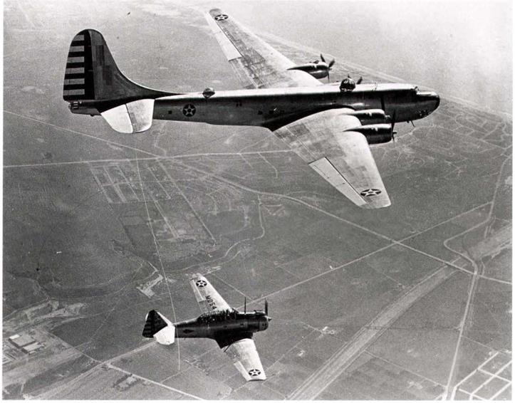
Douglas XB-19, 38-471, in flight over Santa Monica with an AT-6. It first flew on June 27, 1941, in natural metal finish, and was the largesi aircraft to enter AAF service until the B-36. (Nick Williams)

These requirements covered primary and basic training airplanes finished in the true blue and orange yellow color scheme, together with advanced trainers finished in aluminum or natural metal finishes. This spec, also covered the interior yellow-green color; this was not matched to any specific color chip, but was prepared by mixing zinc chromate primer, black enamel and aluminum powder, as specified.

Thus, just prior to entry into World War II, the Army Air Forces had no less than three standard trainer aircraft finishes; (1) the orange yellow and true blue scheme; (2) aluminum paint finish; and (3) natural metal finish.